Data Sciences TRUDSI Animal implant for medically related applications in laboratory environments User Manual Doc To Help Standard
Data Sciences International Inc Animal implant for medically related applications in laboratory environments Doc To Help Standard
Contents
- 1. System Users Manual
- 2. Original Replacement file was incorrect (replaces last page, MHATRXDSI NOT)
- 3. Surgical implantation procedures
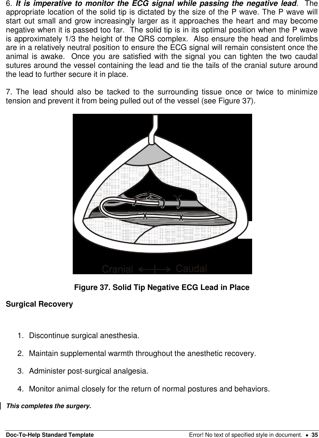
Surgical implantation procedures
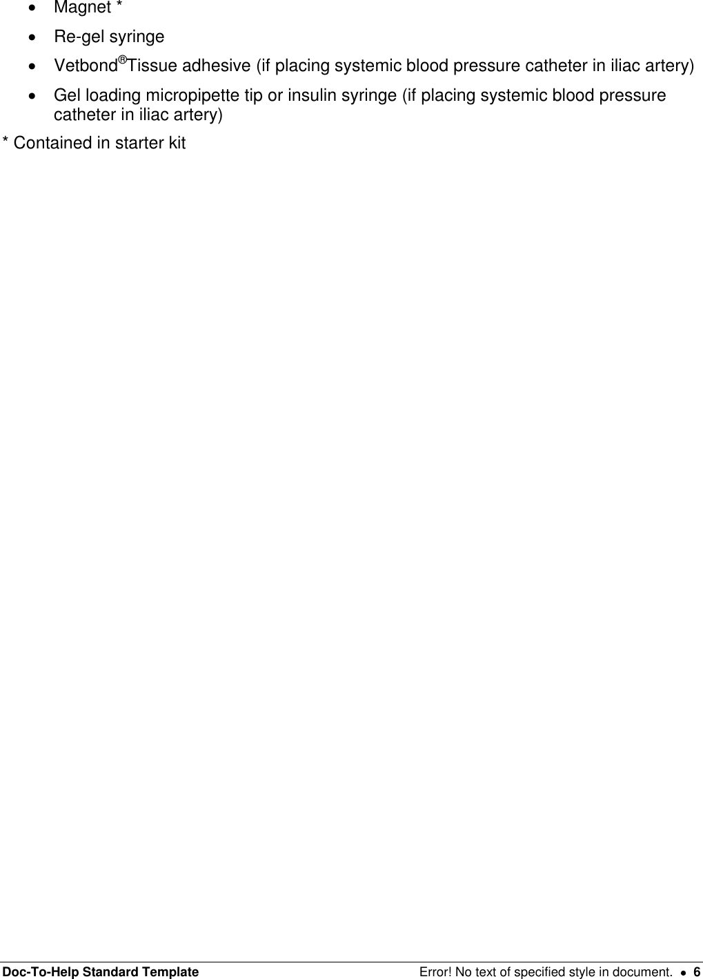
![Doc-To-Help Standard Template Error! No text of specified style in document. 5 Required Supplies for the PhysioTel®Digital Surgery EQUIPMENT Clippers Supplemental heating PhysioTel®Digital device Ponemah 5.1 data collection system Mechanical ventilator INSTRUMENTS Details contained in Appendix D SUPPLIES Surgical scrub (Chlorhexidine or Providine-Iodine scrub) Sterile drapes Sterile gloves, hair bonnet and face mask Sterile surgical gown Sterile gauze sponges-4 inches x 4 inches (10 cm x 10 cm) Sterile saline Sterile basin 2% Lidocaine Elastic vessel loops 2-0 * to 4-0 (Smaller or larger suture may be needed depending on size and species used) non-absorbable, non swaged suture[MES1] 2-0 to 4-0 (Smaller or larger suture may be needed depending on size and species used) non-absorbable suture swaged on a tapered needle[MES2] 2-0 or 4-0 (Smaller suture may be needed depending on size and species used) absorbable suture material swaged on a tapered needle[MES3] 2-0 to 4-0 (Smaller suture may be needed depending on size and species used) absorbable surgical suture swaged on a cutting needle[MES4] 14-gauge hypodermic needle * 20-gauge hypodermic needle * Catheter introducer (i.e. vein pick)*](https://usermanual.wiki/Data-Sciences/TRUDSI.Surgical-implantation-procedures/User-Guide-1717985-Page-5.png)
![Doc-To-Help Standard Template Error! No text of specified style in document. 7 Anesthesia and Analgesia Guidelines Proper peri-operative pain control and anesthesia are critical to humane treatment of laboratory animals. Each institution’s staff veterinarian should be contacted for proper analgesic and anesthetic protocols and training before survival surgery is attempted. The use of pre- and post-surgical analgesics is strongly encouraged for all surgical manipulations performed on laboratory animals. “The proper use of anesthetics and analgesics in research animals is an ethical imperative…The selection of the most appropriate analgesic or anesthetic should reflect professional judgment as to which best meets clinical and humane requirements without compromising the scientific aspects of the research protocol.”1 Questions regarding the use of analgesics should be directed to your staff veterinarian. Typically, the surgical procedure for the TS-L11 will require 60 minutes of surgical anesthesia, and the surgical procedure for the TS-L21 device will require approximately 120 minutes of surgical anesthesia. Intermittent positive pressure mechanical ventilation is required any time the thoracic cavity is opened, such as during placement of a left ventricular pressure catheter. Appropriate use of this technique is essential, and should be directed by the staff veterinarian. The surgical procedures described in this manual were developed using inhalational anesthesia consisting of Isoflurane delivered in 100% Oxygen. These recommendations are intended as a guide only and should be modified to the individual animal and institution’s protocol. Anesthetized animals are predisposed to hypothermia. The use of supplemental heat sources such as warm water re-circulating heating pads or Bair Huggers® are important to maintain baseline body temperature. Hypothermia will prolong the recovery period and may result in animal loss. For additional help in determining an appropriate anesthetic protocol, the staff veterinarian should be contacted. DSI has also prepared an Anesthesia Reference Manual as a guide to assist in choosing an appropriate anesthetic agent for a wide variety of common laboratory species. 1 Guide for the Care and Use of Laboratory Animals, NRC, National Academy Press, 1996 [MES5]](https://usermanual.wiki/Data-Sciences/TRUDSI.Surgical-implantation-procedures/User-Guide-1717985-Page-7.png)
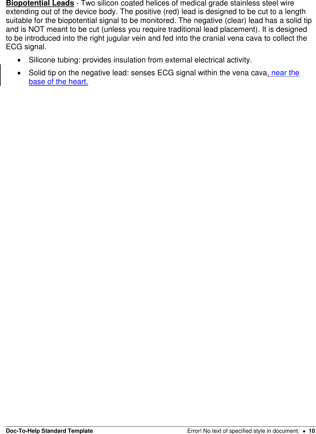
![Doc-To-Help Standard Template Error! No text of specified style in document. 8 Peri-operative Antibiotics and Antiarrhythmic Medications The use of antibiotics may be elected at the discretion of the investigator. The combination of sterile device packaging and proper aseptic technique help increase the potential for successful surgical outcomes. Investigators should follow the guidelines of their own institution. Questions regarding the use of antibiotics should be directed to the institution’s staff veterinarian. Due to the manipulation of the heart, there is a potential to induce an arrhythmia, and the anesthetist may wish to be prepared to deliver antiarrhythmic agents as appropriate. The choice and dose of agents should be determined through consultation with the institution’s veterinarian. Device Description It is important that you are familiar with the device and its function before you attempt implantation (see Figure 1). Figure 1. PhysioTel®Digital Device[MES6] The PhysioTel®Digital device measures pressure, a biopotential signal, temperature, and physical activity in primates, dogs and swine and is a rectangular shaped device. The devices consist of the following major components: Device Body - The titanium housing containing: Pressure sensor: receives pressure fluctuations from the fluid-filled catheter and sends the signals to the electronics module. Reusable electronics module: translates the pressure fluctuations, biopotential signal and temperature into digitized signals and transmits them to a receiver. It also interprets signals received from the laboratory software and contains a magnetically activated switch that allows the device to be switched on or off. Battery: provides the power supply for the electronics module. Suture aid: allows the surgeon to suture the device securely in place at the implant site. Pressure Catheter(s) - Polyurethane tubing that extends (25, 35 or 40 cm) out of the device body and contains: Non-compressible fluid: relays pressure fluctuations to the sensor in the device body.](https://usermanual.wiki/Data-Sciences/TRUDSI.Surgical-implantation-procedures/User-Guide-1717985-Page-8.png)
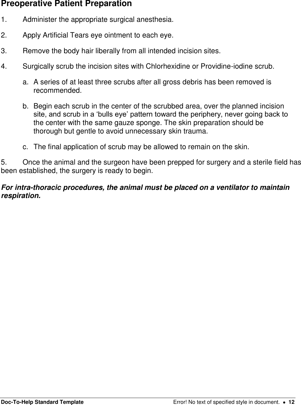
![Doc-To-Help Standard Template Error! No text of specified style in document. 9 Thin-walled section: tip of the catheter farthest from the device body that senses the dynamic portion of the pressure wave. It is designed to be completely inserted into the vessel or space where the desired pressure can be sensed. It contains biocompatible gel at the very tip, which prevents the non-compressible fluid from leaving the catheter and blood from clotting in the catheter tip (see Figure2). Tip cover: removable section of silicone tubing that protects the catheter tip until it is actually inserted into the desired vessel. Must be removed prior to catheter insertion. Systemic blood pressure catheter: containing a radio-opaque ring encircling the distal end of the systemic blood pressure catheter (This is the channel 2 catheter on the TS-L21 PhysioTel®Digital Device.) Left ventricular pressure catheter: containing a plastic suture collar near the tip, with only the thin-walled section protruding beyond. The white suture collar will be inserted until the suture groove is flush with the heart wall (see Figure 3). It is important to be familiar with the catheter and its features. See the figure below for a detailed diagram of each catheter. Figure 2. The PhysioTel®Digital catheter Figure 3. The Left Ventricular Catheter Tip With Collar[MES7]](https://usermanual.wiki/Data-Sciences/TRUDSI.Surgical-implantation-procedures/User-Guide-1717985-Page-9.png)
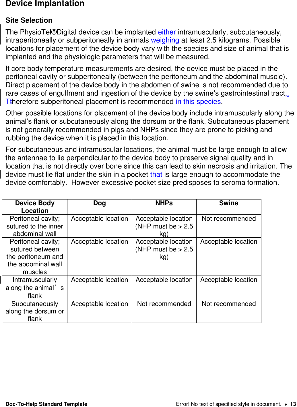
![Doc-To-Help Standard Template Error! No text of specified style in document. 11 Figure 4. [MES8]Solid Tip Biopotential Lead Device Handling ALWAYS handle the device with care supporting both the device body and catheters from underneath when moving or placing the device. Allowing the catheters to hit a solid surface can damage the pressure sensor. Before removing the device from its sterile package Turn the device to the ON mode with a magnet and audibly verify proper device operation with a DSI receiver. 1. Record the serial number of the device and ensure that the device has been identified with the animal into which it will be implanted. 2. Measure and record the pressure offset. Refer to Appendix E for further information on this process. To Hydrate the Catheter 1. Open the sterile package by peeling back the white package cover from the clear plastic tray. Do not discard the white package cover as it contains important device calibration information. Also doDo not discard the sterile package as it can be used for eventual return of the device to DSI. 2. Place the device and catheter into a sterile basin with sterile saline warmed to body temperature. Do not heat the sterile saline higher than body temperature as this can result in clotting at the catheter tip once it is placed in the animal. 3. The catheter should be hydrated for approximately 30 minutes before implantation. Note: The catheter is very hydrophilic and, if not hydrated, will absorb water from the blood. This can cause the gel to recede due to catheter expansion and leave a void at the tip of the catheter, which could increase the risk of blood clot formation. WARNING: Do NOT use surgical electrocautery on the animal once the device is on the surgical tableimplanted into the animal. Use of electrocautery once the ECG leads are implanted will cause failure of the device!](https://usermanual.wiki/Data-Sciences/TRUDSI.Surgical-implantation-procedures/User-Guide-1717985-Page-11.png)
![Doc-To-Help Standard Template Error! No text of specified style in document. 14 Intra-abdominal Placement: Intraperitoneal/Subperitoneal Intraperitoneal/subperitoneal placement is appropriate for canines and non-human primates weighing ≥ 2.5 kg. Due to potential device engulfment by the intestines, intraperitoneal placement is not recommended in swine; instead a modified subperitoneal approach is favored. The intraperitoneal/subperitoneal placement is particularly useful when the trans-diaphragmatic approach is used to access the heart for left ventricular pressure catheter placement, since access to the peritoneal cavity will have already been established. 1. Make an incision through the skin and subcutaneous tissues between the xyphoid process cranially and the umbilicus caudally (length will vary according to procedure, and can be extended as needed). 2. Make a small incision in the body wall through the linea alba (tenting can prevent trauma to underlying viscera), then insert a forceps or grooved director and use a scalpel with the sharp edge facing externally to extend the incision. Keep The length of the incision in the body wall should be lesssmaller than the skin incision to allow for closure (see figure 4). Figure 5. Midline Abdominal Incision[MES9] Subperitoneal placement Intraperitoneal placement 3a. Make an incision into the peritoneal lining of the abdominal wall approximately 2-3 cm to the left animal’s left of the midline incision (the surgeon’s right) large enough to place the device portion of the device. 3b. Gently retract the left side of the abdominal wall slightly to expose the internal surface approximately 2-3 cm away from the incision. 4a. Use a mayo scissors to create an appropriately sized pocket using blunt dissection. Place the device inside the pocket with the catheters and biopotential leads oriented cranially and the antennae perpendicular to the device body, towards the opposite side of the abdomen. (i.e. with 4b. Place the device inside the abdomen to animal’s left of the midline incision (the surgeon’s right). Orientate the catheters and biopotential leads cranially and the antennae perpendicular to the device body, towards the opposite side of the abdomen. (i.e. with device is placed on the left side of the linea](https://usermanual.wiki/Data-Sciences/TRUDSI.Surgical-implantation-procedures/User-Guide-1717985-Page-14.png)
![Doc-To-Help Standard Template Error! No text of specified style in document. 15 the device is placed on the left side of the linea alba the antennae will run along the abdominal wall, across the abdominal incision, towards the right side of the abdomen.) alba the antennae will run along the abdominal wall, across the abdominal incision, towards the right side of the abdomen.) 5a. Secure the device body to the inside of the abdominal wall by suturing the suture aids to the inner abdominal muscle using non-absorbable suture, it may not be possible to place a suture through the deepest suture tab. 5b. Secure the device body to the inside of the abdominal wall by suturing the suture aids to the inner abdominal muscle using non-absorbable suture. Be sure the device body is secured away from the incision site so that it will not interfere with healing once the incision is closed. 6a. Close the subperitoneal pocket using absorbable suture material in a simple continuous pattern. 6b. N/A 7. Do NOT secure the antennae; the antennae will be secured just prior to closing the abdomen (see below). 8. The negative (± positive) biopotential lead(s) will now need to be exteriorized from the peritoneal cavity by passing a 14 gauge needle from outside of the abdomen to inside, next to the incision. The lead can then be passed into the needle which is then withdrawn. Figure 6. Cather and Biopotential Lead Exteriorization[MES10] 9. As soon as access to the abdominal cavity is no longer needed (after catheter(s) and biopotential leads have all been exteriorized/placed) the abdominal incision should be closed. 10. Before closing the abdominal wall, the antenna of the device must be secured. A small incision (~1cm) should be made in the peritoneum just next to the right of the midline incision (surgeon’s left), across from the body of the device.](https://usermanual.wiki/Data-Sciences/TRUDSI.Surgical-implantation-procedures/User-Guide-1717985-Page-15.png)
![Doc-To-Help Standard Template Error! No text of specified style in document. 16 Figure 7. PhysioTel®Digital Device Placed Intraperitoneally[MES11] 11. Next a small pocket should be tunneled in the subperitioneal space using blunt dissection with a mayo scissors or a straight hemostat to provide a secure location for the antenna to sit. 12. The body wall can be temporarily apposed near the antenna (without including the antenna itself) using an interrupted suture or a towel clamp. 13. The body wall should be closed in 2-3 layers. The first layer is the muscular body wall itself which should be closed in a simple interrupted pattern with an monofilament absorbable suture of the appropriate size. 14. Next, the subcutaneous tissue should be closed in a simple continuous pattern using an absorbable material, burying the knots. 15. Finally, skin should be closed in an intradermal/subcuticular pattern using an absorbable suture material. This pattern is recommended to prevent post-operative irritation. Tissue glue may be used to seal the incision if the surgeon chooses. Extraperitoneal Placement: Intramuscular/Subcutaneous Intramuscular or subcutaneous device placement is appropriate in laboratory animals where the anatomy allows for a sufficiently sized pocket in the flank (paralumbar fossa area) in which the device and antenna can lie flat and at 90 degrees to one another. The device and antenna must also lie in a location that does not place either portion of the device over bone. No implants should be placed directly underneath an incision, as this can interfere with proper healing, but rather the overlying tissue should be undermined to create a pocket that lies slightly distant from the incision. The intramuscular placement provides additional soft tissue between the device body and the skin and has been noted to reduce the incidence of rubbing or scratching in swine and non-human primates. Figure 8. PhysioTel®Digital Device in SQ/IM Pocket with Antenna at 90 Degrees Lateral Recumbency 1. Place a straight to curvilinear incision, slightly longer than the device body, in the paralumbar fossa area, between the tuber ischii and the last rib. A second smaller stab skin incision should be made at the point to which the antenna is expected to extend (as determined by estimating approximate device location prior to surgery) at a 90 degree angle to the device body. Figure 9. Subcutaneous/Intramuscular Placement in Lateral Recumbency Figure 10. Abdominal Wall Muscle Layers](https://usermanual.wiki/Data-Sciences/TRUDSI.Surgical-implantation-procedures/User-Guide-1717985-Page-16.png)
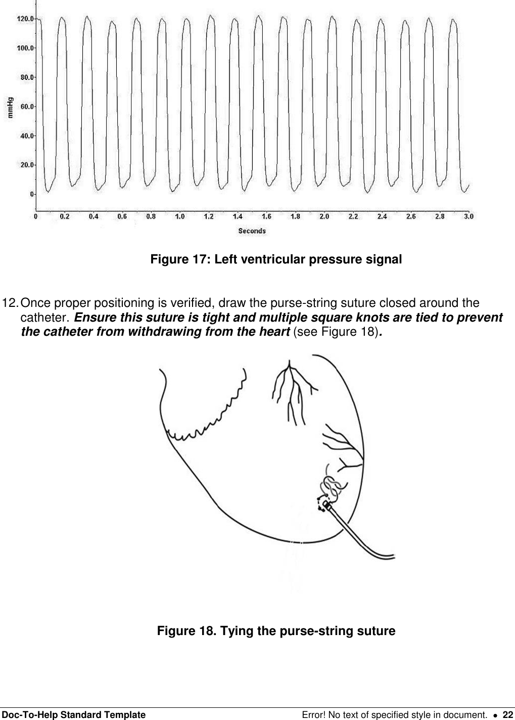
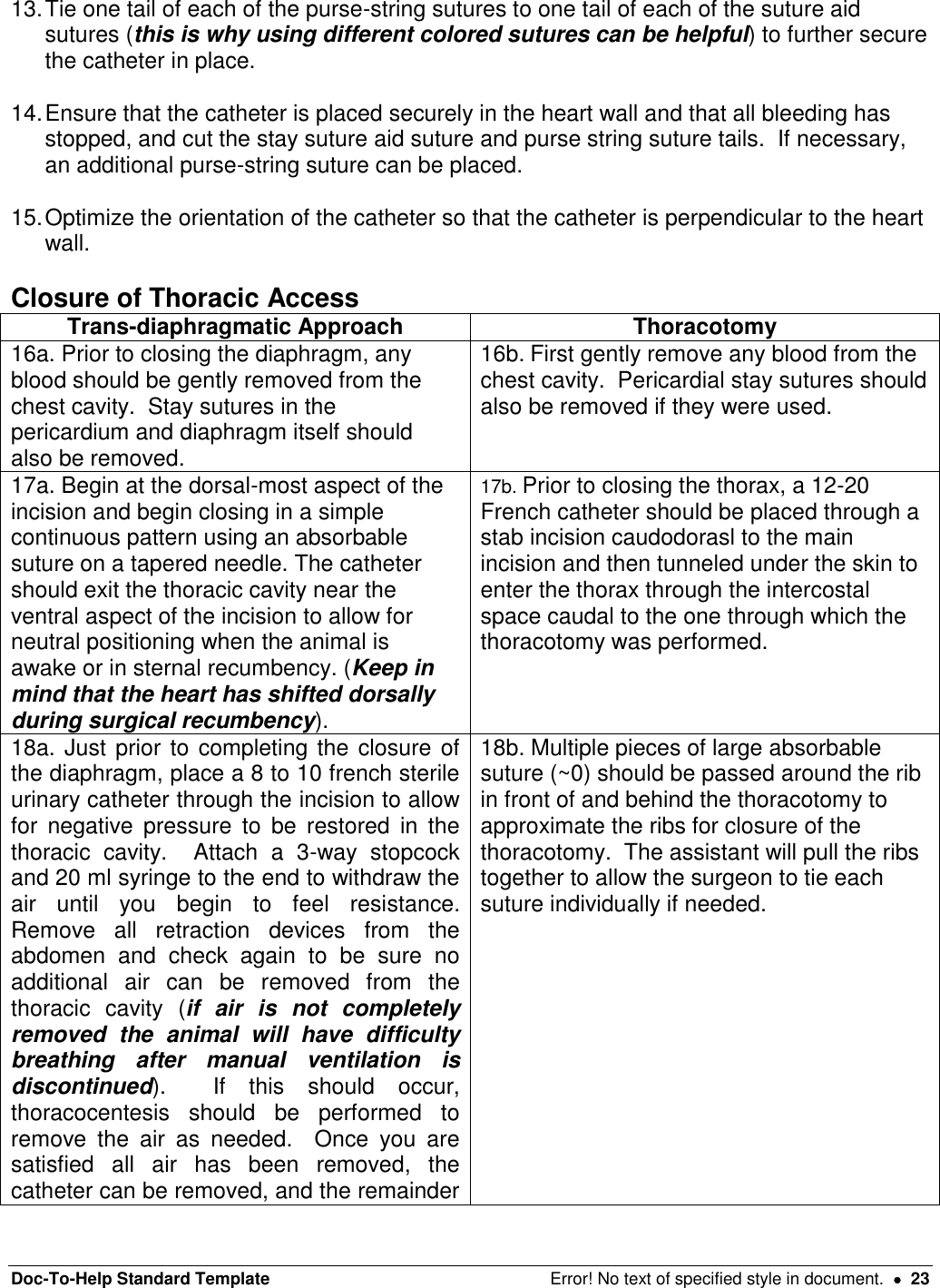
![Doc-To-Help Standard Template Error! No text of specified style in document. 19 of the heart. Remembering that during dorsal recumbency the animal’s heart shifts from its natural position so the incision should be placed slightly ventrally. small nick in the intercostals muscles, being very careful to center the incision midway between the cranial and caudal rib; this prevents trauma to the intercostals nerve and blood vessels running along the caudal aspect of the cranial rib and provides adequate tissue for closure. Then extend the incision using a push-cut method dorsally to the tubercle of the rib and ventrally past the costochondral arch to the internal thoracic vessels (avoid cutting these vessels). 3a. The diaphragm may be kept open by placing stay sutures in the diaphragm on each side of the incision using 3-0 or 4-0 suture with a taper needle. Secure the ends of the stay suture with a hemostatic clamp which can then be held by an assistant. 3b. Place wet laparotomy sponges or gauze squares under the blades of a finochietto retractor which can be used to expose the heart and vessels. *A rib resection may provide additional access to the thoracic cavity, especially in swine, due to the anatomical difference of a wider rib. Figure 12. Trans-diaphragmatic Approach to Left Ventricle[MES12] Figure 13. Thoracotomy Approach to Left Ventricle[MES13] 1. Incise the pericardium to allow for access to the apex of the heart. Begin the incision by tenting the pericardium over the apex and extend the incision cranially, stopping before reaching the phrenic nerve that runs through the pericardium horizontally along the base of the heart. Next, extend the incision to the right and left below the phrenic nerve, exceess pericardial tissue can be excised. 2. Stay sutures using 3-0 or 4-0 suture on a tapered needle may be placed in the pericardium on either side of the incision to improve access to the apex of the heart. Secure the ends of the stay sutures with clamps which can be manipulated by an assistant. Minimize cardiac retraction as it can cause poor flow into and out of the heart, severe hypotension and arrhythmias. Monitor blood pressure and ECG closely when manipulating the heart. 3. Identify the target area at the apex of the heart and install a purse-string suture usinig 3-4 partial-thickness bites (avoid entering the lumen) in the myocardium (see Figure 13). This should be done using 3-0 or 4-0 non-absorbable suture with a taper needle. Figure 13: Placement of the purse-string suture](https://usermanual.wiki/Data-Sciences/TRUDSI.Surgical-implantation-procedures/User-Guide-1717985-Page-19.png)
![Doc-To-Help Standard Template Error! No text of specified style in document. 25 Figure 20. Medial Saphenous Artery Exposure [MES14] Mesenteric Artery Medial Saphenous/Femoral Artery 1a. Locate an intestinal artery running through the mesentery closely associated with the vein and lymphatic vessel. Choose an artery that has nearby collateral blood supply to avoid compromise to the intestine. Using a fine tipped, curved forceps carefully isolate at least 2.5 cm of the artery. 1b. The pulse of the medial saphenous artery can be palpated on the inside of the thigh with the hindlimb extended straight out behind the animal and rotated externally so the inside of the thigh is easily accessable. A skin incision should be made over the palpable pulse, pulling the skin to the side to avoid damaging the underlying vessel. 1c. The femoral artery originates deeper between muscle bellies. To find it, follow the medial saphenous artery proximally and sharply transect the fascia between muscle bellies (avoid cutting or dissecting through the muscle itself). Continue the dissection proximally and deep to the femoral artery. Once the fascia is cut, blunt dissection can be used to isolate the vessel and a Weitlaner retractor can be used to provide better visualization. 2. Once the appropriate vessel is located, apply a few drops of 2% Lidocaine without epinephrine on the artery to prevent vasospasm. 3. Pass three pieces of non-absorbable suture under the isolated section of artery. Tie the distal-most suture to permanently occlude the blood vessel. The two more proximal](https://usermanual.wiki/Data-Sciences/TRUDSI.Surgical-implantation-procedures/User-Guide-1717985-Page-25.png)
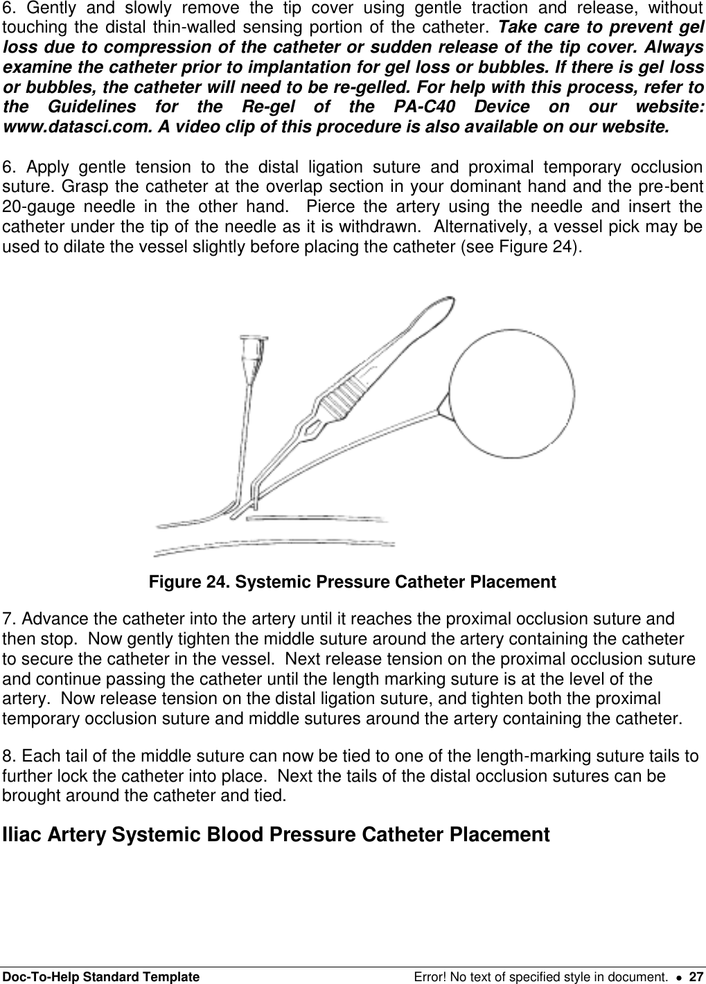
![Doc-To-Help Standard Template Error! No text of specified style in document. 28 1. Carefully locate and isolate the iliac artery. The paired iliac arteries are located in the caudal abdomen and branch directly off of the caudal abdominal aorta and can be palpated by first detecting the aortic pulse and moving caudally (see Figure 25). Figure 25. Iliac Artery 2. Using fine tipped, curved forceps, carefully isolate at least 2.5 cm of the iliac artery from the surrounding tissue and the iliac vein. 3. Pass two elastic vessel loops or two pieces of non-absorbable suture underneath the isolated artery section. Both sutures will be used to temporarily occlude blood flow to allow for placement of the catheter (see Figure 26). Place the loops/sutures as far apart as possible and secure with a hemostatic clamp. Do NOT occlude the vessel until everything is prepared for vessel cannulation. [MES15] Figure 26. Temporary Occlusion of Iliac Artery](https://usermanual.wiki/Data-Sciences/TRUDSI.Surgical-implantation-procedures/User-Guide-1717985-Page-28.png)
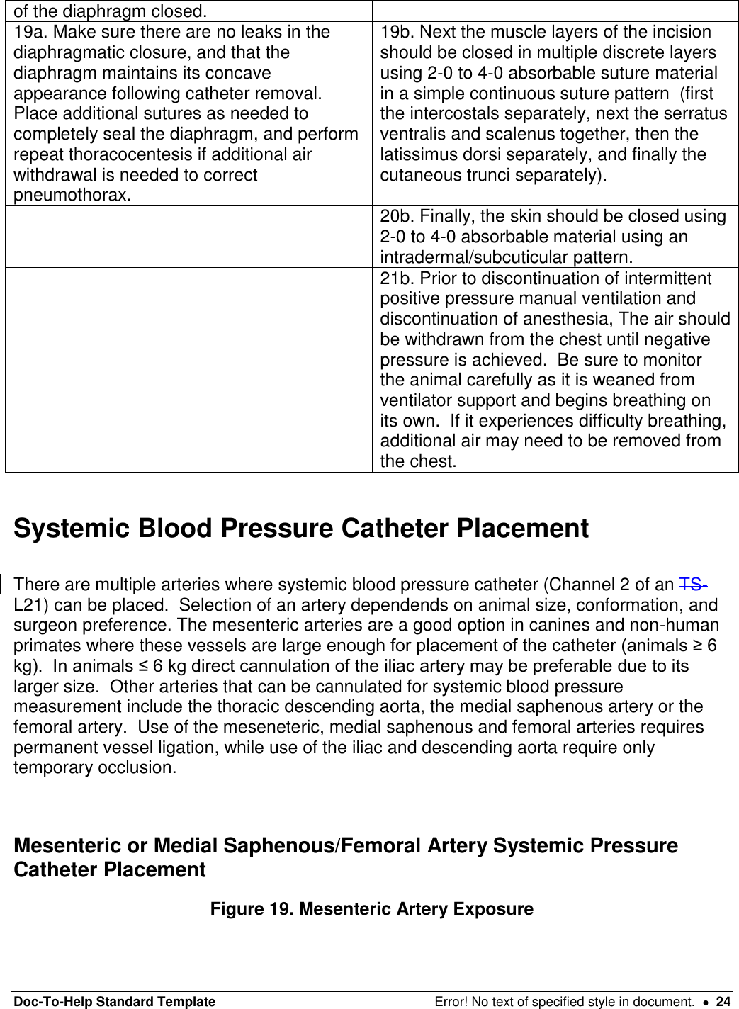
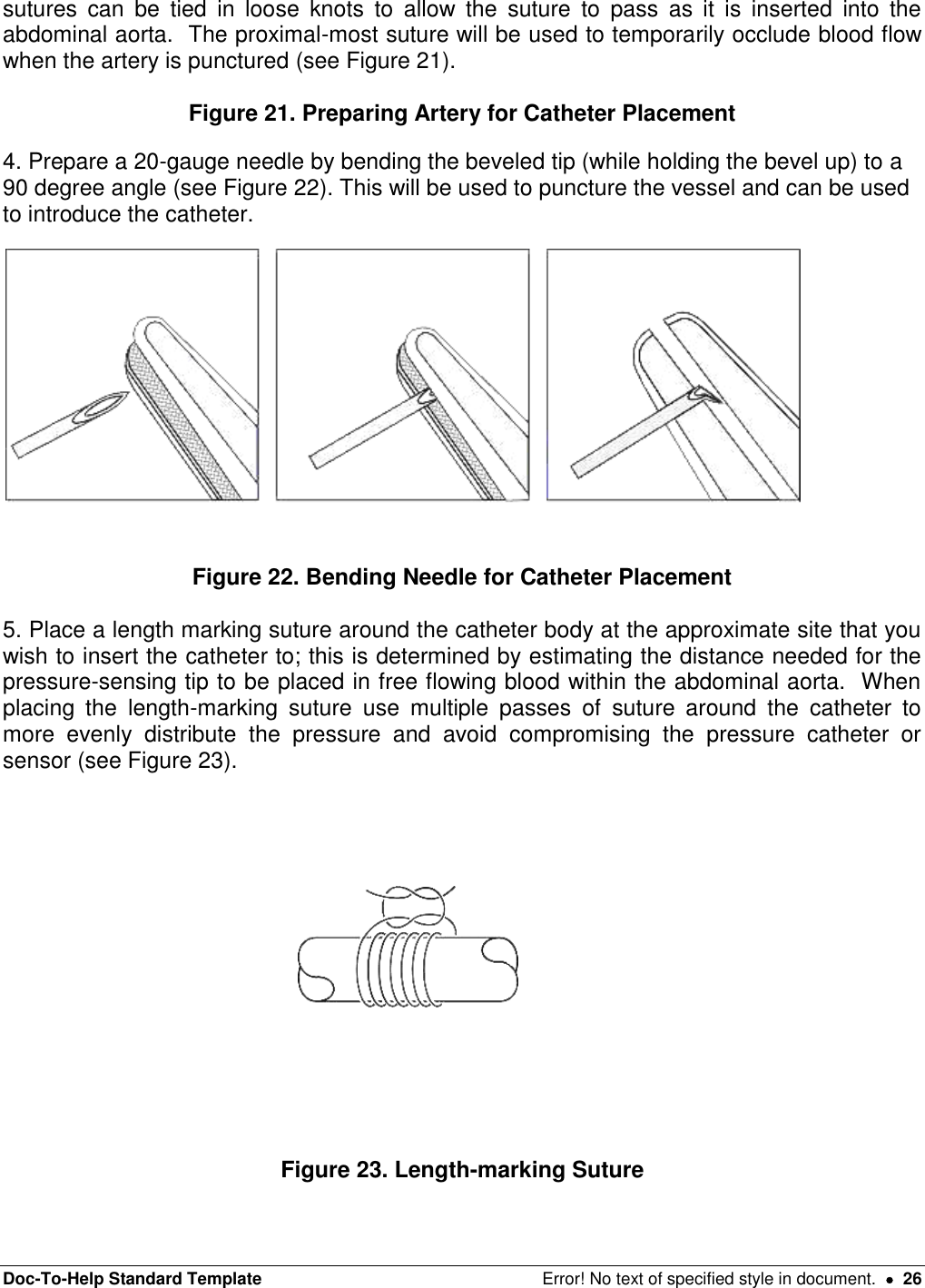
![Doc-To-Help Standard Template Error! No text of specified style in document. 30 11. Secure the catheter that is outside the vessel near the entry site to the lumbar muscles in at least two locations using non-absorbable suture. If the catheter is not secured to nearby muscles there is a high risk that the catheter will back out of the vessel post-operatively, which would result in internal bleeding and loss of the blood pressure signal. Thoracic Aorta Systemic Blood Pressure Catheter Placement 1. The descending thoracic aorta should be identified, and the thin layer of serosal covering carefully dissected away from approximately 1 cm of the vessel’s surface. 2. Next a small purse-string suture should be placed and a knot loosely tied on the surface of the vessel using 3-0 to 5-0 suture material on a tapered needle. Be careful not to take full thickness bites of vessel wall or bleeding will occur. Should this occur apply gentle pressure until bleeding stops. Leave the ends of the purse-string suture long (see Figure 27). Figure 27. Preparation of Thoracic Aorta for Catheterization 3. Complete needle preparation, length marking suture placement and tip cover removal as described above. 4. When you are fully prepared for catheter insertion, apply a Satinsky clamp to the area around the purse string to temporarily occlude blood flow. This clamp should remain in place for the minimum amount of time possible, so be sure everything is fully prepared prior to placement. 5. Once the Statinsky clamp is in place, grasp the catheter at the overlap section in your dominant hand and the pre-bent 20-gauge needle in the other hand. Pierce the artery using the needle and insert the catheter under the tip of the needle as it is withdrawn. Alternatively, a vessel pick may be used to dilate the vessel slightly before placing the catheter. 6. Advance the catheter into the artery, the clamp may have to be temporarily released or adjusted to allow passage of the catheter. Continue advancing the catheter until the length marking suture is at the level of the artery. Now tighten the purse-string suture and ensure no blood leaks around the catheter, if needed, you can place an additional purse string suture around the outside of the first for hemostasis. [MES16] 7. Each tail of the purse string suture can now be tied to one of the length-marking suture tails to further lock the catheter into place and all sutures cut short[MES17](see Figure 28). Figure 28. Purse-string Tightening 8. Secure the catheter that is outside the vessel near the entry site to the lumbar muscles in at least two locations using non-absorbable suture. If the catheter is not secured to](https://usermanual.wiki/Data-Sciences/TRUDSI.Surgical-implantation-procedures/User-Guide-1717985-Page-30.png)
![Doc-To-Help Standard Template Error! No text of specified style in document. 31 nearby muscles there is a high risk that the catheter will back out of the vessel post-operatively, which would result in internal bleeding and loss of the blood pressure signal. Electrocardiogram (ECG) Lead Placement Positive Lead Placement The positive lead must be placed first so you can detect an ECG signal to guide placement of the negative solid tip lead. The positive lead can be placed in a variety of different locations including the abdominal side of the diaphragm, the epicardium, or subcutaneously over the middle of the left ribcage approximately level with the xyphoid process for a lead II ECG or on midline for a base-apex ECG. The choice of location for the positive lead is often dictated by the other surgical approaches being used (i.e. diaphragmatic ECG lead placement with intra-abdominal device placement etc.). Regardless of the site chosen for implantation, the basic technique is the same and will be described below. 1a. If the positive ECG lead will be placed on the diaphragm, it can be placed following closure of the diaphragm following trans-diaphragmatic placement of the left ventricular catheter. It should be placed over the apex of the heart (see Figure 29[MES18]). Figure 29. Diaphragmatic Positive ECG Lead Placement 1b. If the positive ECG lead will be placed subcutaneously there are two different options including a lead II configuration and a base-apex configuration. For the lead II configuration, a small skin incision should be made over the middle of the left ribcage, approximately level with the xyphoid process (see Figure 30). For the base-apex configuration, a small skin incision should be made over the ventral midline at approximately the level of the xyphoid process (see Figure 31). The lead will be exteriorized as needed and passed through a cannula to the site of implantation (as described above in the device body placement description).](https://usermanual.wiki/Data-Sciences/TRUDSI.Surgical-implantation-procedures/User-Guide-1717985-Page-31.png)
![Doc-To-Help Standard Template Error! No text of specified style in document. 32 Figure 30. Lead II ECG Placement Figure 31. Base-apex ECG Lead Placement 1c. If the positive ECG lead will be placed epicardially, it will need to be directed to the thoracic cavity and placed prior to closure of the chest following left ventricular pressure catheter ± thoracic aorta systemic blood pressure catheter placement. 2. Cut the lead to the appropriate length to reach the incision, allowing for growth if needed. Next make a circumferential cut around the silicone covering from the last few centimeters of ECG lead, leaving the exposed wire. Form this wire into a loop with a diameter of approximately 1 cm and secure the loop with a non-absorbable suture. Finally, place another suture a few millimeters from the end of the silicone covering, just before the loop of exposed wire in order to prevent fluid migration (see Figure 32). Cut the tail, but leave the suture attached onto the ECG lead[MES19].](https://usermanual.wiki/Data-Sciences/TRUDSI.Surgical-implantation-procedures/User-Guide-1717985-Page-32.png)
![Doc-To-Help Standard Template Error! No text of specified style in document. 33 Figure 32. ECG Lead Modification 3. Take the suture still attached to the ECG lead and use this to tack the loop to the underlying muscle/tissue. Anchor the exposed portion of the lead to the underlying muscle using at least 3 simple interrupted knots using 2-0 to 0 3-0 non-absorbable suture. You can also tack the lead along its course if you are concerned about tension. Negative Solid Tip Lead Placement The PhysioTel®Digital device will come with a solid tip negative lead. This has been shown to provide accurate ECG signals in animals ≥ 2.5 kg while virtually eliminating muscle noise and artifact. The right external jugular vein has been used in the canine and swine. Due to differing anatomy, the internal juglar vein is recommended in non-human primates. External Jugular Vein Internal Jugular Vein 1a. A skin incision should be made in the jugular furrow to expose the external jugular vein, approximately 4 cm caudal to the confluence of the maxillary and lingofacial veins. The skin can be pulled to the side of the vein so the surgeon isn’t cutting directly over the vessel. The external jugular vein can be used in the canine and swine, but the internal jugular provides a more direct route to the intended location of the solid tip in the cranial vena cava. The external jugular vein tends to be larger and located more superficially (see Figure 33). 1b. The internal jugular vein can be exposed through an incision next to the trachea approximately 1/3 of the distance between the sternum and the corner of the mandible. Blunt dissection should be used and the sternal and clavicular heads of the sternocleidomastoid muscle can be separated to expose the external jugular vein and carotid artery (see Figure 34). [MES20]](https://usermanual.wiki/Data-Sciences/TRUDSI.Surgical-implantation-procedures/User-Guide-1717985-Page-33.png)
![Doc-To-Help Standard Template Error! No text of specified style in document. 34 Figure 33. External Jugular Vein Figure 34. Internal Jugular Vein in Non-human Primate 2. Once the solid-tipped lead is exteriorized at the jugular incision via passing it through a cannula (as described above in device placement description), it’s time to prepare the vessel for cannulation. Pass 3 pieces of non-absorbable suture around the vessel. The cranial-most suture will be used to permanently ligate the vessel. Loose knots can be placed in the other two sutures and the tails left long (see Figure 35). [MES21] Figure 35. Sutures Placed for Solid Tip Negative ECG Lead Placement 3. Tension should then be placed on the caudal suture to temporarily occlude blood flow and on the cranial ligation suture to hold the vessel in place during lead placement. Then pierce the vessel cranial to the middle tie using the bent needle technique (described above). You can then choose to use a vein pick to dilate the opening slightly and gently lift upwards. 5. The solid tipped lead can then be inserted into the vein in a direction toward the heart. Stop passing once the lead is near the caudal occlusion suture. At this point, the middle tie can be gently tightened around the lead to secure it in the vessel and then continue passing the lead into the vein (see Figure 36). Figure 36. Placing Solid Tip Negative ECG Lead](https://usermanual.wiki/Data-Sciences/TRUDSI.Surgical-implantation-procedures/User-Guide-1717985-Page-34.png)