Datalogic S r l 0060 Skorpio X3 User Manual 61590
Datalogic ADC S.r.l. Skorpio X3 61590
UserManual.wiki
>
Datalogic S r l
>
0060 User Manual
>
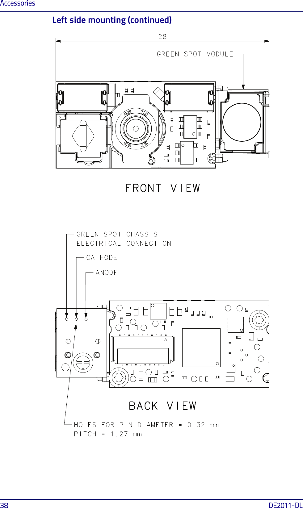
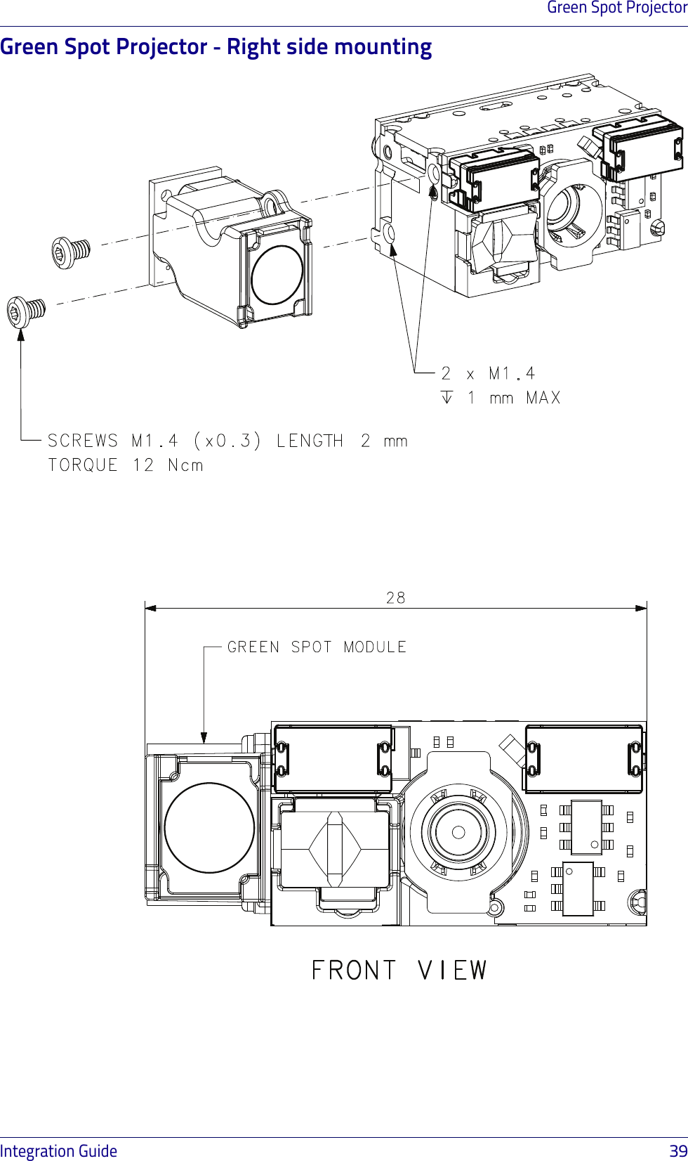
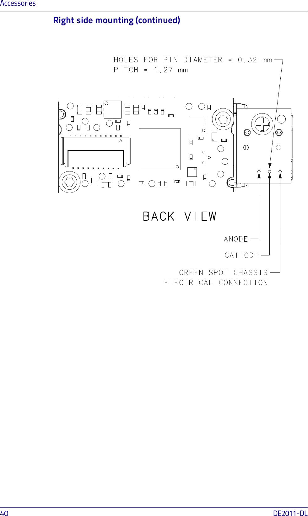
Integration Guide
Contents
1.
user manual
2.
Integration Guide
Integration Guide
Navigation menu
Upload a User Manual
Namespaces
Wiki Guide
HTML
PDF
Info
Views
User Manual
Discussion / Help
Navigation

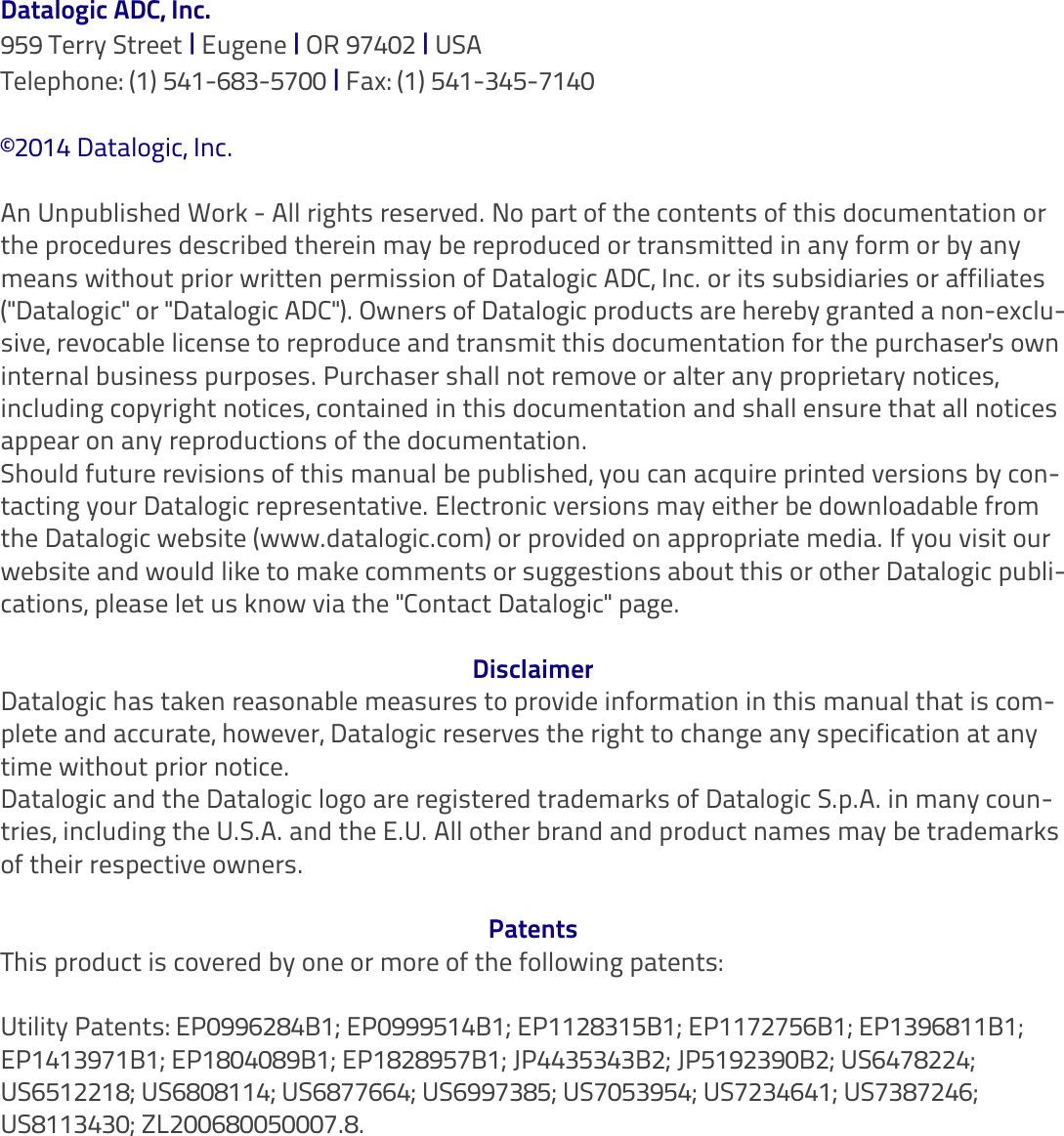
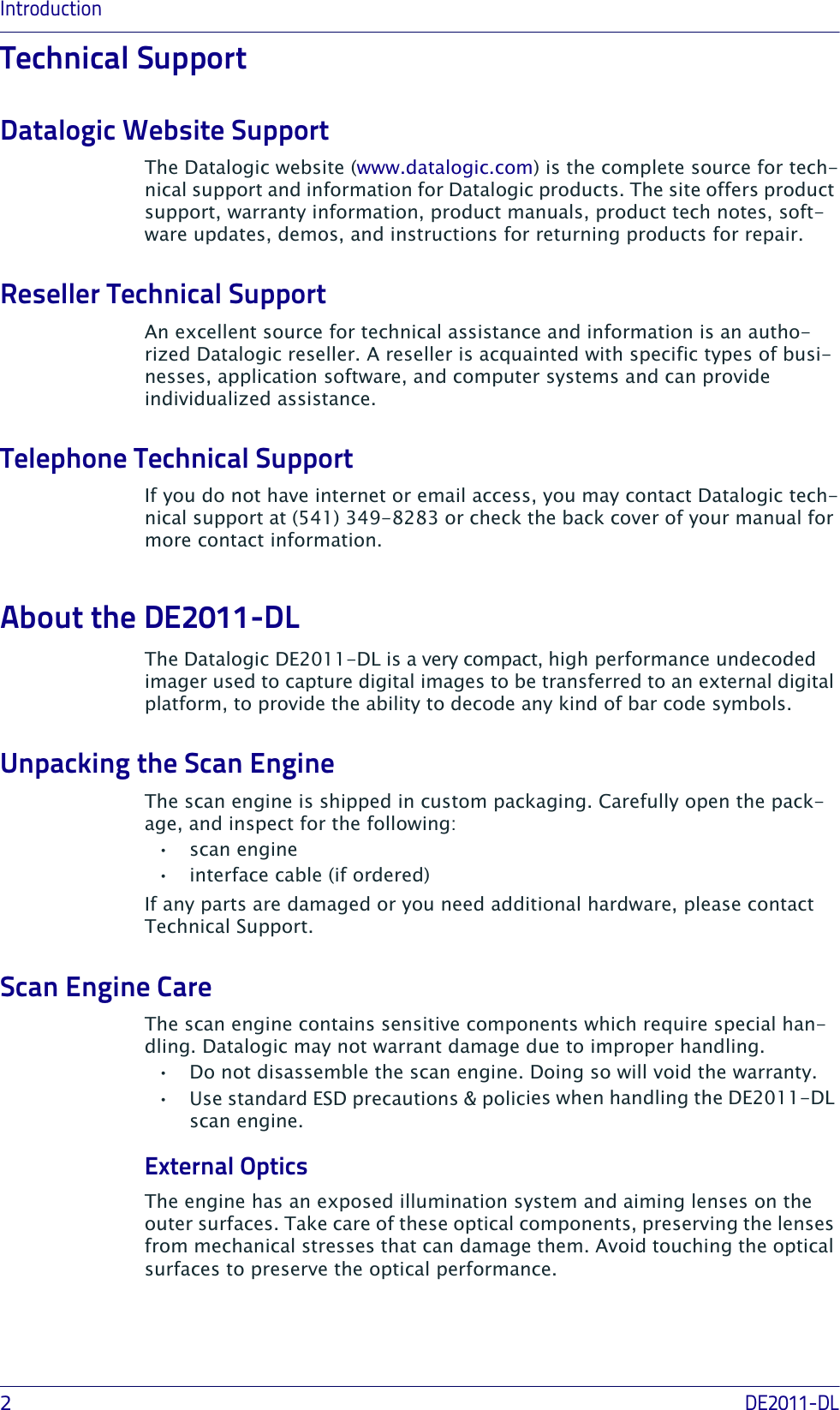


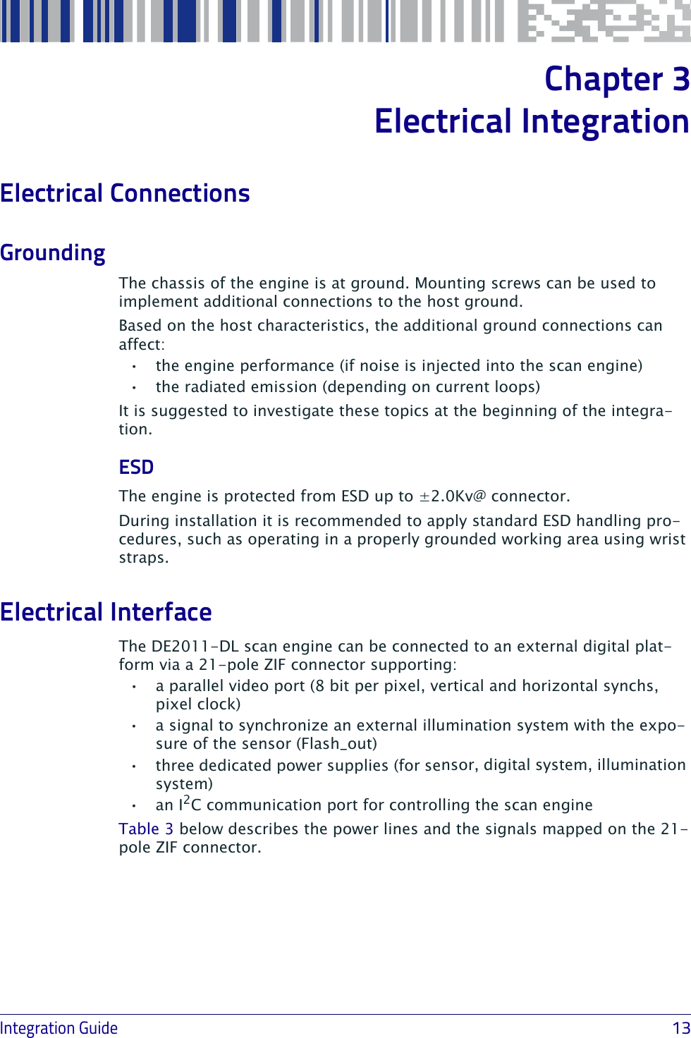
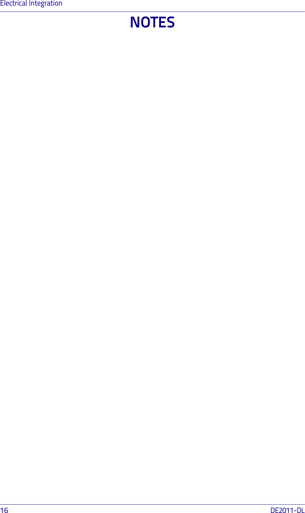
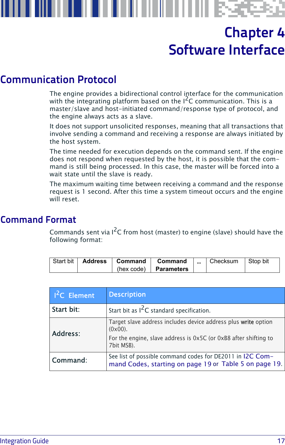
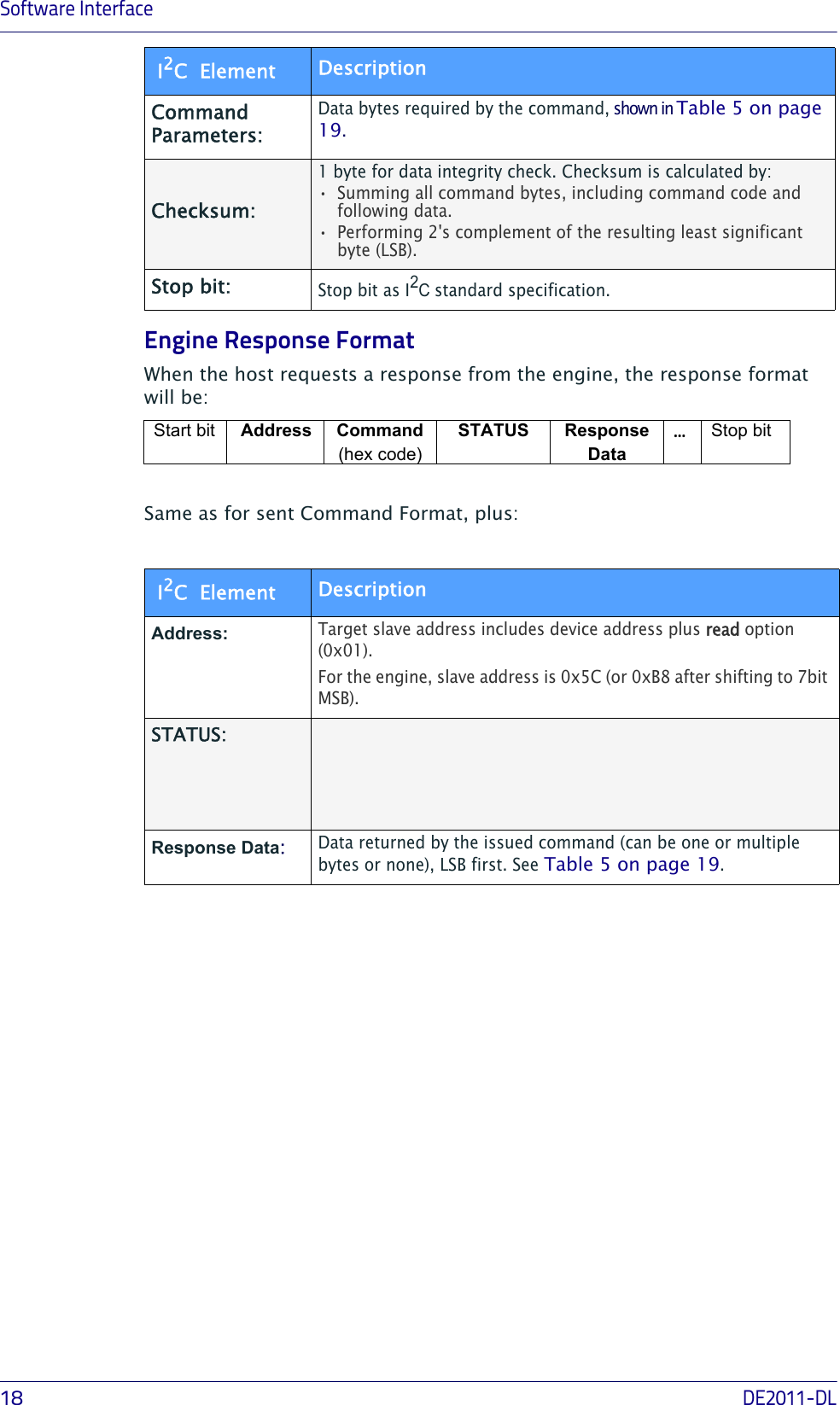
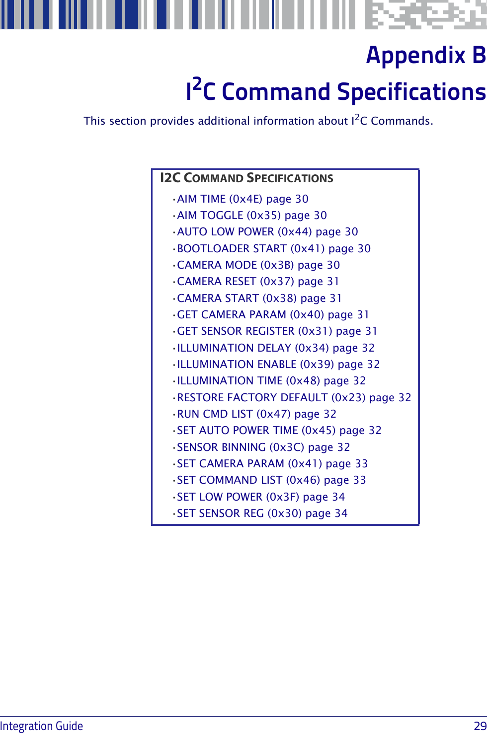
![Communication ProtocolIntegration Guide 19I2C Command CodesCommand ParametersThe following table shows a categorized list of the DE2011-DL possible I2C commands in hexadecimal code, including a brief description, with corre-sponding parameters and response bytes. All bytes are intended as Least Significant Byte (LSB) first, both in send and receive transactions.This table only describes the parameters to be used with each command, not including the checksum byte or STATUS response byte. For a complete description of the I2C protocol see "Communication Protocol" on page 17.For more information on the commands, see "I2C Command Specifications" on page 30.Default values are shown as underlined text in the following table.Table 5. Commands and response formatCmd Code Cmd Name Description Parameters Response Data (if present)CAMERA OPERATIONS[0x37] CAMERA RESET Resets system to initial state.1 Byte: 00=Sensor-Only Reset01=Full System Reset[0x38] CAMERA START Starts or stops image acquisition.1 Byte:0x00=Stop 0x01=Start[0x3B] CAMERA MODE Optimizes sensor configuration for different tasks.1 Byte:0=Barcode Decode1=Image Capture2=Motion Detect 3=Fast High Bin 4=LCD Read[0x42] BOOTLOADER STARTStops operations and starts bootloader.3 Bytes:Signature: 0xAA, 0x50, 0x5F[0x47] RUN CMD LIST Executes a user-defined sequence of commands.1 Byte:List# to run (0 – 10)[0x46] SET CMD LIST Sets a user-defined sequence of commands to be executed using RUN CMD LIST1 Byte:List# to run (0 – 10)+n Bytes (max 149):Command script(s)](https://usermanual.wiki/Datalogic-S-r-l/0060.Integration-Guide/User-Guide-2466404-Page-23.png)
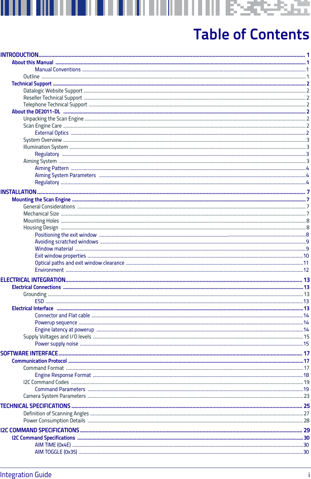
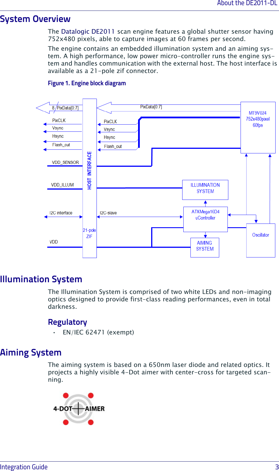
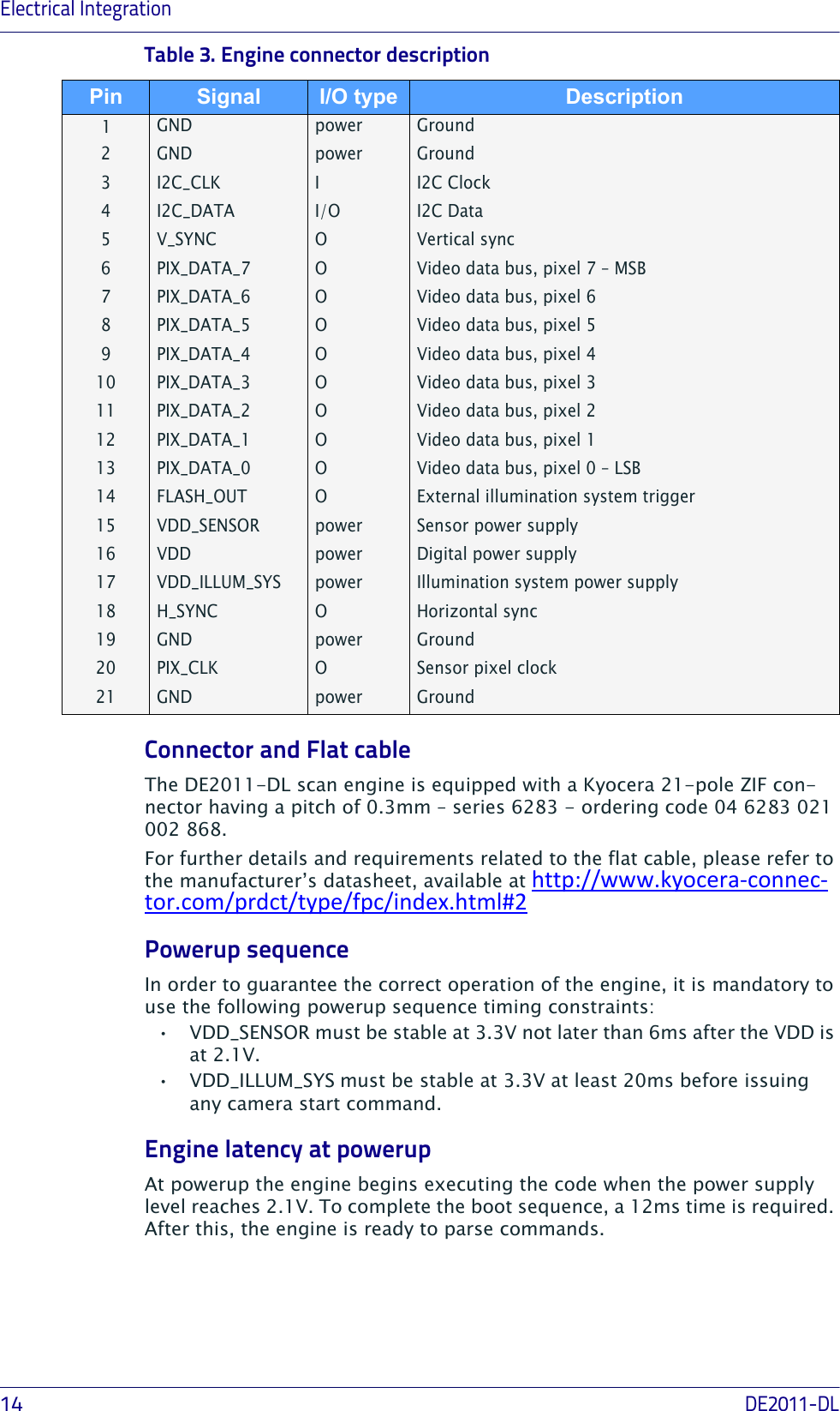
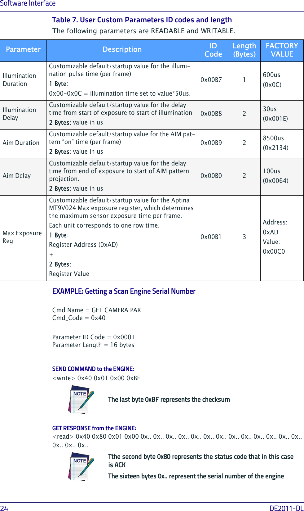
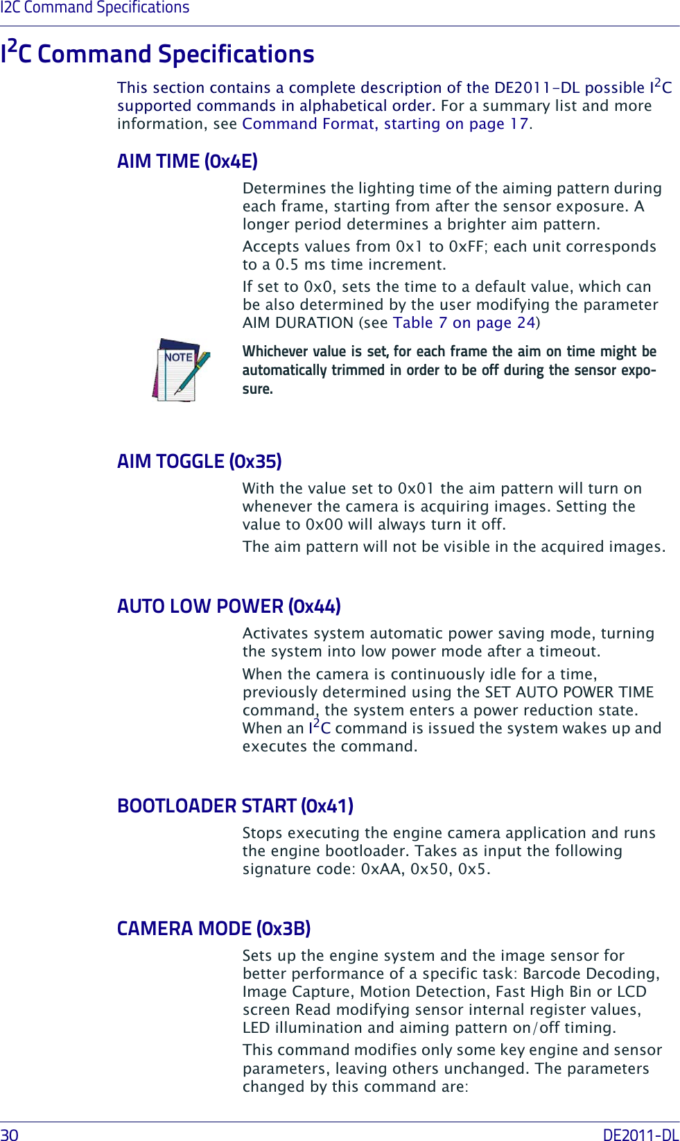
![Software Interface20DE2011-DLCAMERA SYSTEM CONFIG[0x23] RESTORE FACTORY DEFAULTclears Camera USER CUSTOM parameters, bringing them back to FACTORY DEFAULT values1 Byte: 00 [0x3F] SET LOW POWER Activates system power saving mode1 Byte:0x00=Normal0x01=Low Power[0x40] GET CAMERA PARAMReturns chosen Camera parameter (stored in EEPROM).2 Bytes:Parameter ID Coden Bytes:Parameter current value; number of bytes depending on parameter‡ [0x41] SET CAMERA PARAMSets desired value to chosen Camera USER CUSTOM parameter (stored in EEPROM).2 Bytes:Parameter ID Code+n Bytes:parameter data‡ 2 Bytes:Parameter ID Code [0x44] AUTO LOW POWERSystem automatic power saving mode.1 Byte:00=Disabled01=Enabled[0x45] SET AUTO POWER TIMESets the time to power saving mode when camera is idle (AUTO LOW POWER must be active).1 Byte:0x01 - 0x0A = 10-100 ms, 10 ms increments 0x0B - 0x14 = 100-900 ms, 100 ms increments 0x15 - 0xFF = 1s - 235 s, 1 s increments 0x00 = 5 msAIMING SYSTEM[0x35] AIM TOGGLE Switches the aiming system ON/OFF.1 Byte:00=Off01=On‡ See Table 6 on page 23 and Table 7 on page 24 for details on parameter length and ID code.Cmd Code Cmd Name Description Parameters Response Data (if present)](https://usermanual.wiki/Datalogic-S-r-l/0060.Integration-Guide/User-Guide-2466404-Page-24.png)
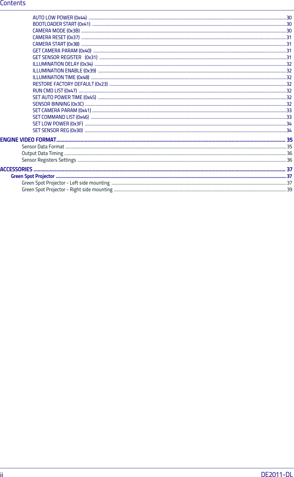
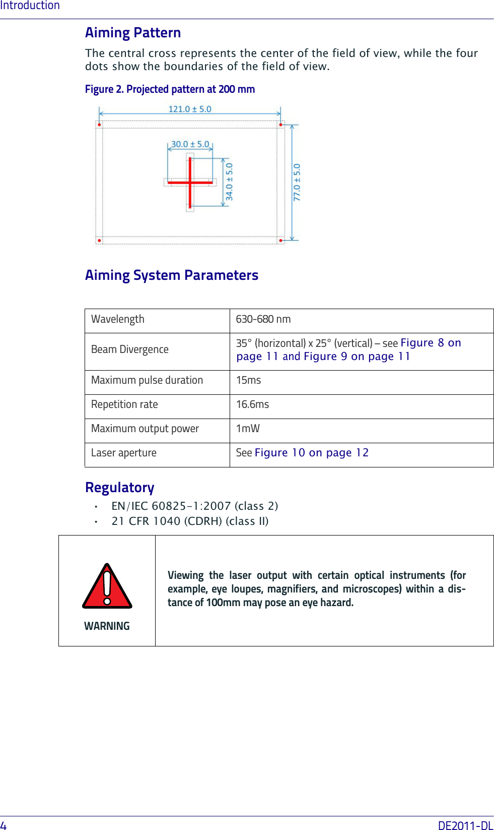
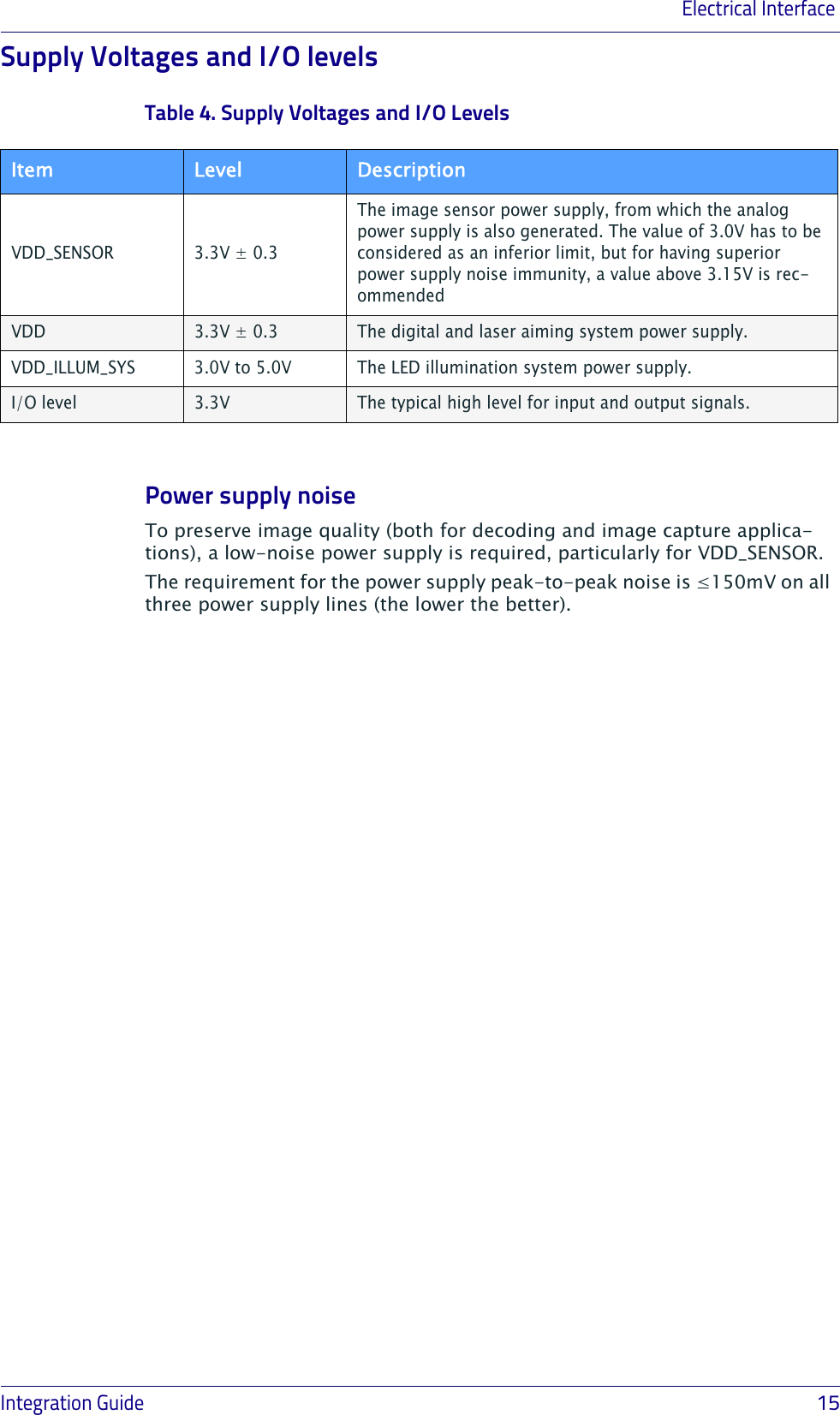
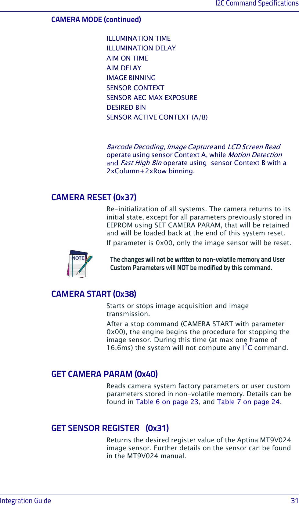
![Communication ProtocolIntegration Guide 21[0x4E] AIM TIME Sets the aim pattern lighting time for each frame (determines brightness).1 Byte:0x00 = sets Aim “on” time to default (=8500ms), o r t o user custom if previously modified. (per Frame)0x01-0xFF = aim “on” time set to value*0.5ms. (per Frame)Note: pulse duration can be trimmed by sensor exposure time variationsLED ILLUMINATION SYSTEM[0x34] ILLUMINATION DELAYSets the time from sensor exposure start to LED lighting start.1 Byte:0x00-0xFF = delay time from start of exposure to start of illumination set to value*30us.[0x39] ILLUMINATION ENABLESwitches ON/OFF the LED illumination system.1 Byte:00=Off01=On[0x48] ILLUMINATION TIMESets the illumination lighting time for each frame (determines brightness).1 Byte:0x00 = OFF0x01-0x0C = illumination time set to value*50us. (per Frame)IMAGE SENSOR[0x30] SET SENSOR REGWrites new value to the Aptina MT9V024 desired register.1 Byte:Register address+2 Bytes:Register new value[0x31] GET SENSOR REGGets Aptina MT9V024 desired register value.1 Bytes:Register address2 Bytes:Register current valueCmd Code Cmd Name Description Parameters Response Data (if present)](https://usermanual.wiki/Datalogic-S-r-l/0060.Integration-Guide/User-Guide-2466404-Page-25.png)
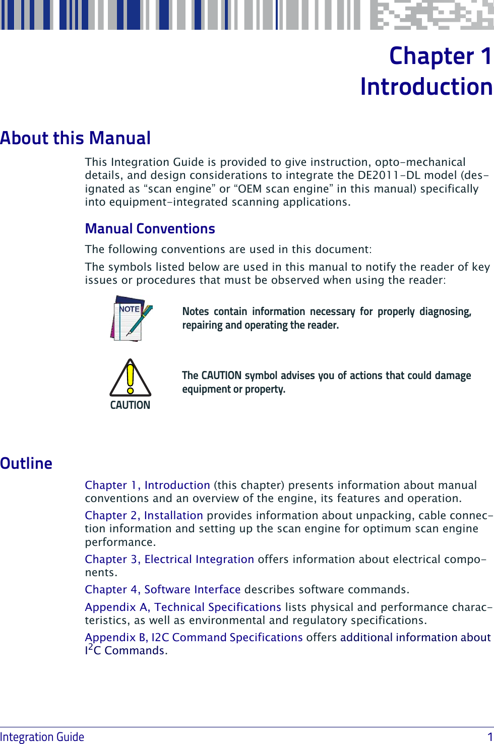
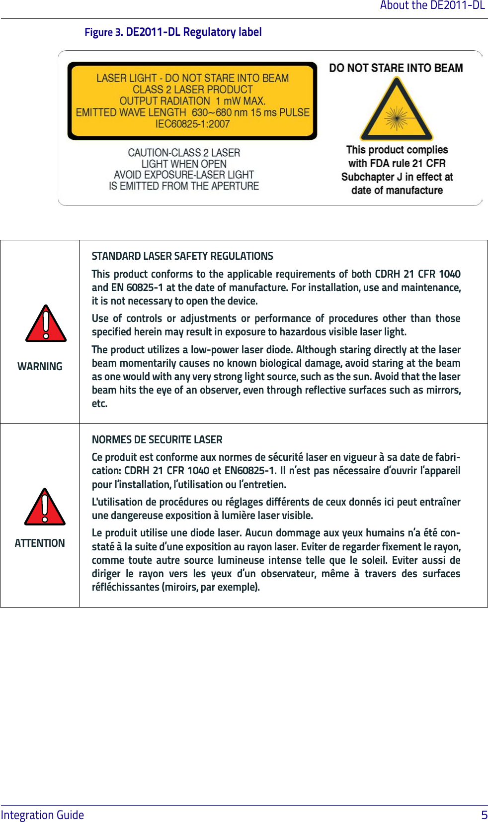
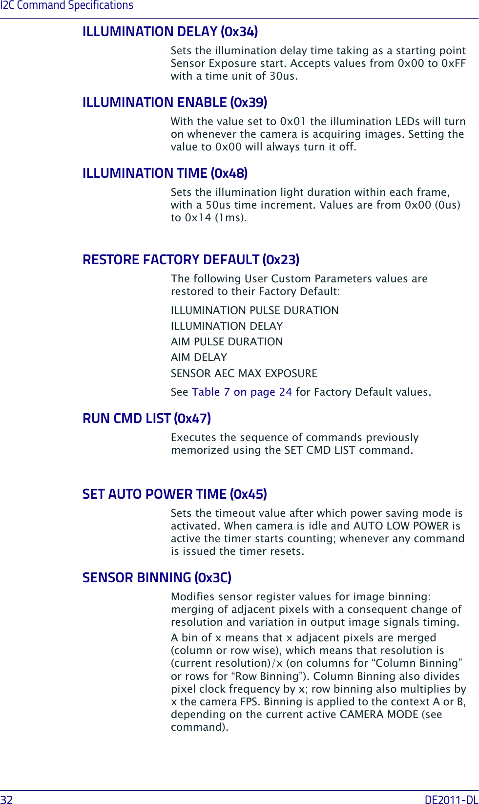
![Software Interface22DE2011-DL[0x3C] SENSOR BINNINGSets the binning operated by the Sensor.1 Byte:0x00=NormalRow binning codes: 0x00 = No Row Bin0x01 = Row Bin 2 0x02 = Row Bin 4Column Binning codes:0x00 = No Column Bin0 x04 = Column Bin 2 0x08 = Column Bin 4Resulting Parameter for Image Binning = (Row binning code) + (Column Binning code)Cmd Code Cmd Name Description Parameters Response Data (if present)See Table 6 on page 23 and Table 7 on page 24 for details on parameter length and ID code.](https://usermanual.wiki/Datalogic-S-r-l/0060.Integration-Guide/User-Guide-2466404-Page-26.png)
![Technical Specifications26DE2011-DLField of View 40° Hx26° VPrint Contrast Minimum 25% minimum contrastScanning AnglesSee Definition of Scanning Angles on page 27 for additional information.Roll Angle Up to ± 180°Pitch Angle ± 60°Skew Angle ± 60°Minimum Element Width1D Linear: 0.0762mm / 3mils PDF: 0.127mm / 5mils Datamatrix: 0.195mm / 7.5mils Symbology Resolution[mils]Dmin[mm]Dmax[mm]Dmin[mm]Dmax[mm]Code 39 380 175 85 130Code 39 555 260 70 220PDF 10(1)bb. Limited by field of view200 (1)b180EAN13 13 45 420 50 380Datamatrix 15 35 265 45 245Code 39 20 (1)b590 (1)b500Depth of Fieldaa. All labels grade A, ambient light level 300lux, pitch angle 10°, tilt angle 10°, skew angle 0°, room temperature 20°C. TypicalGuaranteedItem DescriptionUser EnvironmentOperating Temperature Operating : -30 to 50⁰C / -22 to 131⁰FStorage Temperature Storage / Transport : -40 to 70⁰C / -40 to 158⁰FHumidity (non-condensing) 95%Mechanical Shock2000 G ± 5% applied via any mounting surface at -30º and 70º C for a period of 0.85 ± 0.05 msec2500 G ± 5% applied via any mounting surface at 23º C for a period of 0.85 ± 0.05 msecAmbient Light Immunity Up to 100,000 Lux ESD Level ±2.0kV @ connectorItem Description](https://usermanual.wiki/Datalogic-S-r-l/0060.Integration-Guide/User-Guide-2466404-Page-30.png)
![I2C Command SpecificationsIntegration Guide 33SENSOR BINNING (continued)The parameter to be sent can be calculated by summing the number corresponding to the desired Row Binning, with the number corresponding to the desired Column Binning, as in the following table:Row Binning codes:0x00 = No Row Bin0x01 = Row Bin 20x02 = Row Bin 4Column Binning codes:0x00 = No Column Bin0x04 = Column Bin 20x08 = Column Bin 4Total Image Binning code = (Row Binning code) + (Column Binning code). A value of “0” disables Binning.SET CAMERA PARAM (0x41)Writes the chosen parameter to the camera’s non-volatile memory area User Custom Parameters. The stored values will be used as new defaults, replacing the Factory Default Values. For example, after a camera reset or startup the user custom values will be applied. The customizable parameters are:ILLUMINATION PULSE DURATIONILLUMINATION DELAYAIM PULSE DURATIONAIM DELAYSENSOR AEC MAX EXPOSURESee Table 7 on page 24 for details.To roll back the memory to factory default (losing the custom values), use RESTORE FACTORY DEFAULT command.SET COMMAND LIST (0x46)Sets a user-defined sequence of commands to be executed using RUN CMD LIST. Up to ten lists (0 to 9) can be saved; each can store up to 150 bytes (command codes + command parameters). NAK response is issued by the camera if limits are not respected. Possible commands for the list are:AIM TOGGLE CAMERA STARTILLUMINATION ENABLESET SENSOR REGCommand format:(0x46)(List#)(Total Length) + (Command1 Length) (Command1) +[…]+(Command n Length) (Command n) +(Checksum)Where “command x” is the normal byte sequence of the desired command.](https://usermanual.wiki/Datalogic-S-r-l/0060.Integration-Guide/User-Guide-2466404-Page-37.png)