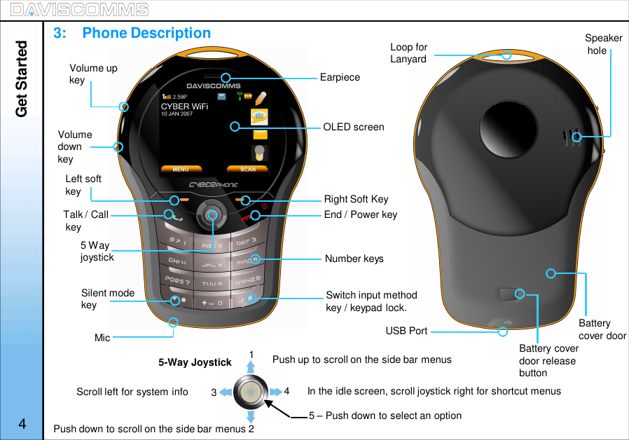
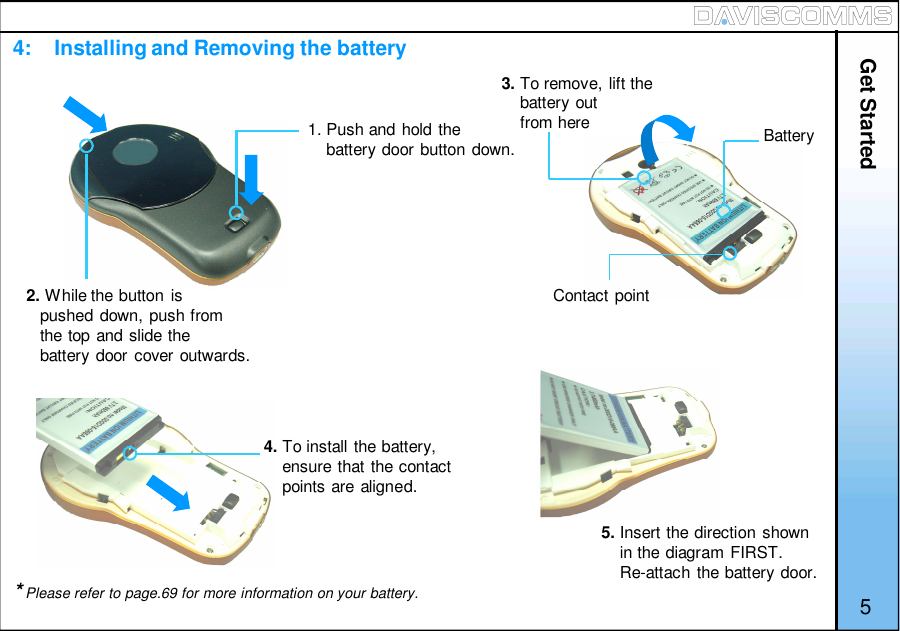
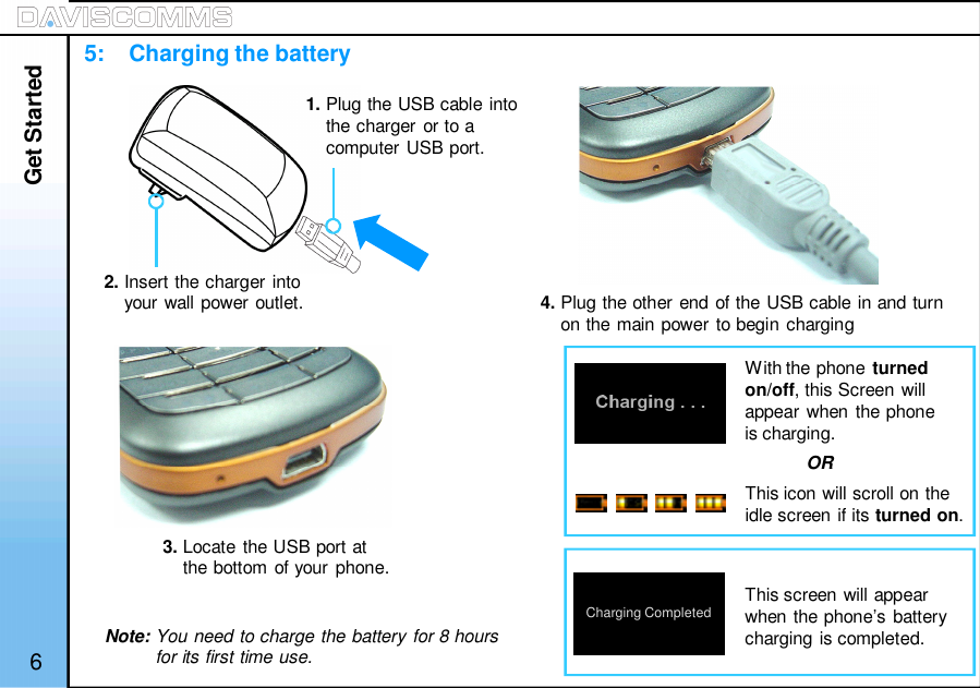
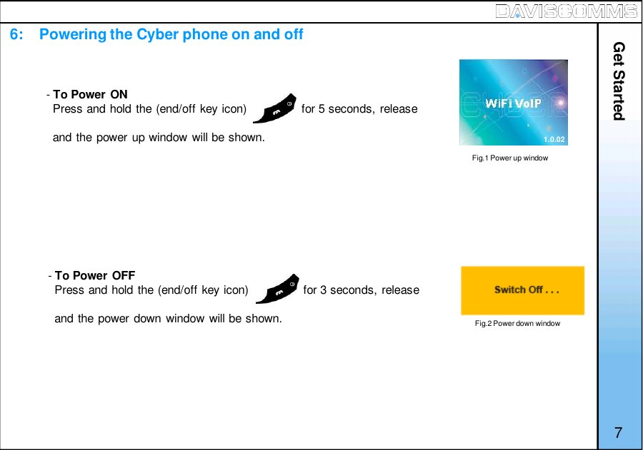
Daviscomms CYBER80211 802.11b/g VoIP WiFi SIP Phone User Manual manual

Daviscomms (S) Pte Ltd 802.11b/g VoIP WiFi SIP Phone manual

manual

Table of Contents1:  Get started . . . . . . . . . . . . . . . . . . . . . . 31.      Standard package contents . . . . . . . . . . .32.      Phone specification . . . . . . . . . . . . . . . . . 33.      Phone description . . . . . . . . . . . . . . . . . . 44.      Installing & removing the battery . . . . . . . 55.      Charging the battery . . . . . . . . . . . . . . . . 66.      Powering the Cyber phone on & off . . . . 77.      Display indicators & icons . . . . . . . . . . . . 88.      Shortcut menu . . . . . . . . . . . . . . . . . . . . . 99.      Main Menu icons . . . . . . . . . . . . . . . . . . . 102:   Configuring your phone . . . . . . . . 111.      Important information you shouldknow first . . . . . . . . . . . . . . . . . . . . . . . . . 112.      Connecting your phone to an AP . . . . . . .133.      Connecting your phone to an SIP . . . . . . 143:   Basic call functions . . . . . . . . . . . . 151.      Making a IP to IP call (via direct IP) . . . . .152.      Making a SIP to SIP call (via SIP server). 163.      Making a call (via SIP server to landlineor GSM mobile phone) . . . . . . . . . . . . . .  174.      Speed dial . . . . . . . . . . . . . . . . . . . . . . . . 185.      Answering a call . . . . . . . . . . . . . . . . . . . 186.      Mute/Un-mute a call . . . . . . . . . . . . . . . . .187.      Hold . . . . . . . . . . . . . . . . . . . . . . . . . . . . . 184:    Menu . . . . . . . . . . . . . . . . . . . . . . . . . . . 20i            Messages . . . . . . . . . . . . . . . . . . . . . . 201) Keypad legends. . . . . . . . . . . . . . . . .212) Create . . . . . . . . . . . . . . . . . . . . . . . .223) Inbox . . . . . . . . . . . . . . . . . . . . . . . . .234) Outbox . . . . . . . . . . . . . . . . . . . . . . . 255) Chat . . . . . . . . . . . . . . . . . . . . . . . . . 26ii            Contacts . . . . . . . . . . . . . . . . . . . . . . . 271) Add . . . . . . . . . . . . . . . . . . . . . . . . . . 282) Edit . . . . . . . . . . . . . . . . . . . . . . . . . . 283) Delete . . . . . . . . . . . . . . . . . . . . . . . . 294) View Entry . . . . . . . . . . . . . . . . . . . .  295) Speed Dial . . . . . . . . . . . . . . . . . . . . 29iii            Call Log . . . . . . . . . . . . . . . . . . . . . . . 301) Missed calls . . . . . . . . . . . . . . . . . . . 312) Incoming calls. . . . . . . . . . . . . . . . . . 313) Outgoing calls . . . . . . . . . . . . . . . . . .318.      New calls . . . . . . . . . . . . . . . . . . . . . . . . . 189.      Rejecting a call . . . . . . . . . . . . . . . . . . . . 1910.    Silencing the incoming ring tone . . . . . . . 1911.    Call waiting . . . . . . . . . . . . . . . . . . . . . . . 1912.    Conference call . . . . . . . . . . . . . . . . . . . . 191
iv            Settings . . . . . . . . . . . . . . . . . . . . . . . 321) Clock . . . . . . . . .  . . . . . . . . . . .  342) Wallpaper . . . . . . . . . . . . . . . . .  363) Ring tones . . . . . .  . . . . . . . . . .  364) Message tones . . . . . . . . . . . . . 375) Ring Volume . . . . . . . . . . . . . . . 376) Receiver volume . . . . . . . . . . .  377) Alert mode . . . . . . . . . . . . . . . .  388) Message View . . . . . . . . . . . . . 389) Brightness . . . . . . . . . . . . . . . .  3810) Key backlight . . . . . . . . . . .  . . 3911) Auto key lock . . . . . . . . . . . . . . 3912) Key tone . . . . . . . . . . . . . . . . .  3913) DTMF tone . . . . . . . . . . . . . . .  3914) Screen Banner . . . . . . . . . . . .  4015) Factory reset . . . . . . . . . . . . . . 4016) Software upgrade . . . . . . . . . . 41v:   Configuration . . . . . . . . . . . . . . . . . . . . . . . 451) SIP settings . . . . . . . . . . . . . . . . 462) IP settings. . . . . . . . . . . . . . . . .  493) WLAN settings . . . . . . . . . . . . . .52vi:   Information . . . . . . . . . . . . . . . . . . . . . . . . 561) SIP information . . . . . . . . . . . . . 562) IP information . . . . . . . . . . . . . .  563) WLAN information. . . . . . . . . . .  564) General information . . . . . . . . . 565. Web configurator. . . . . . . . . . . . . . 576. Glossary . . . . . . . . . . . . . . . . . . . . 677. Health and safety information . . . 688. FCC Declaration . . . . . . . . . . . . . . .712
1. Get Started1:    Standard Package ContentsPlease check carefully if you have the items mentionedbelow:1: WiFi Phone x 012: USB Charger x 013: USB Cable x 014. Battery x 015. User’s Manual x 016. Lanyard Strap*Actual contents may vary.2:    Phone SpecificationsDimensions: 96(L) x 65(W) x16(H) Dimension inmm.Weight: 65g (without battery)80g (with battery)Battery: 650 mAh Li-ion,3.7vCharger Input: 100-240v – 50-60Hz0.2ACharger Weight: 50gCharging Time: 3 hoursStandby Time: 48 hours dependingon the networkTalking Time: 2 hours dependingon the network 3The CYBERPHONE is a 802.11b/g VoIPWiFi SIP Phone.Get Started
Get Started43:    Phone DescriptionEarpieceOLED screenRight Soft KeyEnd / Power keyNumber keysSilent modekeyLeft softkeyVolume upkeyVolumedownkeySwitch input methodkey / keypad lock.Talk / Callkey5 WayjoystickUSB Port Batterycover doorLoop forLanyardSpeakerhole5-Way Joystick 12345 – Push down to select an optionBattery coverdoor releasebuttonMicScroll left for system info In the idle screen, scroll joystick right for shortcut menusPush up to scroll on the side bar menusPush down to scroll on the side bar menus
4:    Installing and Removing the battery1. Push and hold thebattery door button down.2. While the button ispushed down, push fromthe top and slide thebattery door cover outwards.BatteryContact point3. To remove, lift thebattery outfrom here4. To install the battery,ensure that the contactpoints are aligned.5. Insert the direction shownin the diagram FIRST.Re-attach the battery door.Get Started*Please refer to page.69 for more information on your battery. 5
Get Started65:    Charging the battery2. Insert the charger intoyour wall power outlet.1. Plug the USB cable intothe charger or to acomputer USB port.3. Locate the USB port atthe bottom of your phone.4. Plug the other end of the USB cable in and turnon the main power to begin chargingWith the phone turnedon/off, this Screen willappear when the phoneis charging.This screen will appearwhen the phone’s batterycharging is completed.ORThis icon will scroll on theidle screen if its turned on.Charging CompletedNote: You need to charge the battery for 8 hoursfor its first time use.
Get Started76:    Powering the Cyber phone on and off-To Power ONPress and hold the (end/off key icon)                for 5 seconds, releaseand the power up window will be shown.-To Power OFFPress and hold the (end/off key icon)                for 3 seconds, releaseand the power down window will be shown.Fig.1 Power up windowFig.2 Power down window1.0.02
Get Started87:    Display indicators and icons Received signal strength from WiFiaccess point.Time displayCall mute (Un-mute, Mute)Keypad lockWrite MessageThe roles of the soft keys vary depending on thefunction you are using. The keys just belowselects the functions desired when pressed.NOTE:If you are disconnected from the signal,the right soft key will automatically changeto the “SCAN” selection.2.59PTo lock, press and hold             for 1 second.To unlock, press and hold             for 1 second.(Weak Strong)(Weak Strong)Message Inbox (new, read, sent, not sent)Message IconChat IconSoft key function indicatorsWiFi connectivity status (refer to pg.12)Alert type (ring, ring and vibrate, silent,vibrate only)Battery level indicatorRecent Calls IconIdle Screen
Site ScanSIP RegistrationReload IPRestart WLANWeb ConfiguratorSystem info provides a summary of the connection details your phone to the network AP.WLAN :Displays the name of the AP you are connected to.IP address : Displays the IP address assigned to the phone.User Name : Displays the User name used for SIP connection.Proxy Server : Displays the IP address of the proxy server the phone is connected to.Outbound proxy : Displays the outbound proxy address of the SIP server the phoneis connected to.8. Shortcut MenuShortcut menu allows a quick access to the configuration setting menu of your phone.System Info9BACK: Allows you to scan and join the list of APs available in your network LAN: Allows you to activate or reconnect your SIP account on the Cyber WiFi phone: This function allows you to request an IP address from a DHCP server: This function restarts the phone’s wireless connection to the AP.: This function allows you to configure your phone settings using a web browser.Get Started
Get StartedIndividual icons will illuminate when selected. Navigate your way around the icons by moving thejoystick. Press the joystick down to select the application.Message: Use the messages menu to send and receive short messages.Contacts: Store and find from a list of contacts stored in your contact list.Call Log: Views the calls you have dialed, received, or missedSettings: Settings menu provides you with various setting options to customize the phone to yourpreferences and needs. You can also reset the setting to their default values.Config: Use this menu to configure the SIP, IP and WLAN settings.Info: Use this menu to check the information of your SIP, IP, WLAN and General settings.109:    Main Menu Icons
2. Configuring your phone1:    Important information you should know first-Possible ways of communicating using the CYBERPHONE.- IP to IP call- SIP to SIP callNote: You will need to subscribe with a SIP service provider to make a SIP call.For reference please refer to www.daviscomms.com.sg-Requirements in order to establish a communication on the CYBERPHONE.- The phone must be associated to an AP in order to communicate to other WiFi phones.Note: - Do take note that there are some network security protocols installed on the LAN which youwish to connect to.- Some require registering the MAC address of the CYBERPHONE in order to allow access tothe AP of the network. Under such circumstances, you should seek assistance from yournetwork administrator to register the MAC address of the phone to the server to gain access to thenetwork’s AP.-Encryption- Connecting the CYBERPHONE to wireless LAN area may require anencryption password. You will need this password to gain access to the network in order toassociate to the AP you are connecting to.- Most standard network uses WEP-64 encryption protocol. You would need to consult your networkadministrator if the network uses other settings. 11Configuring Your Phone
12-SIP Server connection- A SIP connection allows you to communicate to another SIP user via a WiFi phone without havingthe hassle to remember the full length of the IP address number.Note: - Before you can connect to a SIP server, it is necessary that you obtain a SIP account. You canalso obtain a paid SIP account which provides you communication to a mobile phone number (GSM)or a landline number (PSTN).For reference please refer to www.daviscomms.com.sg-Connectivity Status-The connectivity status of your CYBERPHONE must be green in order for your phone to make calls.Below is the illustration of the connectivity status of your CYBERPHONE.Configuring Your PhoneRed – Not connected to an AP.Amber – It is connected to an AP but no IP is being assigned.Green – Connected to an AP and IP is being assigned.
2:    Connecting your phone to an AP13Auto Connecting to an APBefore you proceed to making a call, you will first need the CYBERPHONE to connect to an AP.Your phone will automatically detect and connect to your pre-configured AP on the first power up.Manually setting up the phone to connect to an AP in your LAN networkStep.1 - From the idle screen, select > MENU > CONFIG > WLAN > SSID >SCAN within your area, a listof available AP’s will appear >scroll and select the AP you wish to connect to, select > VIEW> Select the AP you like to join.Step.2 - In the same WLAN settings menu, select > ENCRYPTION >scroll and select > WEP-64. ( Please refer to pg.10, on encryption. )Step.3 - In the WEP-64 screen, select >OPEN SYSTEM> ( Please confirm thissetting with your Network Administrator. ) and select > KEY 1.Step.4 - Input the password encryption of the AP set by your network administrator >when done, select >OK > in the WLAN Settings menu, select ACTIVATE by pressing the left soft key              .Note:-1.) Wait for the connectivity status bar to turn green. The main screen will display “Connecting AP….” followed by “Connecting IP….” to complete the connection the to the network If the connecting AP disappearsand connectivity is still red, retry. If you still have problems, consult your IT administrator for the network details.2.) Incase of WEAK SIGNAL, there will be an alert tone & display showingStep.5 – Once your phone connectivity status turns greenYou should be able to make a call via direct IP to IP.Configuring Your PhoneFig.4 Calling ScreenFig.3 Poor Signal CoverageScreen
3:    Connecting your phone to an SIPOPTIONS HANDFREE14Note: - Before you proceed to making a call, you will first need to set up the CYBERPHONE toregister to a SIP server connection.For reference please refer to www.daviscomms.com.sgStep.1 - From the idle screen, select > MENU > CONFIG > SIP > USER NAME > input your user nameaccording to your SIP account details and select > OK.Step.2 - In the same SIP settings menu, select > PASSWORD > input your password according to yourSIP account details and select > OK.Step.3 - In the same SIP settings menu, select > PROXY SERVER > IP ADDRESS > key in the addressof your SIP server, for example, > SIPprovider.org and select > OK.Step.4 - In the Proxy Server settings menu, select > STATUS > and select > ENABLE.Step.5 - Go back to the SIP settings menu, select > OUTBOUND PROXY > IP ADDRESS > key in theIP address of your SIP server, for example, > SIPprovider.org and select > OK.Step.6 - In the Outbound Proxy settings menu, select > STATUS > and select > ENABLE.Step.7 - Go back to the SIP settings menu, select > ACTIVATE by pressing the left soft key              .Note: - After activating, a “Registering SIP…” display will be appear at the Idle screen.The “Not Registered” sign will disappear on the idle screen to indicate that yourCYBERPHONE is connected to your SIP server account.Step.8 - You are now ready to make a SIP to SIP call via SIP server.Configuring Your Phone
Basic Call FunctionsFor eg:- 1234567@191.166.123.203Note: Please make sure to disable the SIP settings before making an IP to IPcall. To do so, please follow the steps below:Disabling SIP - Go to MENU > CONFIG > SIP > PROXY SERVER > STATUS >select DISABLE > select BACK > OUTBOUND PROXY > STATUS >select DISABLE > select BACK > ACTIVATE by pressing the left softkey             .Step.1 - In the idle screen, key in the number, for eg:-1234567@191.166.123.203Step.2 - Press            and “calling 1234567@191.166.123.203” will be displayed.Step.3 - When the call is connected, call timer will be displayed.Step.4 - To end the call, press the             key.Note: “@” is keyed by pressing              key twice.Fig.5 Calling ScreenFig.6 Call timer screenThese figures are definedby the recipient’s user nameIn the SIP settings.These figures refers to recipientsFIXED IP numberOPTIONS153. Basic Call Functions1:    Making an IP to IP call (via direct IP)SPEAKERSPEAKER
Basic Call FunctionsOPTIONS HANDFREEFor eg:- 31080240Step.1 - Key in the SIP contact numberStep.2 - Press            and “calling 31080240 will be displayed.Step.3 - When the call is connected, call timer will be displayed.Step.4 - To end the call, press the              key.These figures will be the other parties SIPphone number you wish to dial.16Note: A user can only call to the other party via the same SIP provider. Please refer to your SIPprovider’s agreement if you are contacting another person of another SIP provider account.Do make sure that your SIP settings are activated. (Refer to Pg.14)2:    Making a SIP to SIP call (via SIP server)
3:    Making a call ( via SIP server to Landline / GSM Mobile Phone)Basic Call FunctionsNote: For eg:- 65 62100123Step.1 - Key in the number, for eg:- 6562100123Step.2 - Press            and “calling 6562100123” will be displayed.Step.3 - When the call is connected, call timer will be displayed.Step.4 - To end the call, press the             key.Country code Land line numberor mobile numberNote: You can only call a Landline / GSM Mobile phone line depending on your SIP Server accountservices.For reference please refer to www.daviscomms.com.sgDo make sure that your SIP settings are activated. (Refer to Pg.14)17
4:    Speed dial5:    Answering a call6:    Mute/Un-mute a Call7:    Hold8:   New Calls- Refer to page.29 for the setting up of speed dial.- During standby mode, press and hold the preset key for 1 second to displaythe name and phone number, press left              soft key to call.- Press the             key to answer incoming calls. Call timer will be displayed.Basic Call FunctionsSILENTFig.7 Incoming call screen18- During a call is answered, click on options> scroll to mute and click select.To un-mute the call, click on options> scroll to mute and click select.During a call you can put the other party to hold by clicking on options> scroll to Hold and click select.New calls allows you to connect to another user while having one conversations active at the same time.To create a new call, click on options during a call> scroll to New call > click select> Key in number orselect Contacts> click CallSPEAKER
- When there is an incoming call, press the              key to reject the call.- Number of missed calls will be displayed. Press the left soft             key toview the missed call.9:    Rejecting a call10:   Silencing the incoming ring tone11:   Call waiting12:  Conference CallFig.8 Missed call screen- When there is a incoming call, press the left              soft key >select SILENT.Fig.9 Hold call screen- When another call comes in during a call, it will give a waiting tone.- To reject the incoming call, press the left              soft key >select REJECT.- To answer, press the             .Basic Call FunctionsVIEW EXIT19During a call, click on OPTIONS during a call >scroll to NEW CALL > click SELECT >key in a phone number or select CONTACTS > click CALL > when third party answers,click OPTIONS > and select a phone number.
Menu - Message204. MenuMenu – ( i ) MessagesCreate Allows you to create messages and send it to another party.Inbox and Outbox Allows to you view, edit and delete the messages.- Read Allows you to read the messages.- Reply Allows you to reply the messages you read.- Forward Allows you to forward the message you read to another party.- Delete Allows you to delete the message you select.- Delete All Allows you to delete all messages.Chat Allows you to create a chat session with another recipient.
Menu - Message21( 1 )    Keypad LegendsPress once to change betweenABC (uppercase), abc (lowercase)and 123 (numeric)Press repeatedly to scrollthrough various punctuations.Press once for SPACEand LONG PRESSfor “+”Press repeatedly to scrollbetween ( . @ :     )Hold to display the symbol tablePress repeatedly to scroll throughthe corresponding letters.
( 2 )    Create- Select MENU > MESSAGES > CREATE > type the message >select OK >key in a phone number and select > OK. OR select CONTACTS to pick anexisting contact in your phonebook and send.Note: You can also select MESSAGES from the idle screen by scrolling up ordown with the joystick and selecting it by pressing the center of the joystick.Press the            key to switch the text mode between “ABC”, “abc” and “123”.- ABC – Uppercase- abc – Lowercase- 123  – NumericMenu - MessageFig.10 Write Message ScreenOK BACKTip:You can create new messages or check your message inbox byselecting the          icon or the            icon at the idle screen.22
( 3 )    InboxInbox:     ReadInbox:     ReplyInbox:     Forward- Select MENU > MESSAGE > INBOX.Note: You will be notified if there is a new message in your inbox from the idle screenby spotting the           icon at the top of the idle screen.Note: Messages in the Inbox can be viewed. The arrangement of messages islatest (TOP) to earliest (BOTTOM)These are the following menus found when you access the INBOX.- From the MESSAGES menu >Select INBOX >Select the message you want toread >press the center of the joystick           to open the message to read.- From the MESSAGES menu >select INBOX>select the message you want toreply > OPTIONS > REPLY.- From the MESSAGES menu >select INBOX>select the message you want toforward > OPTIONS > FORWARD.Menu - MessageYES NO23Fig.11 Delete Message Screen
Menu - MessageInbox:     DeleteInbox:     Delete All- From the MESSAGES menu >select INBOX>select the message youwant to delete > OPTIONS > DELETE > select YES to confirm or NO tocancel.- From the MESSAGES menu >select INBOX > OPTIONS > DELETE ALL>select YES to confirm or NO to cancel.Note: All messages will be deleted permanently.YES NOFig.12 Delete All Message Screen24
Menu - Message( 4 )    OutboxOutbox:     ReadOutbox:     ForwardOutbox:     DeleteOutbox:     Delete All- Select MENU > MESSAGE > OUTBOX >Note: Messages in the Inbox can be viewed. The arrangement of messages islatest (TOP) to earliest (BOTTOM).- From the MESSAGES menu >Select OUTBOX >Select the message youwant to read >press the center  of the joystick            to read the message.- From the MESSAGES menu >select OUTBOX > select the message youwant to forward > OPTIONS > FORWARD.- From the MESSAGES menu >select OUTBOX > select the message you want todelete > OPTIONS > DELETE > select YES to confirm or NO to cancel.- From the MESSAGES menu >select OUTBOX > OPTIONS >DELETE ALL > select YES to confirm or NO to cancel.Note: All messages will be deleted permanently.Fig.13 Delete Message ScreenFig.14 Delete All Message ScreenYES NOYES NO25
( 5 )    ChatNote: The chat session can function on a IP to IP connectionor a SIP to SIP connection.Please check with your SIP provider if their service supportmessaging capability.- Select MENU > MESSAGES > CHAT- Enter the phone number of the recipient which you want the CHATsession to be associated with.- Contacts can be retrieved from the phonebook. Select OK.- For e.g:- INVITING 12345678 @ xxx.xxx.xxx.xxx will be displayedin the screen.- Once the chat request has been accepted by the recipient, chat sessioncan take place.Note: “YOU” Indicates the message you have received.“ I “ indicated the message you have sent.Menu - MessageFig.15 Banner Screen - ChatMENU CONTACTS26CANCELFig.16 Chat Session Invitation ScreenFig.17 Chat ScreenSEND CLEAR
Menu - Contacts27Add Allows you to add a new contact into your contact list.Edit Allows to you edit the contact which is stored in your contact list.Delete Allows you to delete a contact permanently from your contact list.Speed Dial Allows you to set a particular contact to a numeric key on your keypad.Adding a Contactfrom Idle Screen Allows you to add a new contact directly from the idle screen.Menu – ( ii ) Contacts
( 1 )    Add( 2 )    EditTo add from Contacts:- Select MENU > CONTACTS > OPTION > ADD > ( Input name ) > OK( Input Phone Number ) > OK.To add from Call Log:- Select Call Log > select either Missed Calls,Incoming Calls or Outgoing Calls>highlight the number, select OPTION > SAVE > ( Enter name ) > APPLY.To add from Idle Screen:From the idle screen, key in the number of the CONTACT > click SAVE > Input thename of the Contact > Click OK once done.Note: “Replace existing entry?” will be displayed if there is an existing contact.Note: You can also select         Recent Calls from the idle screen by scrollingup or down with the joystick and selecting it by pressing the center of thejoystick          .- Select CONTACTS > select the person you want to edit > OPTION > EDIT >enter name > OK>enter number > OK. to confirm.Fig.18 CONTACT SelectedFig.19 CALL LOG SelectedFig.20 Idle Screen – Call LogMENU CONTACTS28Menu - Contacts
( 3 )   Delete( 4 )    View Entry( 5 )     Speed Dial- Select CONTACTS > select the person you want to delete > OPTION > DELETE > select YES todelete or NO to cancel.- Select CONTACT > select a contact from the list > push joystick button            down to VIEW.- Select CONTACTS > select a contact from the list > OPTION >SPEED DIAL>SET.- To Unset, scroll to the Key number and press UNSET.- If you have a contact under key.1, in the idle screen, hold the                key and itwill dial the contact which you have assigned it with. Fig.21 Speed Dial ScreenSET BACK29Menu - Contacts
Menu – Call Log30Missed CallsIncoming CallsOutgoing CallsMenu – ( iii ) Call LogRecent CallsShows you the list of the numbers you have called, received ormissed picking up their call. Selecting the particular contact allowsyou to save the particular contact in your list, delete or delete allcontacts.Shows you the summary  list of the your outgoing, answeredor missed calls.Recent Calls
- Select MENU > CALL LOG  > MISSED CALLS.To Save, Delete or Delete All, select an entry and select OPTIONS.Note: Missed call list will appear from latest (top) to earliest (bottom).- Select MENU > CALL LOG  > INCOMING CALLS.To Save, Delete or Delete All, select an entry and select OPTIONS.Note: Incoming call list will appear from latest (top) to earliest (bottom).Menu – Call Log( 1 )    Missed Calls( 2 )    Incoming CallsFig.22 Call Log SelectedFig.23 Missed Call ScreenOPTION BACK31( 3 )    Outgoing Calls- Select MENU > CALL LOG  > OUTGOING CALLS.To Save, Delete or Delete All, select an entry and select OPTIONS.Note: Outgoing call list will appear from latest (top) to earliest (bottom).
Menu - Settings32Clock Allows you change the time, date and its formats.- Set Time Allows you to set the time which will be displayed on the idle screen- Set Date Allows you to set the date which will be displayed on the idle screen.- Time Format Allow you to set the time format to be 12 or 24 hours.- Date Format Allows you to set the date format to DD/MM/YY or MM/DD/YY.Wallpaper Allows you to change the wallpaper in the idle screen.Ring Tones Allows you to change the incoming call ring tones.Message Tones Allows you to change the alert tones for incoming messages.Ring Volume Allows you to set the ring volume from low to high.Receiver volume Allows you to set the volume of your receiver from low to high.Alert Mode Allows you to set your alert to Silent, Vibrate, Melody and Melody and Vibrate.Message View Allows you to view message list based on contacts or message itselfBrightness Allows you to view message list based on contacts or message itselfMenu – ( iv ) Settings
33Menu - SettingsKey Backlight Allows you to set the keypad light to stay Off, after 10, 20 or 30 seconds.Auto Key Lock Allows you set the Auto Key Lock feature to off, 30secs, 1min and 2mins.Key Tone Allows you turn the key tone On or Off when the keys are pressed.DTMF Tone Allows you to set the DTMF tone to inbound or outbound.Screen Banner Allows you to type in a banner message in the idle screen.Factory Reset Allows you to set the entire phone back to its original factory settings. Thephone will power off automatically.Software upgrade: Allows you to update the phone’s software of the phone to optimize itsperformance
Menu - Settings34Format: HH/MM = HOUR/MINUTE- Select MENU > SETTINGS > CLOCK > SET TIME > key in the currenttime.Fig.25 Time Setting Screen( 1 )    ClockClock:     Set TimeFig.24 Setting SelectedOK BACK
Menu - Settings35Format: DD/MM/YYYY   = DAY / MONTH / YEAR- Select MENU > SETTINGS > CLOCK > SET DATE and key in the currentdateFig.26 Date Setting ScreenClock:     Set DateOK BACK
- Select MENU > SETTINGS > CLOCK > TIME FORMAT > select either12 Hour or 24 Hour and choose SELECT.- Select MENU > SETTINGS > CLOCK > DATE FORMAT >select eitherDD / MM / YY or MM / DD / YY and choose SELECT.- Select MENU > SETTINGS > WALLPAPER > select the wallpapers of yourpreference by scrolling the joystick in any direction, and choose SELECT.- Select MENU > SETTINGS > RING TONES > select the ring tone of yourpreference by scrolling the joystick up or down         , a preview of the ringtone you choose will be played. Choose SELECT to set.Fig.27 Time Format  Setting ScreenClock:     Time FormatClock:     Date Format( 2 )    Wallpaper( 3 )   Ring Tones Fig.28 Date Format  Setting ScreenFig.29 Ring Tone  Setting ScreenSELECT BACKSELECT BACKSELECT BACKMenu - Settings36
Menu - Settings37- Select MENU > SETTINGS > MESSAGE TONES > select the ring tone of yourpreference by scrolling the joystick up or down         , a preview of the messagetone you choose will be played. Choose SELECT to set.- Select MENU > SETTINGS > RING VOLUME > increase or decrease thevolume by scrolling either direction of the joystick >choose SELECT to set.- Select MENU > SETTINGS > RECEIVER VOLUME > increase or decrease thevolume by scrolling either direction of the joystick >choose SELECT to set.Fig.30 Message Tone Setting Screen( 4 )    Message Tones( 5 )    Ring Volume( 6 )    Receiver VolumeFig.31 Ring Volume Setting ScreenFig.32 Receiver Volume Setting ScreenSELECT BACKSELECT BACKSELECT BACK
- Select MENU > SETTINGS > ALERT MODE > select the alert mode of yourpreference by scrolling the joystick up or down         , choose SELECT to set.Note: The following alert icons will appear on the idle screen depending on your selection.Ring Only:Vibrate Only:Ring and Vibrate:Silent:- Select MENU > SETTINGS > MESSAGE VIEW > to view message throughSearch name or Message itself. choose SELECT to set.- Select MENU > SETTINGS > BRIGHTNESS > select the intensity ofyour preference by scrolling the joystick up or down         ,choose SELECT to set.Fig.33 Alert Mode Setting Screen( 7 )     Alert Mode( 8 )    Message View( 9 )    BrightnessFig.35 Key Backlight Setting ScreenSELECT BACKSELECT BACKMenu - Settings38Fig.34 Message View Screen
Menu - Settings39- Select MENU > SETTINGS > KEY BACKLIGHT > select the backlight timer ofyour preference by scrolling the joystick up or down         , choose SELECTto set.- Select MENU > SETTINGS > AUTO KEY LOCK > select the key lock timer ofyour preference by scrolling the joystick up or down         .Choose SELECT to set.- Select MENU > SETTINGS > KEY TONE > select ON or OFF>choose SELECT to set.-Select MENU > SETTINGS > DTMF TONE > select INBAND,OUTBAND (Sip Info) or OUTBAND (RFC 2833) >choose SELECT to set.Note: DTMF (Dual Tone Multiple Frequency)Fig.37 Key Lock Setting Screen( 10 )    Key Backlight( 11 )   Auto Key Lock( 12 )   Key Tone( 13 )   DTMF ToneSELECT BACKFig.36 Key Backlight Setting ScreenFig.38 DTMF tone setting
Menu - Settings40- Select MENU > SETTINGS > SCREEN BANNER > key in your message,>choose OK to set.Note: You can input up to a maximum of 12 Characters.- Select MENU > SETTINGS > FACTORY RESET > choose YES to reset,or NO to cancel.Note: The phone will reboot and turn off.Fig.40 Banner Message( 14 )     Screen Banner( 15 )      Factory ResetFig.41 Factory Reset ScreenAPPLY CLEAROK BACKFig.39 Banner Message at Idle Screen
Note: During the Software upgrading, in your computer, make sure that under CONTROL PANEL >NETWORK CONNECTION, the Local Area Connection of the CYBERPHONE is present.Please also take note of the IP address at the startup screen You should only start yourTFTP program after this.Important: Do not disconnect the phone from the PC while it is in firmware upgrading progress.Doing so will permanently damage the phone.- To upgrade to the latest software, key in the service provider’s IP address andthe software will be upgraded. To do so:Step:1 - Insert USB cable to the phoneStep:2 - In the CYBERPHONE, go to > MENU > SETTINGS > SOFTWARE UPGRADE > TFTP SERVER >key in the IP address for e.g:- > 192.168.1.2 > OK > windows XP should prompt you for installationof the USB driver.Note: The IP address you enter in the TFTP server is the address where you wish to download theimage file from.Step:3 - Install the driver using “athenac902.sys” which is provided on the DAVISCOMMS website at:www.daviscomms.com.sgStep:4 - In your computer, under CONTROL PANEL > NETWORK CONNECTIONS, a newLocal Area Connection should appear.Menu - Settings( 16 )   Software UpgradeSoftware Upgrade - TFTP Server41
Menu - Settings42Step:6 – Download and install TFTP program from http://tftp32.jounin.net/tftp32_download.htmlStep:5 - Configure the new Local Area Connection and set the IP settings to the following:
Step:8 - On the CYBERPHONE, in the FIRMWARE UPGRADE menu, choosethe appropriate software part (upgrade firmware, upgrade web configor upgrade bootloader) you want to upgrade. Once you choose an option,the phone will start to download the file.Menu - Settings43Fig.42 Image Downloading ScreenStep:7 - After installation, set the settings of the TFTP program to be:
Menu - Settings44Step:9   - After downloading the file, the phone will install the required file.Step:10 - When the phone has successfully installed the file, the phone willdisplay a screen to inform you that the firmware upgrade is completed.Step:11 - Press and hold the Power key for 3 seconds and release. Thenew firmware should have been installed.Note: If there is an error during the firmware upgrading, an error screen willappear. If the error screen appears at Step 8, shut down the phoneand restart it, then, go through the entire steps again.Fig.43 Image Installing ScreenFig.44 Upgrade Completed ScreenUpgradingsection Error responsesfrom phone Steps to proceedFirmwareUpgrade, Webconfig and BootloaderError! Pleasepress power keyto reboot thephone.Press power keyto shut down thephone and repeatstepsFirmwareUpgrade, Webconfig and BootloaderChecksum Error!Please send thephone forservicing.Firmware hasbeen corrupted.Send to servicecentre fortechnicalassistance. Fig.43 Phone Error Response Table
Menu - Configuration45Display Name Allows you to key in the user name for display purposes.User Name Allows you to key in the user name of you SIP account.Passwords Allows you to key in the password of your SIP account.Proxy Server Allows you to request a server which services the requests of its clients bymaking requests to other servers.- IP Address Allows you to key in the IP Address of your SIP provider.- Status Allows you to enable or disable the proxy server- Registration Time    Allows you to key in a time for the proxy server to re-register itself again.Outbound Proxy Allow you to make/receive call when the phone is behind NAT firewall.STUN Server Allow you to make/receive call when the phone is behind NAT firewall.SIP Keep Alive Allow you to maintain SIP server connection when the phoneis behind NAT firewall.Audio Codec Allows you to select the preferred codec to be used for the call sessionMenu – ( v ) ConfigurationThe Session Initiation Protocol (SIP) is an application-layer control (signaling) protocol for creating,modifying, and terminating sessions with one or more participants.
Note: You have to configure both SIP Proxy Server settings and Outbound Proxyserver settings. Please refer to your SIP service provider for your accountdetails. For reference please refer to www.daviscomms.com.sgStep.1 - Select MENU > CONFIG > SIP SETTINGS > DISPLAY NAME > for eg:-key in User > select OK.Step.2 - In the same SIP settings menu, select > USER NAME > for eg:-key in Cyber > select OK.Note: Space are NOT allowed in USER NAMEStep.3 - In the same SIP settings menu, select > PASSWORDS > for eg:- key inXXXXXXXX > select OK.Step.4 - In the same SIP settings menu > PROXY SERVER > IP ADDRESS >for eg:- key in 202.155.130.68 > select OK.Menu - Configuration( 1 )   SIP SettingsFig.45 Config SelectedNote: To change the settings, press the centerof the joystick. To activate, press the left soft key.46Fig.46 Spacing Error Screen
Menu - ConfigurationStep.5 - In the Proxy Server menu > STATUS > select ENABLE.Step.6 – In Proxy Server menu > REGISTRATION TIME > for eg:-key in 3600 > select OK.Step.7 - In the same SIP settings menu > OUTBOUND PROXY > IP ADDRESS >for eg:- key in 192.168.2.1 > select OK.Note: The outbound proxy server is the address and port that your phone uses to connect to a SIPserver, where there may be NAT routers that do not support the SIP protocol. If your SIP ServiceProvider gave you an outbound proxy server address and port,  then enter them here.Step.8 - In OUTBOUND PROXY menu > STATUS > for eg:-choose ENABLE and select it.Note: This has to be enabled in order to make a SIP call.Step.9 - In the same SIP settings menu > STUN SERVER > IP ADDRESS >for eg:- key in stun.fwdnett.net > select OK.Step.10 - In the STUN SERVER menu > STATUS > for eg:- choose ENABLEand select it.Fig.47 IP Address ScreenAPPLY CLEAR47
Menu - ConfigurationStep.11 - In the same SIP settings menu > SIP KEEP ALIVE >Key in the SIP KEEP ALIVE time for eg:- 20Secondsand choose ENABLE and select it.Note: This is to overcome the NAT barrier so that the phone iscontactable by a previously contacted external party.Step.12 - Return to SIP SETTINGS menu >AUDIO CODEC > for eg:-choose G711-A and select it.Step.13 – After the configuration, select > ACTIVATE.Note: This is a program capable of performing encodingand decoding a voice package.Note: STUN = Simple Transversal of UDP (User Datagram Protocol)through NATs (Network Address Translators).TIP: Enter either the IP address of your SIP server or the URL domain name as given to you by yourInternet Telephony Service Provider.Fig.48 Audio Codec Screen48
Menu - Configuration49( 2 )    IP SettingsInternet Protocol (IP) is a data-oriented protocol used for communicating data across apacket-switched network.DHCP DHCP ( Dynamic Host Control Protocol ) is a set of rules used by communicationsdevices such as a computer, router or network adapter to allow the device torequest and obtain an IP address from a server which has a list of addressesavailable for assignment.Fixed IP Setup- IP Address Allows you to key in your fixed IP Address of a network.- Subnet Mask Allows you to key in an address code which determines the size of the network.- Default Gateway Allows you to key in an address which forwards internet traffic from your localarea network.- Primary DNS Allows you to key in the IP Address of your DNS, which can be obtained fromyour network administrator.- Secondary DNS Allows you to key in a secondary DNS.
Menu - ConfigurationStep.1 - Select MENU >CONFIG >IP SETTINGS >DHCP > select ENABLE.Note: With this option you have to manually enter an IP address, subnet maskand gateway IP address. These are given to you by the networkadministrator.Follow the procedure below to do this.Only when the DHCPis disabled, can the IP option be available.“Not available while DHCPis enabled” will be displayed if DHCP is enabled.Step.1 - Select MENU > CONFIG > IP SETTINGS > DHCP > select DISABLE.Step.2 - In IP SETTINGS menu > FIXED IP SETUP > IP ADDRESS > for eg:-key in 192.168.123.204 > select OK.Step.3 - In FIXED IP SETUP menu > SUBNET MASK > for eg:-key in 255.255.255.0 > select OK.Step.4 - In FIXED IP menu > DEFAULT GATEWAY > for eg:-key in 192.168.123.254 > select OK.( 2 )    IP SettingsFig.49 DHCP Notice ScreenFig.50 Subnet Mask ScreenACTIVATE BACKOK CLEAR50IP Settings: DHCP SettingsIP Settings: Fixed IP Settings
Menu - Configuration51Step.5 - In FIXED IP menu > PRIMARY DNS > for eg:-key in 165.21.83.88 > select OK.Step.6 - In FIXED IP menu > SECONDARY DNS > for eg:-key in 165.21.100.88 > select OK.Fig.51 DNS Input ScreenOK CLEAR
Menu - Configuration52WLAN is a wireless local area network, which is the linking of two or more peripherals without using wires.WLAN utilizes spread-spectrum or OFDM Modulation technology based on radio waves to enablecommunication between devices in a limited area, also known as the basic service set. Thisgives users the mobility to move around within a broad coverage area and still be connected to thenetwork.SSID Allows you to key in AP name manually or scan the AP list found onyour networkEncryption Allows you to choose the type of encryption of the AP you wish to associate with.Transmit Rate Transmit rate is the data exchange between the AP and the client. Auto(recommended) adapts to the transfer rate to the current AP in your area.Auto Roam Allows you to set your phone to roam to other profiles when you aredisconnected from your current profile.( 3 )    WLAN Settings
Menu - Configuration53Step.1 - Select MENU > CONFIG > WLAN > SSID > SCAN and a list of availableAP’s will be displayed >select > VIEW on the selectedAP you wish to connect> SELECT> OK.Step.2 - In the same WLAN settings menu > ENCRYPTION > select the suitablesecurity setting. For eg: - NoneWEP-64 *WEP-128WEP-TKIPWEP-AESNote: Choose the type of encryption and key with referencefrom your IT administrator.Fig.52 WLAN Scanning ScreenFig.53 AP List ScreenACTIVATE BACKVIEW BACKFig.54 Key Save ScreenSELECT BACK
Step.3 - After selecting a security key type >Select Open system> choose KEY 1 > enter the KEY >click OK..Note: If the KEY you have input is too short, a warning messagewill appear.- In the same WLAN settings menu > TRANSMIT RATE > for eg: -select AUTO.Menu - ConfigurationFig.55 Warning ScreenOK CLEARWLAN: Transmit Rate54
Menu - ConfigurationTo Auto Roam on a SP Profile- Go to > MENU >CONFIG >WLAN >AUTO ROAM >AP PROFILE >select a SSID (edit a SSID account) >OPTIONS >JOIN.To Edit a SSID Profile- In the same Auto Roam settings menu > AP PROFILE > select a SSID > OPTIONS>EDIT>key in a SSID >select a securitysetting.To Delete a SSID Profile- In the same Auto Roam settings menu > AP PROFILE > select a SSID >OPTIONS> DELETE.To Delete all SSID Profiles- In the same Auto Roam settings menu > AP PROFILE > select a SSID > OPTIONS> DELETE.To enable Auto Roam- In the same Auto Roam settings menu > STATUS > select ENABLE.WLAN: Auto RoamOPTIONS BACKFig.56 Auto Roam Screen55
- Select MENU > INFO > select SIP and choose SELECT to view its information.- Select MENU > INFO > select IP to view your current connection details.- Select MENU > INFO > select WLAN and choose SELECT to view its information.-Select MENU > INFO > select GENERAL and choose SELECT to view its information.Menu - InformationMenu – ( vi ) Information( 1 )    SIP Information( 2 )    IP Information( 3 )   WLAN Information( 4 )   General InformationFig.57 Info SelectedFig.58 IP Information ScreenInformation section provides the relevant information of the SIP, IP, WLANand General settings.56BACK
Web ConfiguratorThe Web configurator is a special shortcut function of the phone where it allows the user to update or edit thephones settings via a web browser on their PC.57Step 1 - Left click           on the joystick to System info and retrieve IP addressassign to the Cyber phone.Step 2 - Right click          on joystick >scroll and select > WEB CONFIGURATOR.Step 3 - Open a web browser in your PC and key in the IP address found on yourCyber phone from step 1 e.g. http://192.168.123.1145. Web Configurator
58Web ConfiguratorStep 4 - Enter “user” in User Name and key in “1234” as Password. Click Ok.
59Step 5 - Your web browser will display the page as shown below under General InformationWeb Configurator
60Step 6 - Under general information it contains software details of your phone. Your web browser will displaythe page as shown below under Contacts.This page allows you to view/add/edit/delete a contact to/from your phone.Web Configurator
Step 7 - Your web browser will display the page as shown below under Phone Settings.61This page allows you to configure the phone settingsWeb Configurator
62Step 8 - Your web browser will display the page as shown below under SIP Settings.This page allows you to configure your SIP account settings to the phone, to register to a SIP server.Web Configurator
63Step 9 - Your web browser will display the page as shown below under IP Settings.This page allows you to configure a fixed IP setting or set a DCHP setting to automatically assign an IPaddress for the phone to connect to the AP of the LAN.Web Configurator
64Step 10 - Your web browser will display the page as shown below under WLAN Settings.This page allows you to set the AP details you require the phone to connect to.Web Configurator
65Step 12 - Click on System Reset once you have finalized the settings to complete the web configurationprocedureWeb ConfiguratorStep 11 - Your web browser will display the page as shown below under IMPORT / EXPORT
66After the progress has completed, the program will trigger your phone to switch off automatically.Step 14 - Turn on your phone again to connect to the AP of your LAN.Your phone will connect according to the settings you have configured in web configuration.Step 13 - After clicking OK to reset the page will display as shown belowWeb Configurator
6. GlossaryGlossary67AP (Access Point) - A device that connects wireless communication devices together to form a wireless network.SIP (Session Initiation Protocol) - A application-layer control protocol for creating, modifying, and terminating sessions withone or more participants. These sessions include internet telephone calls, multimedia distribution and multimedia conferences.DNS (Domain Name Server) - The IP address of your ISP’s server, which translates the names of websites into IP addresses.Encryption - Encoding data transmitted in a network.Firmware - The programming code that runs a networking device.Gateway - A device that interconnects networks with different, incompatible communications protocols.IP (Internet Protocol) A protocol used to send data over a network.IP Address - The address used to identify a computer or device on a network.ISP (Internet Service Provider) - A company that provides access to the internet.MAC (Media Access Control) - The unique address that a manufacturer assigns to each networking device.Outbound Proxy Server - A proxy that receives requests from a client, even though it may not be the server resolved by therequest - URI.ROAMING - The ability to take a wireless device from the range of one access to another without losing the connection.SSID (Service Set IDentifier) - Your wireless network’s name.STUN Server - Simple Traversal of UDP (User Datagram Protocol) through NATs (Network Address Translators) is a networkprotocol allowing a client behind a NAT to find out its public address, the type of NAT it is behind and the internet side portassociated by the NAT with a particular local port. This information is used to set up a communication between two hosts thatare both behind NAT routers.Subnet Mask - An address code that determines the size of the network.WEP (Wired Equivalent Privacy) - A method of encrypting network data transmitted on a wireless network for greater security.WLAN (Wireless Local Area Network) - A group of computers and associated devices that communicate with each otherwirelessly.
Health and Safety InformationRead these simple guidelines. Failure to comply may bedangerous or illegal.SWITCH ON SAFELY Do not switch thephone on when wireless phone use isprohibited or when it may cause interferenceor danger.ROAD SAFETY COMES FIRST Obey alllocal laws. Always free your hands to operatethe vehicle while driving. Your first considerationwhile driving should be road safety.INTERFERENCE All wireless phones maybe subject to interference. Switch the phone offnear medical equipment.SWITCH OFF IN HOSPITALS Follow all restrictions.Switch the phone off near medical equipment.SWITCH OFF IN AIRCRAFT Follow any restrictions.Wireless devices can cause interference in aircraft.SWITCH OFF WHEN REFUELLING Do not usethe phone at a refueling point. Do not use nearfuel or chemicals.QUALIFIED SERVICEOnly qualified personnel mayinstall or repair this product.WATER-RESISTANCEYour phone is not water-resistant.Keep it dry.ENHANCEMENT AND BATTERIESUse only approved enhancementsand batteries. Do not connectincompatible products.687. Health and Safety Information
Health and Safety InformationRoad Safety-Your wireless phone gives you the powerful ability to communicate by voice, anywhere andanytime. But an important responsibility accompanies the benefits of wireless phones, one thatevery user must uphold.-When driving a car, driving is your first responsibility. When using your wireless phone whiledriving, follow local regulations in the country or region you are in.Hearing Aids-Some digital wireless phones may interfere with some hearing aids. In the event of suchinterference, you may wish to consult your hearing aid manufacturer to discuss alternatives.Potentially Explosive Environments-Switch off your phone when in any area with a potentially explosive atmosphere, and obey allsigns and instructions. Sparks in such areas could cause an explosion or fire resulting in bodilyinjury or even death.-Areas with a potentially explosive atmosphere are often but not always clearly marked. Theyinclude the areas below decks on boats, chemical transfer or storage facilities, vehicles usingliquefied petroleum gas, such as propane or butane, areas where the air contains chemicals orparticles, such as grain, dust or metal powders, and any other area where you would normallybe advised to turn off your vehicle engine.69
Health and Safety InformationPrecautions when using batteries-Never use a charger or battery that is damaged in any way.-Use the battery only for its intended purpose.-Storing the battery above 45 degrees Celsius (113 degree Fahrenheit) is not recommended.-Battery charging time depends on the remaining battery charge, the type of battery, and the chargerused. The battery can be charged and discharged hundreds of times, but will gradually wear out.When the operation time is noticeably shorter than normal, it is time to buy a new battery.-Use only approved batteries, and recharge your battery only with approved chargers. Disconnectthe charger from the power source when it is not in use. Do not leave the battery connected to acharger for more than a week, since over charging may shorten its life.-Extreme temperatures will affect the charging capacity of your battery: it may require cooling orwarming first.-Do not leave the battery in hot or cold places because the capacity and lifetime of the battery will bereduced. Try to keep the battery at room temperature. A phone with a hot or cold battery may notwork temporarily, even when the battery is fully charged.-Do not short circuit the battery. Accidental short circuiting can occur when a metallic object like acoin, clip or pen may cause a direct connection between the positive and negative terminals of thebattery (metal strips on the battery). For example, do not carry a spare battery in a pocket or bagwhere there may be metal objects. Short circuiting the batteries may cause damage to the battery.-Dispose of used batteries in accordance with local regulations. Always recycle. Do not disposeof batteries  in a fire.70
FCC Declaration718. FCC DeclarationThis device complies with part 15 of the FCC Rules. Operation is subject to the following two conditions:(1) This device may not cause harmful interference, and(2) this device must accept any interference received, including interference that may causeundesired operation.Note: This equipment has been tested and found to comply with the limits for a Class B digital device,pursuant to part 15 of the FCC Rules. These limits are designed to provide reasonable protectionagainst harmful interference in a residential installation. This equipment generates, uses and canradiate radio frequency energy and, if not installed and used in accordance with the instructions,may cause harmful interference to radio communications. However, there is no guarantee thatinterference will not occur in a particular installation. If this equipment does cause harmful interferenceto radio or television reception, which can be determined by turning the equipment off and on, the useris encouraged to try to correct the interference by one or more of the following measures:--Reorient orrelocate the receiving antenna.--Increase the separation between the equipment and receiver.--Connectthe equipment into an outlet on a circuit different from that to which the receiver is connected.--Consultthe dealer or an experienced radio/TV technician for help.

Navigation menu