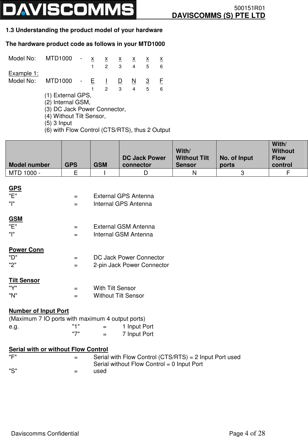
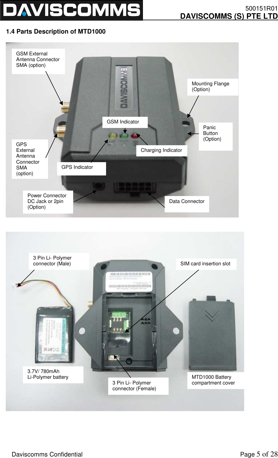
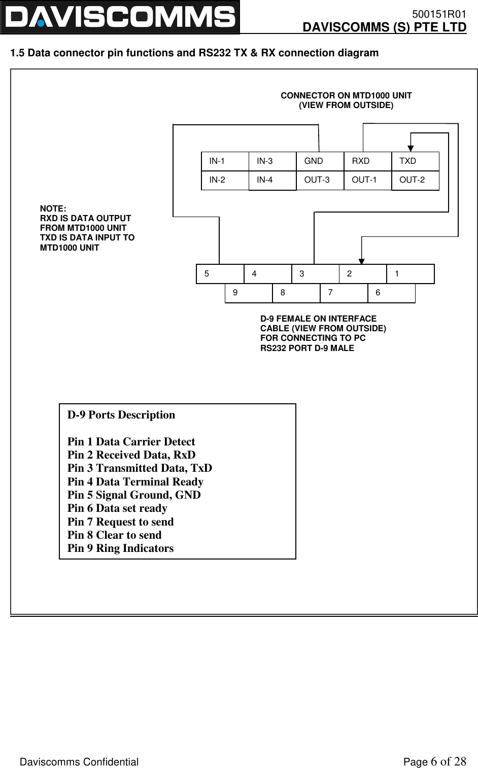
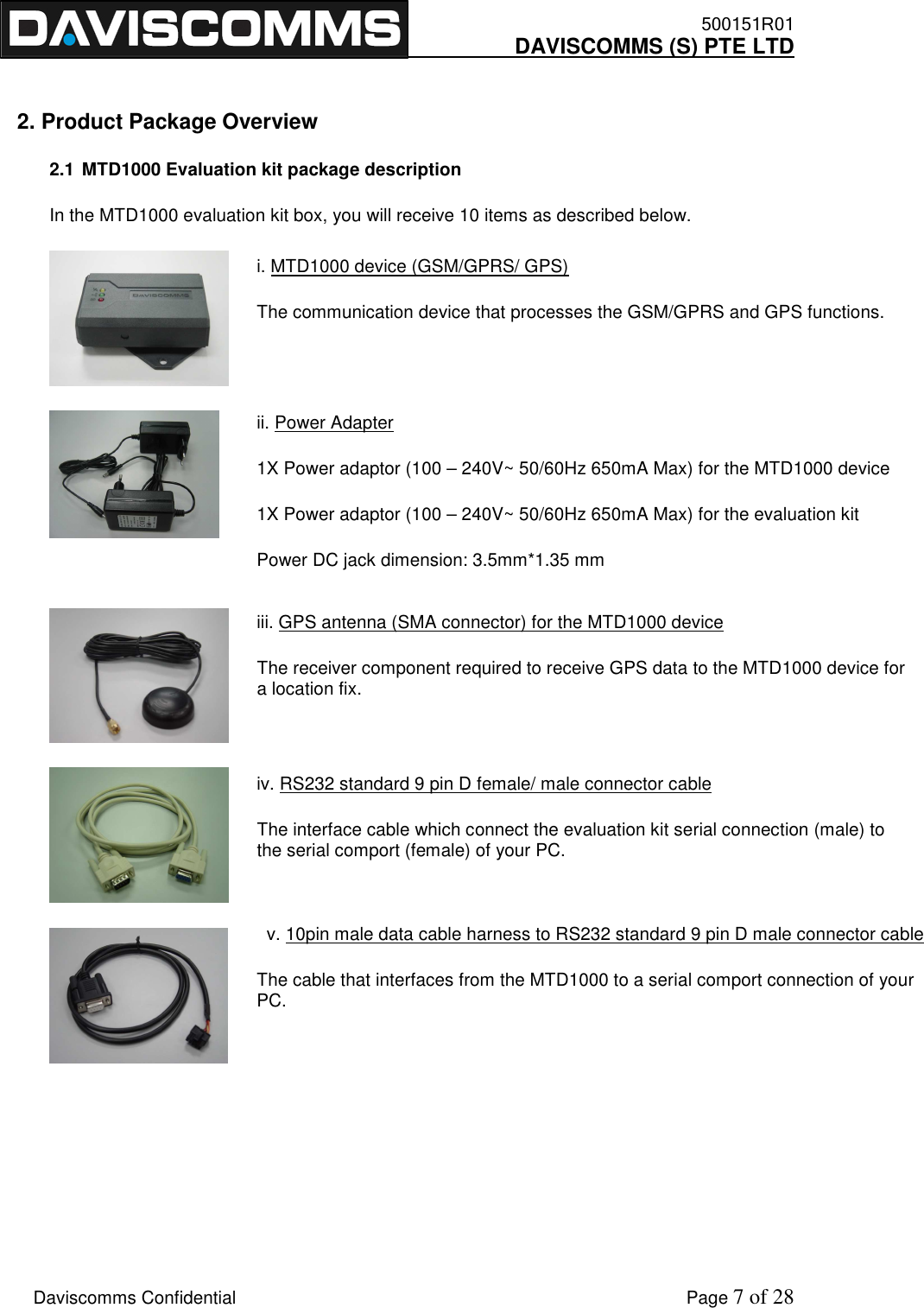
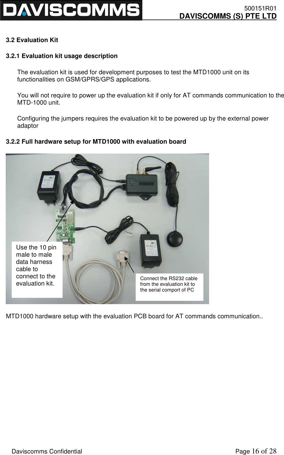
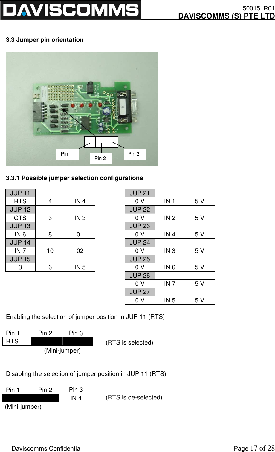
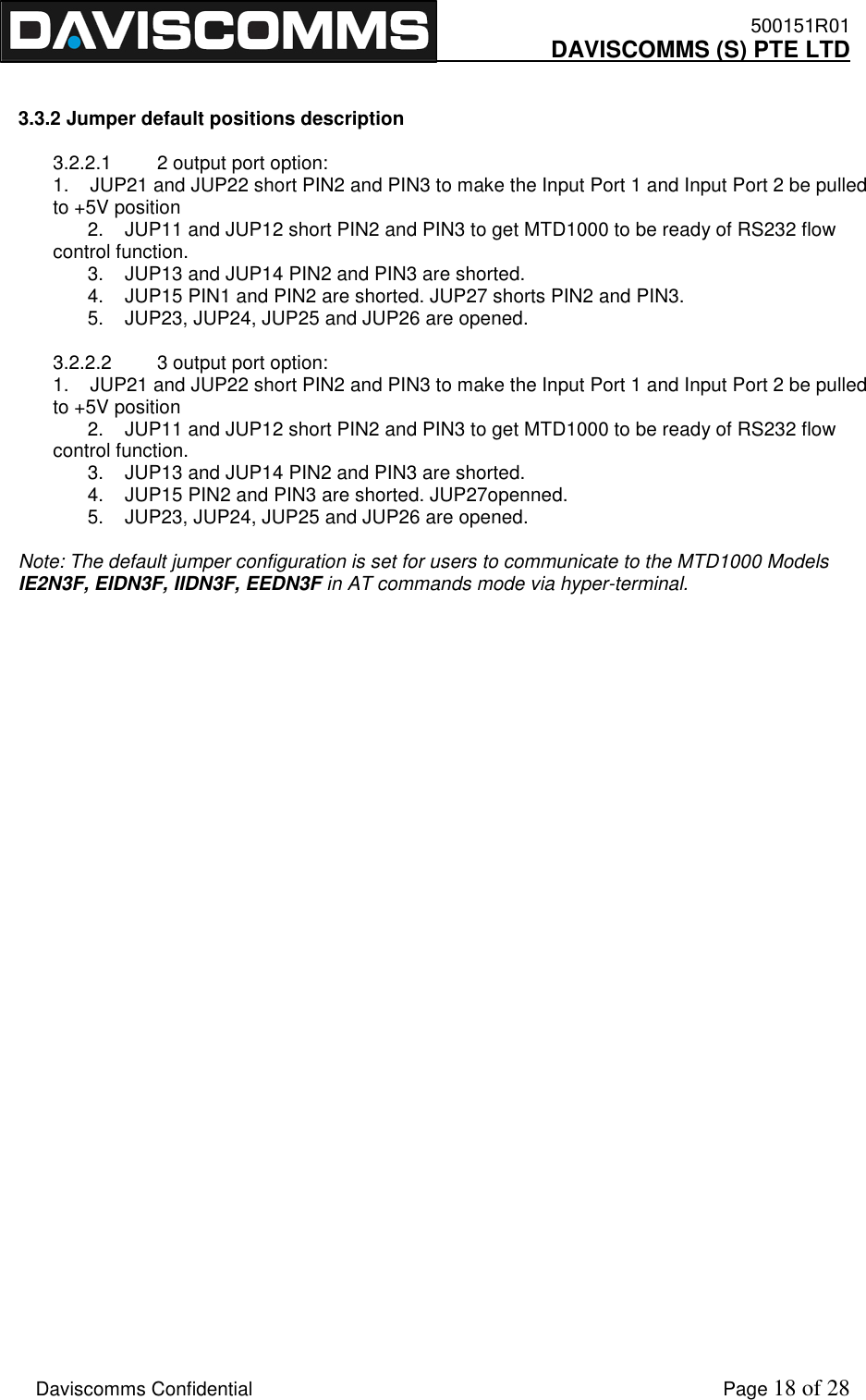
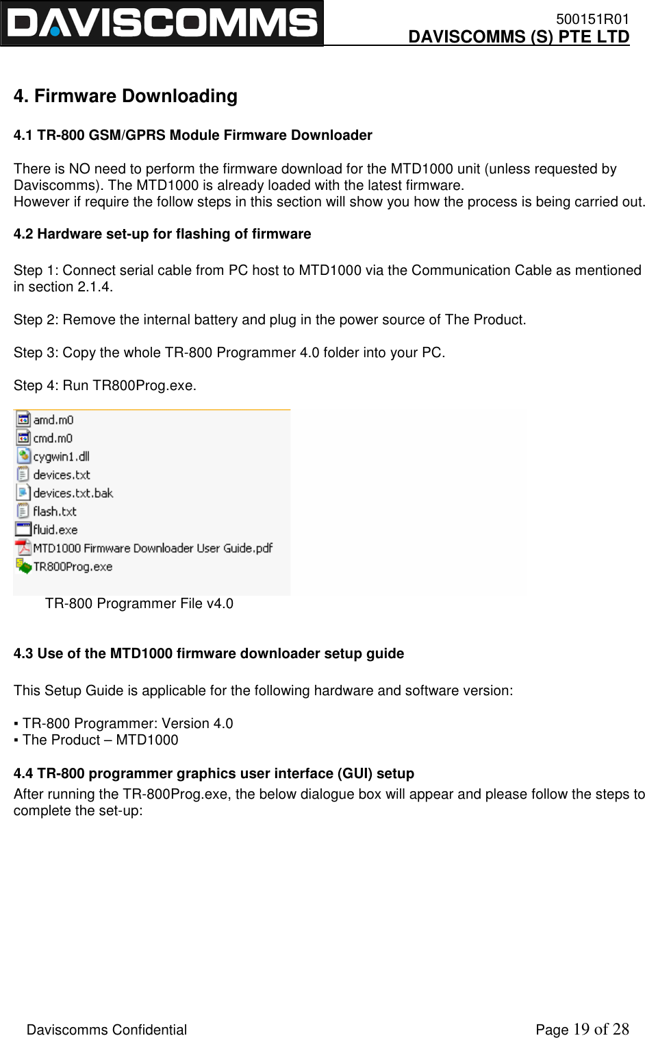
Daviscomms MTD1000 GPRS/GPS Mobile Tracking Device User Manual MTD 1000 User Guide Rev1 3

Daviscomms (S) Pte Ltd GPRS/GPS Mobile Tracking Device MTD 1000 User Guide Rev1 3

User Manual

   500151R01     DAVISCOMMS (S) PTE LTD  Daviscomms Confidential        MTD1000/Evaluation Kit User Guide
   500151R01     DAVISCOMMS (S) PTE LTD    Daviscomms Confidential    Page 1 of 28   2   3   4   5   6 Contents Preface                           Page No. 1  System Overview ----------------------------------------------------------------------------------------   2 2  Product Package Overview ---------------------------------------------------------------------------    7 3  Interfacing the MTD1000/ Evaluation kit for AT commands communication -------------   17 4  Firmware Downloading ---------------------------------------------------------------------------------  19 5  Terminology -----------------------------------------------------------------------------------------------  23 1. System Overview                      1.1 MTD1000 ---------------------------------------------------------------------------------------------------   1.2 Family of options available for MTD1000 hardware configurations--------------------------   1.3 Understanding the product code of your hardware ---------------------------------------------     1.4 Part Description of MTD1000 -------------------------------------------------------------------------    1.5 Data connector pin functions and RS232 TX & RX connection diagram ------------------    2. Product Package Overview           2.1 MTD1000 Evaluation kit package description ----------------------------------------------------   7 2.2 Installation and starting up on the MTD1000 -----------------------------------------------------   9 2.3 LED indicators description ----------------------------------------------------------------------------   12   2.3.1 Red LED (Charging Indicator) ----------------------------------------------------------  12   2.3.2 Green LED (GSM Indicator) ------------------------------------------------------------  12   2.3.3 Yellow LED (GPS Indicator) ------------------------------------------------------------  12 3. Interfacing the MTD1000/ Evaluation kit for AT commands communication 3.1 Hyper-terminal Settings -------------------------------------------------------------------------------    13 3.2 Evaluation kit ---------------------------------------------------------------------------------------------   16   3.2.1) Evaluation kit usage description ------------------------------------------------------   16              3.2.2 Full hardware setup for MTD1000 with evaluation board ----------------------  16 3.3 Jumper pin orientation --------------------------------------------------------------------------------    17 3.3.1) Possible jumper selection configurations ------------------------------------------    17     3.3.2) Jumper default positions description ------------------------------------------------  18  4. Firmware Downloading  4.1 TR-800 GSM/GPRS Module Firmware Downloader -----------------------------------------     19 4.2 Use of the MTD1000 firmware downloader setup guide ------------------------------------     19 4.3 Hardware setup for flashing of firmware --------------------------------------------------------     19 4.4 TR-800 programmer graphics user interface (GUI) setup ----------------------------------     19 5. Terminology 5.1 GSM ----------------------------------------------------------------------------------------------------  23 5.2 SIM CARD --------------------------------------------------------------------------------------------  23 5.3 GPS ----------------------------------------------------------------------------------------------------  23 5.4 GPRS --------------------------------------------------------------------------------------------------  23 5.5 SMS ----------------------------------------------------------------------------------------------------  23 5.6 Hyper-terminal ---------------------------------------------------------------------------------------  23 6. GSM antenna ---------------------------------------------------------------------------------------------  24
   500151R01     DAVISCOMMS (S) PTE LTD    Daviscomms Confidential    Page 2 of 28  1. System Overview  1.1 MTD1000  The MTD1000 is a small, economical and low cost, high quality multi-purpose GPS/ GSM tracking solution for personal and vehicle tracking. It can also be used as 2-way telemetry to control relays and transmit short messages. With battery embedded, it can remain on standby for at least 24 hours. It transmits the GPS data by using GPRS/SMS.  For efficient data management, it comes with a memory capacity of 6,000 full detail reports that include position, date, time, system and input/output ports status enabling continuous recording of position and time. The data can be downloaded either over-the-air or stored for downloading at a later time.  The MTD1000 is capable of producing it own unique device ID.  Field Applications: •  Vehicle tracking device (GSM or GSM/ GPS) •  Anti-theft (GSM or GSM/ GPS with tilt sensor or equivalent) •  Personal emergency alert with panic button •  2-way telemetry
   500151R01     DAVISCOMMS (S) PTE LTD    Daviscomms Confidential    Page 3 of 28  1.2 Family of options available for MTD1000 hardware configurations            Options available for MTD1000  •  With/ Without Panic button •  With Power connector DC jack or 2 pin power connector •  With/ Without Mounting Flange (5mm diameter hole each) •  Adaptor Chargers for Europe or USA    Model: MTD1000 - IE2N3F    -  Embedded GPS antenna. -  External GSM antenna  -  Easy in-vehicle mounting flange installation option. Model: MTD1000 - EIDN3F   -  Embedded GSM/GPRS antenna. -  External GPS antenna    Model: MTD1000 - IIDN3F  -  Embedded GSM/GPRS antenna -  Embedded GPS antenna  -  Easy in-vehicle mounting flange installation option.    Model: MTD1000 - EEDN3F -  External GSM/GPRS antenna - External GPS antenna - Easy in-vehicle mounting flange installation option.
   500151R01     DAVISCOMMS (S) PTE LTD    Daviscomms Confidential    Page 4 of 28  1.3 Understanding the product model of your hardware  The hardware product code as follows in your MTD1000  Model No:   MTD1000  -  x  x  x  x  x  x                   1  2  3  4  5  6             Example 1:                            Model No:   MTD1000  -  E  I  D  N  3  F                   1  2  3  4  5  6              (1) External GPS,  (2) Internal GSM,  (3) DC Jack Power Connector,  (4) Without Tilt Sensor,  (5) 3 Input  (6) with Flow Control (CTS/RTS), thus 2 Output  Model number  GPS  GSM  DC Jack Power connector With/ Without Tilt Sensor  No. of Input ports With/ Without Flow control MTD 1000 -  E  I  D  N  3  F              GPS             "E"   =  External GPS Antenna       "I"  =  Internal GPS Antenna                    GSM             "E"   =  External GSM Antenna       "I"  =  Internal GSM Antenna                    Power Conn             "D"  =  DC Jack Power Connector       "2"  =  2-pin Jack Power Connector                    Tilt Sensor             "Y"  =  With Tilt Sensor       "N"  =  Without Tilt Sensor                    Number of Input Port           (Maximum 7 IO ports with maximum 4 output ports)       e.g.  "1"  =  1 Input Port         "7"  =  7 Input Port                    Serial with or without Flow Control         "F"  =  Serial with Flow Control (CTS/RTS) = 2 Input Port used   "S"  =  Serial without Flow Control = 0 Input Port used
   500151R01     DAVISCOMMS (S) PTE LTD    Daviscomms Confidential    Page 5 of 28  1.4 Parts Description of MTD1000         Data Connector  Power Connector DC Jack or 2pin (Option) GPS Indicator GSM Indicator Charging Indicator GPS External Antenna Connector SMA (option) GSM External Antenna Connector SMA (option) Panic Button (Option) Mounting Flange (Option)  3.7V/ 780mAh Li-Polymer battery 3 Pin Li- Polymer connector (Male) 3 Pin Li- Polymer connector (Female) MTD1000 Battery compartment cover SIM card insertion slot
   500151R01     DAVISCOMMS (S) PTE LTD    Daviscomms Confidential    Page 6 of 28  1.5 Data connector pin functions and RS232 TX & RX connection diagram        IN-3 IN-2 IN-1 IN-4 GND OUT-3 RXD OUT-1 TXD OUT-2 CONNECTOR ON MTD1000 UNIT (VIEW FROM OUTSIDE) NOTE: RXD IS DATA OUTPUT FROM MTD1000 UNIT TXD IS DATA INPUT TO MTD1000 UNIT 2  1 6 3 7 4 8 5 9 D-9 FEMALE ON INTERFACE CABLE (VIEW FROM OUTSIDE) FOR CONNECTING TO PC RS232 PORT D-9 MALE  D-9 Ports Description  Pin 1 Data Carrier Detect Pin 2 Received Data, RxD Pin 3 Transmitted Data, TxD Pin 4 Data Terminal Ready Pin 5 Signal Ground, GND Pin 6 Data set ready Pin 7 Request to send Pin 8 Clear to send Pin 9 Ring Indicators
   500151R01     DAVISCOMMS (S) PTE LTD    Daviscomms Confidential    Page 7 of 28 i. MTD1000 device (GSM/GPRS/ GPS) The communication device that processes the GSM/GPRS and GPS functions. ii. Power Adapter 1X Power adaptor (100 – 240V~ 50/60Hz 650mA Max) for the MTD1000 device 1X Power adaptor (100 – 240V~ 50/60Hz 650mA Max) for the evaluation kit Power DC jack dimension: 3.5mm*1.35 mm iii. GPS antenna (SMA connector) for the MTD1000 device The receiver component required to receive GPS data to the MTD1000 device for a location fix. iv. RS232 standard 9 pin D female/ male connector cable The interface cable which connect the evaluation kit serial connection (male) to the serial comport (female) of your PC.   v. 10pin male data cable harness to RS232 standard 9 pin D male connector cable The cable that interfaces from the MTD1000 to a serial comport connection of your PC.   2. Product Package Overview 2.1 MTD1000 Evaluation kit package description In the MTD1000 evaluation kit box, you will receive 10 items as described below.
   500151R01     DAVISCOMMS (S) PTE LTD    Daviscomms Confidential    Page 8 of 28 vi. GSM/GPRS antenna (SMA right angle) The receiver component required to receive GSM/GPRS data to the MTD1000 device in a network cell location. vii. Li- Polymer battery for MTD1000 An alternative solution to power up the MTD1000 without a power adaptor up to 24 hours. Voltage/ current specification: (3.7V/ 780mAh)  viii. Evaluation PCB board (For development purposes on the MTD functionalities) The communications unit which allows you to configure the input and output of the MTD1000. xi. 10 pin male/male data cable harness  For connection from the evaluation board to the MTD1000 device
   500151R01     DAVISCOMMS (S) PTE LTD    Daviscomms Confidential    Page 9 of 28  2.2 Installation and starting up on the MTD1000 Step 1  -  Insert the SIM card (Not included in package) -  Connect the Li-Polymer battery to the into the MTD1000 Note: Do not use the internal Li-Ion battery beyond standard operating temperature of -10C to +50C. The MTD1000 can function directly from DC power supply adaptor without the internal Li-Ion battery. Step 2  Adjust the battery cover into the catch and slide it into the back cover latch fully.
   500151R01     DAVISCOMMS (S) PTE LTD    Daviscomms Confidential    Page 10 of 28  Step 3  Connect the GSM/GPRS antenna to the GSM External Antenna Connector. Screw in the SMA connector firmly. Step 4  Connect the GPS antenna to the GPS External Antenna Connector. Screw in the SMA connector firmly.
   500151R01     DAVISCOMMS (S) PTE LTD    Daviscomms Confidential    Page 11 of 28  Step 5          An example of the MTD1000 hardware setup with the 10 pin data harness cable/ RS232 for AT command communications and firmware flashing. (Recommended)               Connect this end to RS232 comport of PC
   500151R01     DAVISCOMMS (S) PTE LTD    Daviscomms Confidential    Page 12 of 28 2.3.1) RED LED (Charging Indicator) •  Red LED constant on:    Li-ion battery is charging •  Red LED off: Charging completed  Charge the battery by plugging in power adapter connector into the power connector of the unit. Use power adapter with similar or better ratings to prevent damage to the power adapter. If not sure, use only power adapter provided in the package.  2.3.2) GREEN LED (GSM Indicator) •  Green LED constant on: Invalid SIM Card or SIM Card not detected •  Slow  blink  (200ms  on  &  2s  off).  Device  has  found  GSM  network  & registered.  Green LED Blinking: •  Fast  blink  (200ms  on  &  600ms  off).  The  device  has  voice  or  data  line connected. 2.3.3) Yellow LED (GPS Indicator)  •  Yellow LED constant on: GPS data valid. •  Yellow LED off: GPS data invalid.  2.3 LED indicators
   500151R01     DAVISCOMMS (S) PTE LTD    Daviscomms Confidential    Page 13 of 28  3. Interfacing the MTD1000 / Evaluation kit for AT commands communication  3.1 Hyper-terminal settings  How to create a hyper-terminal connection from your PC to your device Step 1   On the Windows Start menu, select Run.... The Run dialog appears. The Windows Run Dialog  Step 2   In the Open: field, type hypertrm.exe, and click OK. The HyperTerminal splash screen appears while HyperTerminal loads. HyperTerminal Splash Screen   HyperTerminal then appears; open to the Connection Description dialog.
   500151R01     DAVISCOMMS (S) PTE LTD    Daviscomms Confidential    Page 14 of 28  Step 3   On the Connection Description screen, for Name type "Daviscomms" or any name you would prefer and select an icon for the definition, and click OK. The Connect to dialog appears. HyperTerminal Connection Description dialog  Step 4   On the Connect To dialog, select your primary COM port (COM1 e.g. the example above) for the Connect using: field, and click OK. (The Country/region:, Area code: and Phone number: fields are not used.) The COM 1 Properties dialog appears. HyperTerminal Connect To dialog
   500151R01     DAVISCOMMS (S) PTE LTD    Daviscomms Confidential    Page 15 of 28  Step 5   At the COM 1 Properties dialog, make the following selections, and then click OK: •  Bits per sec:  115200  •  Data bits:  8  •  Parity:  none  •  Stop bits:  1  •  Flow control:  none  HyperTerminal COM 1 Properties dialog   Note The settings in the Hyper Terminal need to be set correctly; otherwise, strange-looking or garbage characters may show up on the screen. If you are experiencing problems, make sure the router or modem is powered on, you are attached to the proper Com Port and verify your cabling is working. Without these correct settings, the device may display information, but does not accept any keystrokes, making it appear as if it is hung, or has crashed. If the default settings do not produce better results, your router may have been configured to use non-standard settings. To verify, try to connect at different speeds until you get a valid prompt.  Step 6   To prove you have a valid connection to a modem, type "AT" and you should receive "OK" back from the MTD1000 device. You should now be communicating with the MTD1000 device at com-port 1. Please refer to the MTD1000 Commands guide for the operation of the device.
   500151R01     DAVISCOMMS (S) PTE LTD    Daviscomms Confidential    Page 16 of 28  3.2 Evaluation Kit 3.2.1 Evaluation kit usage description The evaluation kit is used for development purposes to test the MTD1000 unit on its functionalities on GSM/GPRS/GPS applications. You will not require to power up the evaluation kit if only for AT commands communication to the MTD-1000 unit. Configuring the jumpers requires the evaluation kit to be powered up by the external power adaptor 3.2.2 Full hardware setup for MTD1000 with evaluation board  MTD1000 hardware setup with the evaluation PCB board for AT commands communication..        Connect the RS232 cable from the evaluation kit to the serial comport of PC Use the 10 pin male to male data harness cable to connect to the evaluation kit.
   500151R01     DAVISCOMMS (S) PTE LTD    Daviscomms Confidential    Page 17 of 28 (Mini-jumper) (Mini-jumper)  3.3 Jumper pin orientation  3.3.1 Possible jumper selection configurations  JUP 11        JUP 21     RTS  4  IN 4    0 V  IN 1  5 V JUP 12        JUP 22     CTS  3  IN 3    0 V  IN 2  5 V JUP 13        JUP 23     IN 6  8  01     0 V  IN 4  5 V JUP 14        JUP 24     IN 7  10  02     0 V  IN 3  5 V JUP 15        JUP 25     3  6  IN 5     0 V  IN 6  5 V         JUP 26             0 V  IN 7  5 V         JUP 27             0 V  IN 5  5 V Enabling the selection of jumper position in JUP 11 (RTS): Pin 1  Pin 2  Pin 3 RTS      Disabling the selection of jumper position in JUP 11 (RTS) Pin 1  Pin 2  Pin 3   IN 4    Pin 1  Pin 2  Pin 3 (RTS is selected) (RTS is de-selected)
   500151R01     DAVISCOMMS (S) PTE LTD    Daviscomms Confidential    Page 18 of 28   3.3.2 Jumper default positions description  3.2.2.1  2 output port option: 1.    JUP21 and JUP22 short PIN2 and PIN3 to make the Input Port 1 and Input Port 2 be pulled to +5V position    2.    JUP11 and JUP12 short PIN2 and PIN3 to get MTD1000 to be ready of RS232 flow control function.    3.    JUP13 and JUP14 PIN2 and PIN3 are shorted.    4.    JUP15 PIN1 and PIN2 are shorted. JUP27 shorts PIN2 and PIN3.    5.    JUP23, JUP24, JUP25 and JUP26 are opened.   3.2.2.2  3 output port option: 1.    JUP21 and JUP22 short PIN2 and PIN3 to make the Input Port 1 and Input Port 2 be pulled to +5V position    2.    JUP11 and JUP12 short PIN2 and PIN3 to get MTD1000 to be ready of RS232 flow control function.    3.    JUP13 and JUP14 PIN2 and PIN3 are shorted.    4.    JUP15 PIN2 and PIN3 are shorted. JUP27openned.    5.    JUP23, JUP24, JUP25 and JUP26 are opened.   Note: The default jumper configuration is set for users to communicate to the MTD1000 Models IE2N3F, EIDN3F, IIDN3F, EEDN3F in AT commands mode via hyper-terminal.
   500151R01     DAVISCOMMS (S) PTE LTD    Daviscomms Confidential    Page 19 of 28  4. Firmware Downloading  4.1 TR-800 GSM/GPRS Module Firmware Downloader   There is NO need to perform the firmware download for the MTD1000 unit (unless requested by Daviscomms). The MTD1000 is already loaded with the latest firmware. However if require the follow steps in this section will show you how the process is being carried out.  4.2 Hardware set-up for flashing of firmware  Step 1: Connect serial cable from PC host to MTD1000 via the Communication Cable as mentioned in section 2.1.4.  Step 2: Remove the internal battery and plug in the power source of The Product.   Step 3: Copy the whole TR-800 Programmer 4.0 folder into your PC.  Step 4: Run TR800Prog.exe.           TR-800 Programmer File v4.0  4.3 Use of the MTD1000 firmware downloader setup guide  This Setup Guide is applicable for the following hardware and software version:  ▪ TR-800 Programmer: Version 4.0 ▪ The Product – MTD1000 4.4 TR-800 programmer graphics user interface (GUI) setup After running the TR-800Prog.exe, the below dialogue box will appear and please follow the steps to complete the set-up:
   500151R01     DAVISCOMMS (S) PTE LTD    Daviscomms Confidential    Page 20 of 28                             TR-800 PROGRAMMER  Step 1: Enter your COM Port number. The default value is 1. The programmer will set the COM port to the following settings:   COM Port Baud Rate = 115200 bps Data Bits = 8 Parity = None Stop Bit = 1 Flow Control = None  Step 2: Browse for the m0 file (firmware file) to be programmed into the module. Ensure that the path and file name of the m0 file is correct before proceeding.                     Key in COM port number
   500151R01     DAVISCOMMS (S) PTE LTD    Daviscomms Confidential    Page 21 of 28     Step 3: Click the “Download Target File” button to begin programming.  Step 4: A new console window will be displayed as below:    Step 5: Totally power off the Product and re-Power it up.        Browser firmware file Click to begin programming
   500151R01     DAVISCOMMS (S) PTE LTD    Daviscomms Confidential    Page 22 of 28    Step 6: The flashing process will run automatically. Wait for the process to be completed.    Note: Do not remove the module, power off the Product or close the TR-800 Programmer software during this period. Doing so might cause unforeseen damage to the module.  Step 7: If the downloading is successful, a "Downloading Completed" window will be displayed as follow:    If the downloading is not successful, a "Fail. Please Try Again" window will be displayed. In case the downloading fails, repeat the set-up procedure from step 1.
   500151R01     DAVISCOMMS (S) PTE LTD    Daviscomms Confidential    Page 23 of 28  5. Terminology  5.1 GSM   Global System for Mobile Communications. A digital cellular phone technology based on TDMA that is the predominant system in worldwide.  5.2 SIM CARD Subscriber Identity Module (SIM) smart card that contains user account information  5.3 GPS Global Positioning System, a worldwide MEO satellite navigational system formed by 24 satellites orbiting the earth and their corresponding receivers on the earth  5.4 GPRS General Packet Radio Services (GPRS) is a packet-based wireless communication service that promises data rates from 56 up to 114 Kbps and continuous connection to the Internet for mobile phone and computer users. The higher data rates allow users to take part in video conferences and interact with multimedia Web sites and similar applications using mobile handheld  5.5 SMS Short Messaging System, service for sending short text messages to mobile phones  5.6 Hyper-terminal  Hyper-terminal is a terminal emulation program that comes standard with every PC running Windows 95/98, Windows 2000 or NT. Hyper-terminal allows you to configure the MTD1000 unit through the serial port on the PC.
   500151R01     DAVISCOMMS (S) PTE LTD    Daviscomms Confidential    Page 24 of 28  6. GSM Antenna  GSM/GPRS/AMPS ANTENNA FOR AUTOMOBILE SPECIFICATION    Vertical pattern  Electrical Specification  Mechanical Specification Product type  GSM/ GPRS/AMPRS antenna  Product type  Right SMA or RP-SMA Model Type  BH015  Model Type  BH015 Frequency Range  800/1900/900/1800Mhz  Height  46.5mm Impedance  50 ohms  Max diameter  9.0mm VSWR  1:1:5  Min Diameter  6.0mm Gain (Typical)  2.15db  Connector  SMA RA Gain (Max)  2.5db  Lightning protection  Yes Polarization  Vertical Radiation  0mni Max Power  20V Maximum Input Power  50w
   500151R01     DAVISCOMMS (S) PTE LTD    Daviscomms Confidential    Page 25 of 28           Vertical pattern at 960Mhz
   500151R01     DAVISCOMMS (S) PTE LTD    Daviscomms Confidential    Page 26 of 28       Impedance circle diagram((((Smith circle diagram
   500151R01     DAVISCOMMS (S) PTE LTD    Daviscomms Confidential    Page 27 of 28           Usage: Connecting the SMA connector which is at the end of the antenna with the equipment directly.
   500151R01     DAVISCOMMS (S) PTE LTD    Daviscomms Confidential    Page 28 of 28   Regulatory and Warning Information  Radio Frequency Interface Requirements  Tested To Comply With FCC Standards  Note: This equipment has been tested and found to comply with Part 15 of the FCC rules. Operation is subject to the condition that this device does not cause harmful interference. This equipment generates, uses, and can radiate radio frequency energy and, if not installed and used in accordance with the user’s guide, may cause harmful interference to radio communications. There is no guarantee that interference will not occur in a particular installation. If this equipment does cause harmful interference to any electronic devices, the user is encouraged to consult the dealer for help.  This equipment complies with part 15 of the FCC Rules. Operation is subject to the following two conditions: (1) this equipment may not cause harmful interference, and (2) this equipment must accept any interference received, including interference that may cause undesired operation. Any changes or modifications made without the approval by the party responsible for compliance could void the user’s authority to operate this equipment.  Note: The manufacturer is not responsible for any interference caused by unauthorized modifications made by the user to this equipment. Such modifications could void the user’s authority to operate the equipment.      The antenna(s) used for this transmitter must be installed to provide a separation distance of at least 20 cm from all persons and must not be co-located or operating in conjunction with any other antenna or transmitter.  RF Exposure Guidelines

Navigation menu