Decatur Electronics SI-3L Low profile directional radar unit User Manual
Decatur Electronics Inc Low profile directional radar unit Users Manual
UserManual.wiki
>
Decatur Electronics
>
SI 3L User Manual
Users Manual
Navigation menu
Upload a User Manual
Namespaces
Wiki Guide
HTML
PDF
Info
Views
User Manual
Discussion / Help
Navigation

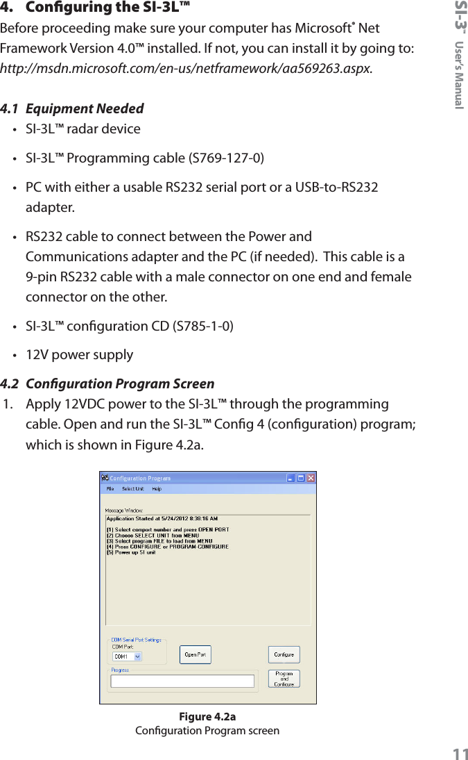
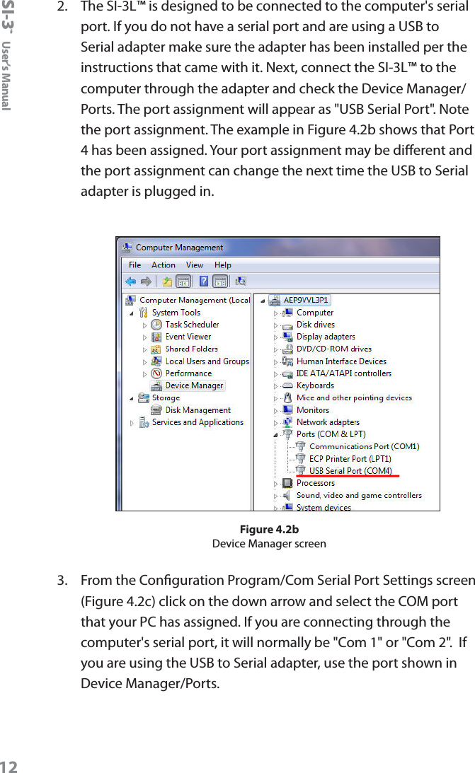
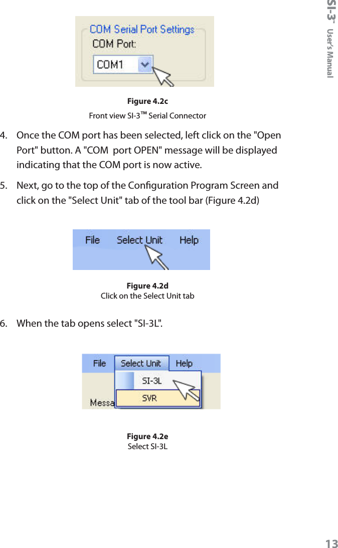
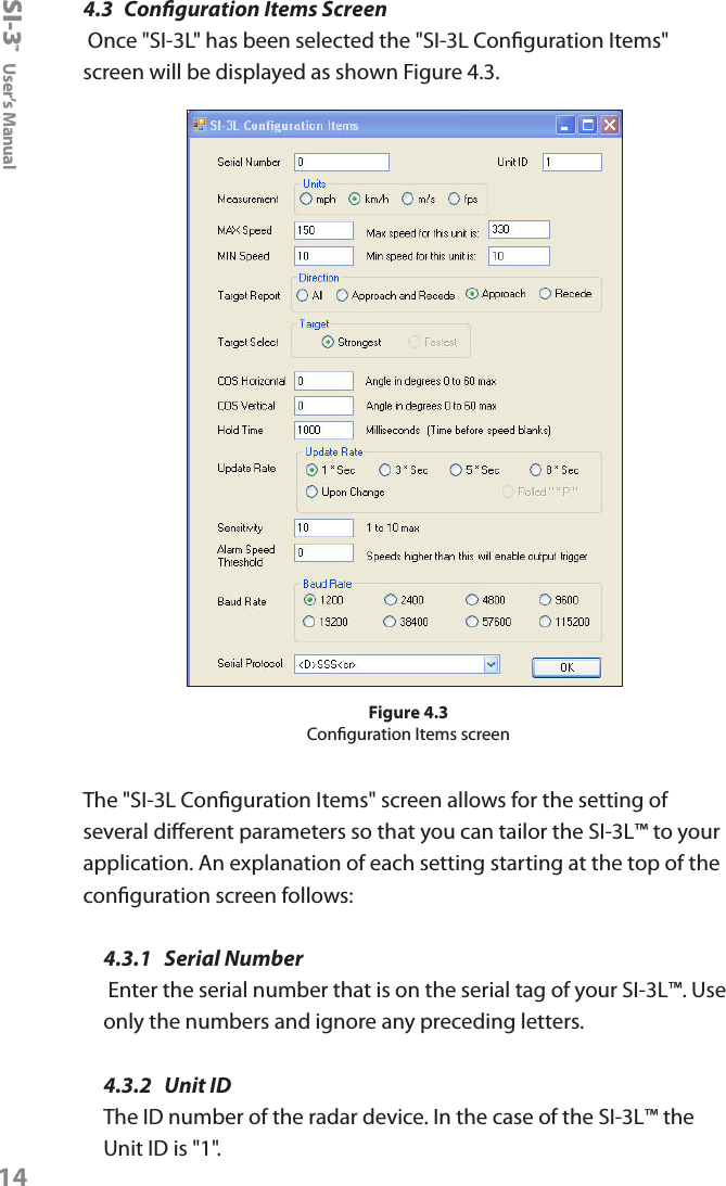
![SI-3™ User’s Manual204.3.12 Serial ProtocolCurrently there is only one protocol available. <D> is a direction character that is “+” for vehicles coming towards the sign, “-“ for vehicles moving away, and “?” when the direction cannot be determined. [S] represents the displayed speed. If a period is within the square brackets it is the decimal point. Any zeros are sent as described and do not change with a vehicle’s speed. The <cr> signies the end of the outgoing message. Figure 4.3.12Serial Protocol4.4 Select Program FILE to Load from MENU (Optional)From time to time Decatur Electronics will release new rmware for the SI-3L™ . If you have received new rmware then save the rmware to a le on your hard drive remembering the path to where the le is saved. If you have new rmware and need to congure the rmware to the SI-3L™ then click on the "File" tab at the top of the screen.Figure 4.4Click on the "File" tab From "File" go to where you have saved the new rmware and click on the le. Next, proceed to Section 4.5. 4.5 Press CONFIGURE or PROGRAM-CONFIGURETwo options are available. You can either congure the SI-3L™ to only accept the changes you have made to the "SI-3L Conguration Items" screen (Figure 4.3a) or you can congure the SI-3L™ to accept the changes you have made to the "SI-3L Conguration Items screen" and to also accept the new rmware.](https://usermanual.wiki/Decatur-Electronics/SI-3L/User-Guide-1908393-Page-20.png)