Digianswer A S BTDVK110 Bluetooth Developer Kit User Manual dev userguide
Digianswer A/S Bluetooth Developer Kit dev userguide
UserManual.wiki
>
Digianswer A S
>
BTDVK110 User Manual
Users Manual
Navigation menu
Upload a User Manual
Namespaces
Wiki Guide
HTML
PDF
Info
Views
User Manual
Discussion / Help
Navigation
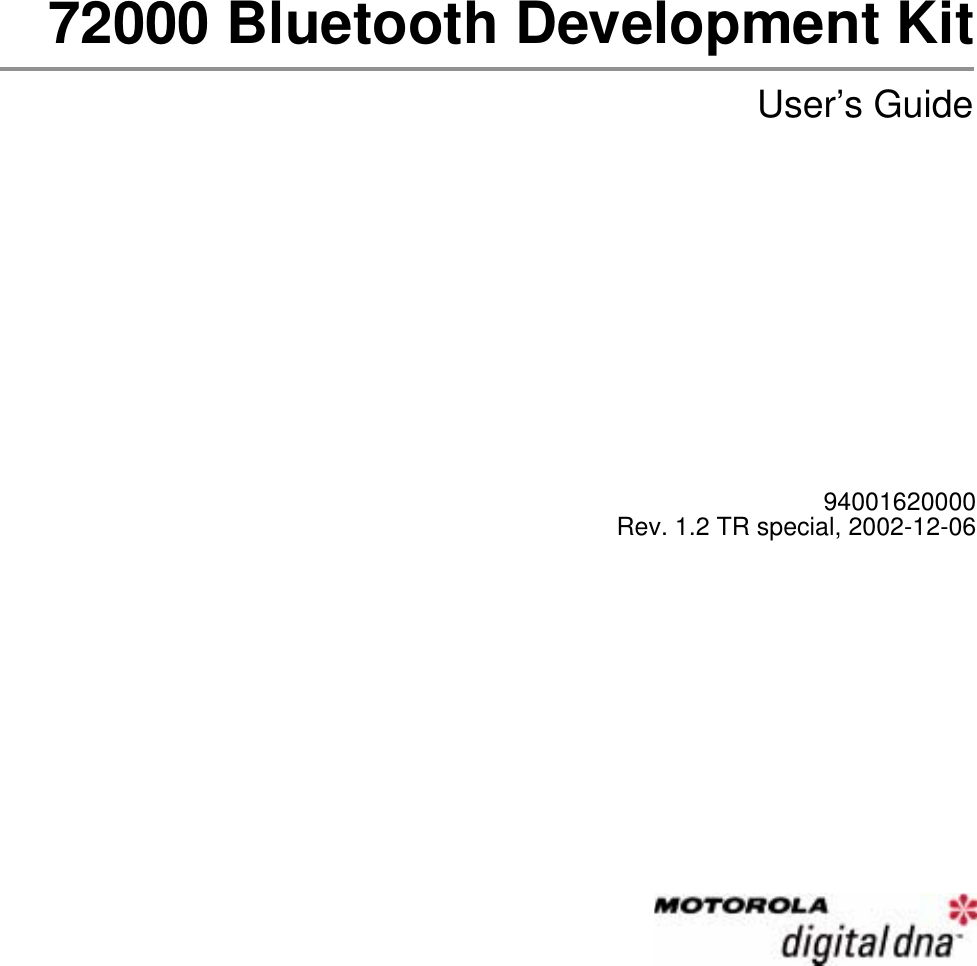


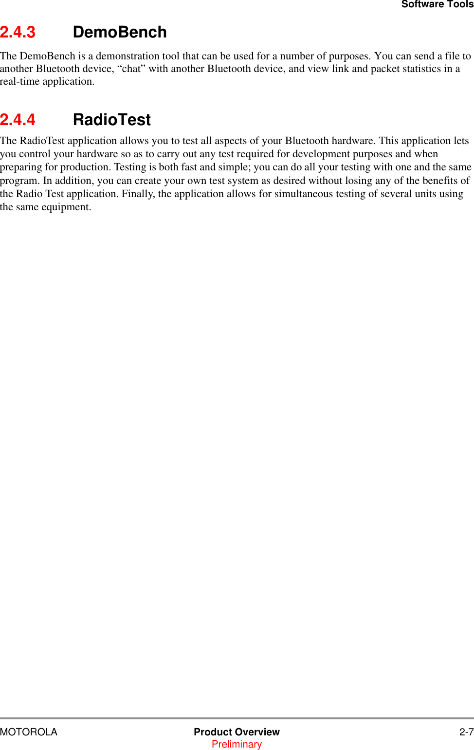


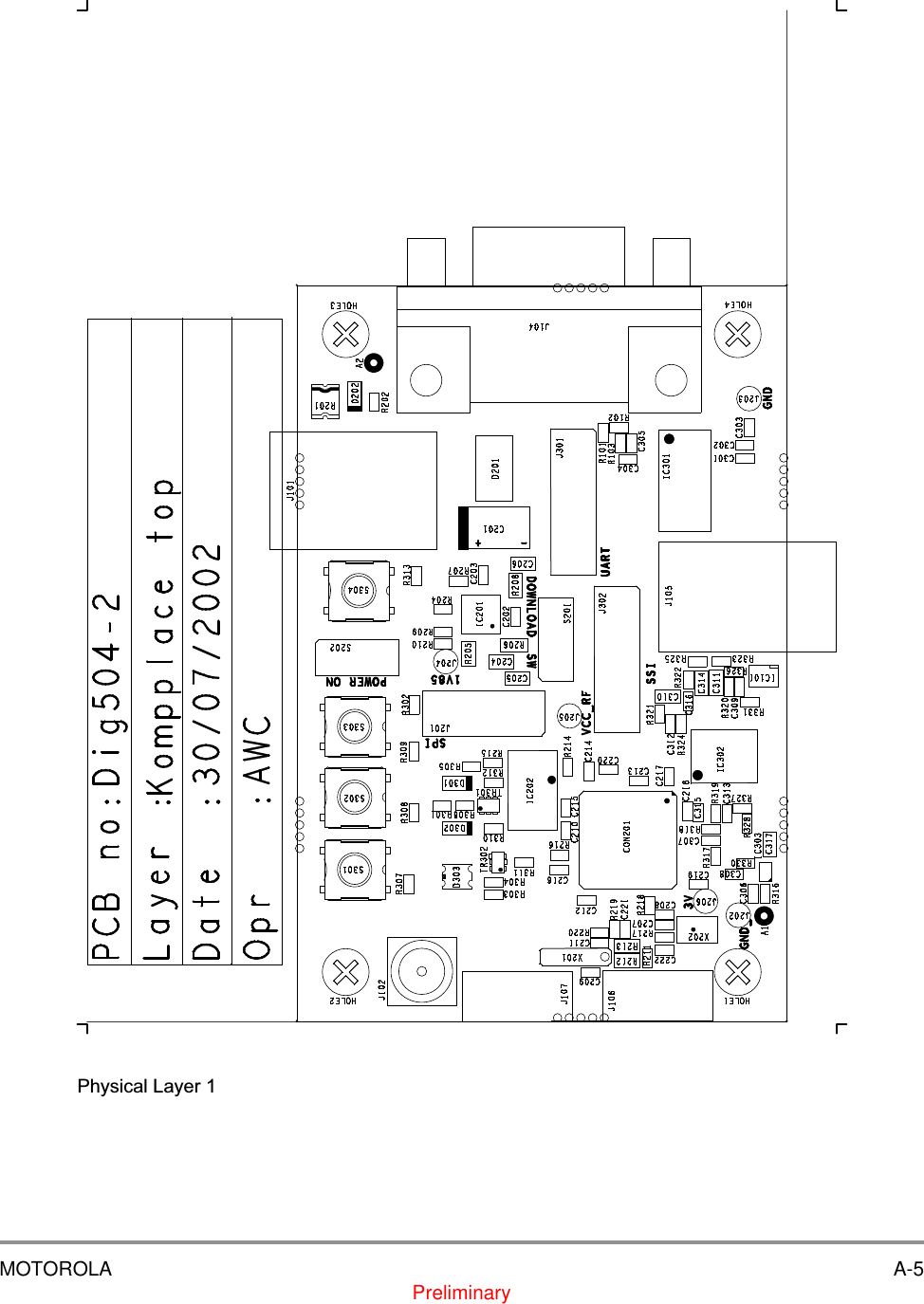
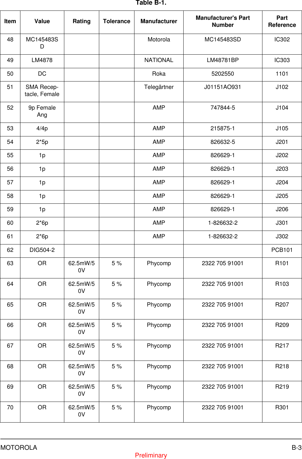
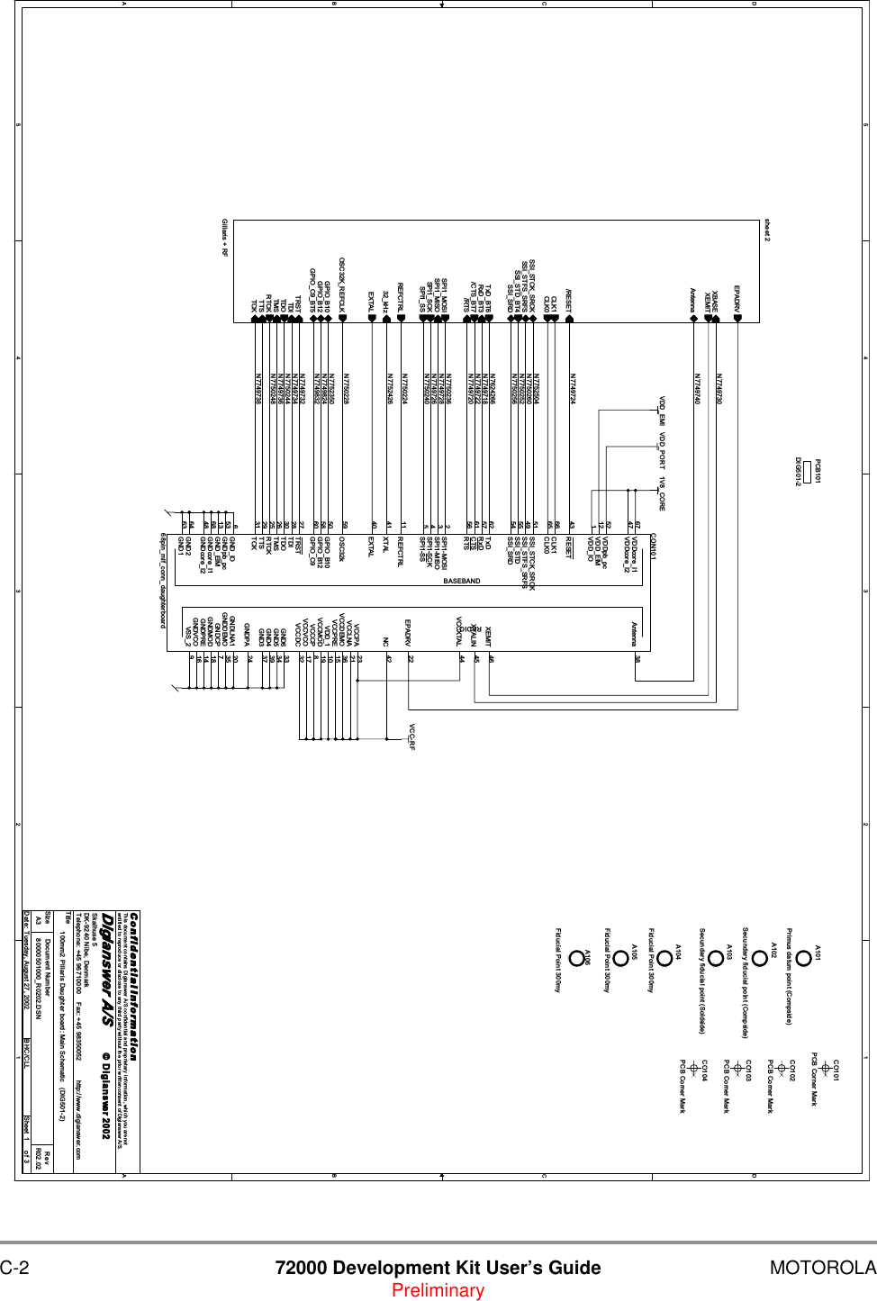
![A-2 72000 Development Kit User’s Guide MOTOROLAPreliminary5544332211D DC CB BA AMAIN+RTSTXDRXDCTSMIC-RFNET2EAR-EAR+MIC+UART[0..3]RESETSSI[0..3]GPIO[0..3]JTAG[0..6]JTAG0JTAG3JTAG4 JTAG2JTAG6JTAG1VDD1V85TitleSize Document Number RevDate: Sheet ofC o n f i d e n t i a l I n fo r ma t i o nThis document contains Digianswer A/S confidential and proprietary information, which you are notentitled to reproduce or disclose to any third party without the prior written consent of Digianswer A/S.© Digianswer80000504000_R0200.DSN R02.00MC72000 Development kit (DIG504-2) : Main schematicDigianswer A/SSkalhuse 5DK-9240 Nibe, DenmarkTelephone: +45 96710000 Fax: +45 98350052 http://www.digianswer.comA314Thursday, August 01, 2002 CLL20024- 6VDCPower SupplyUAR TANT E NNAJTAG13M H z oscillat or32k H z oscillat orJ107Not Mounted12534CO3PCB Corner MarkJ106Not Mounted12534R101 0RJ101DC3214A1Primus datum point (Compside)HOLE1np hole ø4.2mmJ1049p Female Ang594837261m1 m2Sheet3Module PeripheralsREFCTRLTXDCTSRTSRXDUART[0..3] BT_WAKEUPRiSSI[0..3]Speak+Speak-MIC+MIC-GPIO[0..3]CLK0CLK1EPADRVRESETPower_ONA2Secundary fiducial point (Compside)HOLE2np hole ø4.2mmJ102SMA Receptacle, Female12534CO4PCB Corner MarkIC101MMQA5V6T1C1 6A15C2 4C3 3A22C4 1R1020RNot MountedA3Secundary fiducial point (Soldside)HOLE3np hole ø4.2mmCO2PCB Corner MarkJ1054/4p11223344PCB101DIG504-2HOLE4np hole ø4.2mmJ103Not Mounted1 23 45 67 8109CO1PCB Corner MarkR103 0RSheet 2Module and PowerMAIN+UART[0..3]SSI[0..3]JTAG[0..6] AntennaGPIO[0..3]CLK0CLK1EPADRVREFCTRLRESETPower_ON 13MHz_osc32kHz_osc](https://usermanual.wiki/Digianswer-A-S/BTDVK110/User-Guide-288553-Page-28.png)
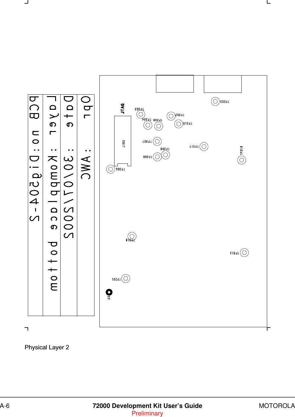
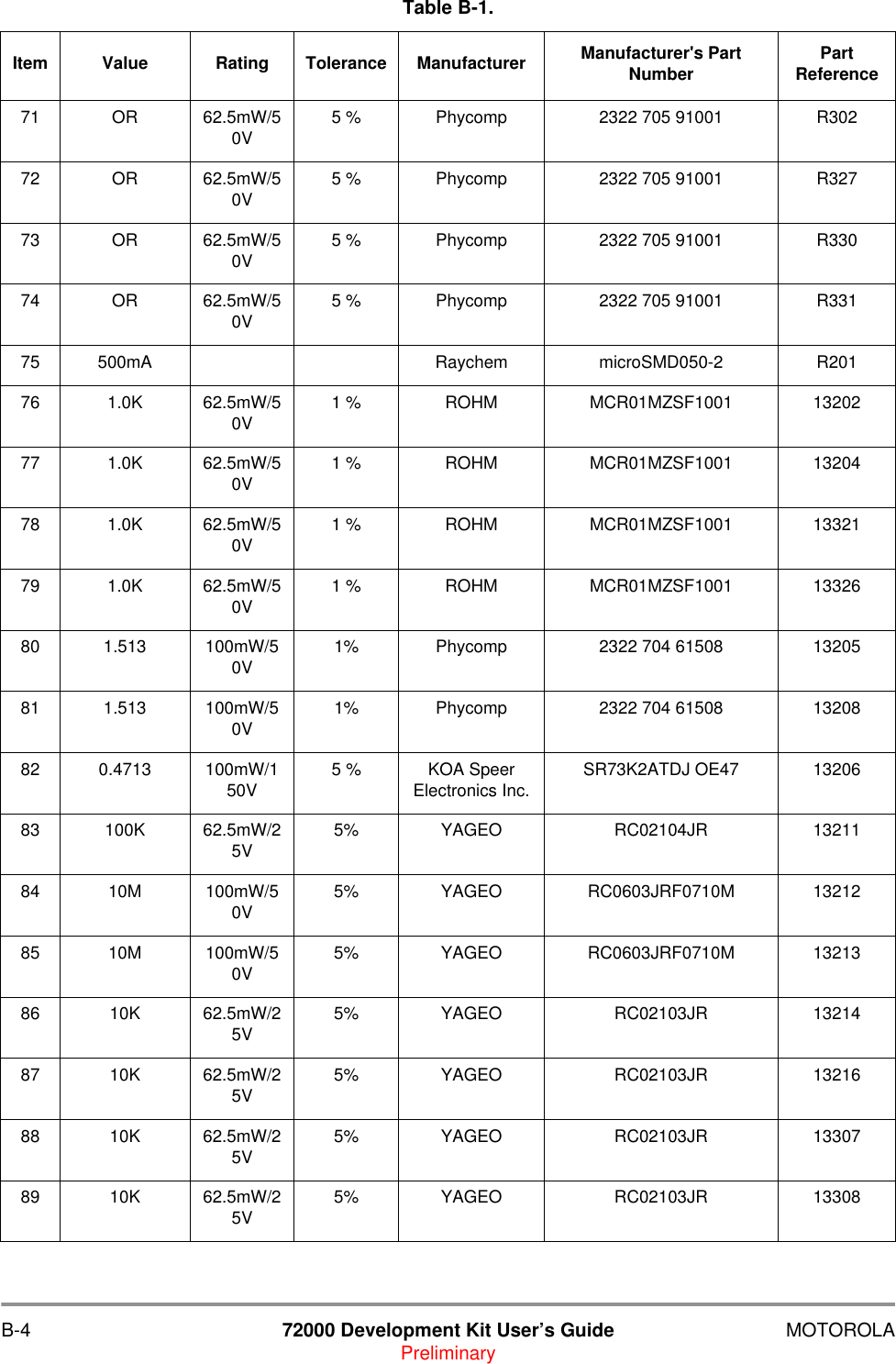
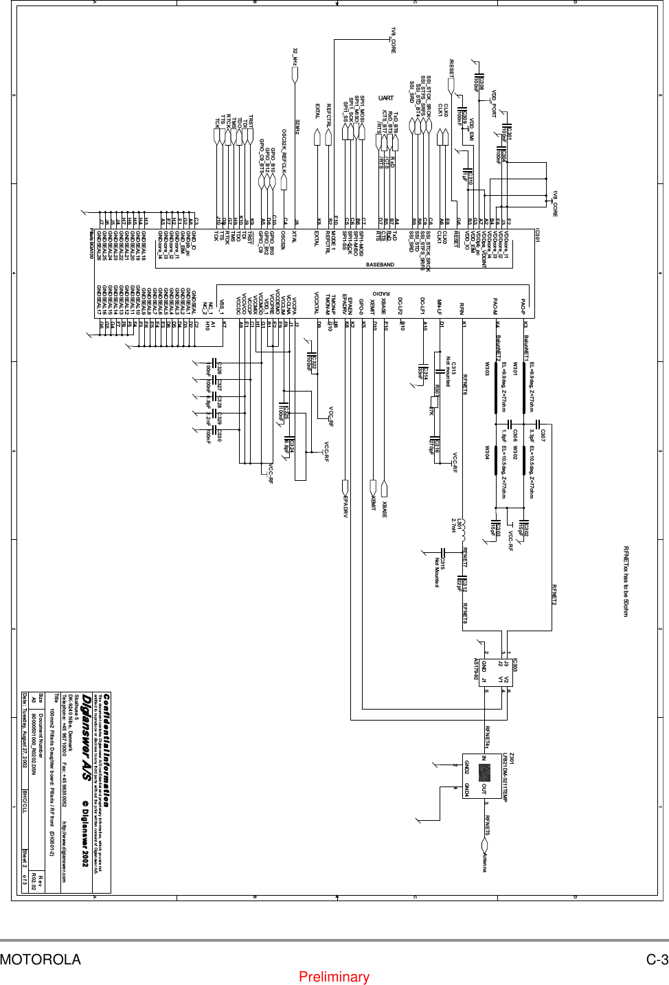
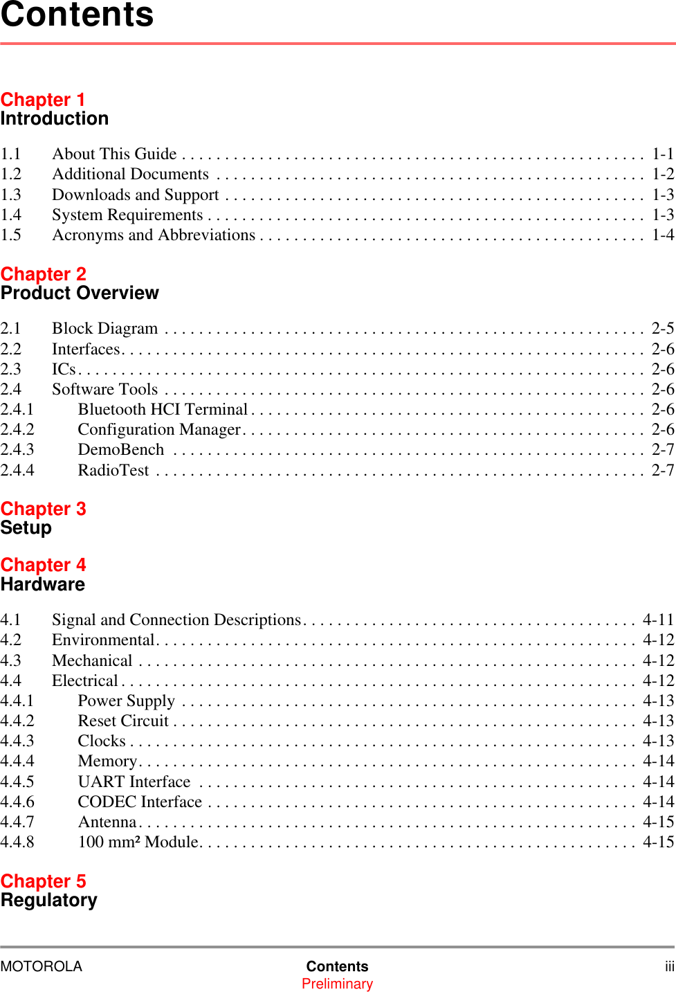
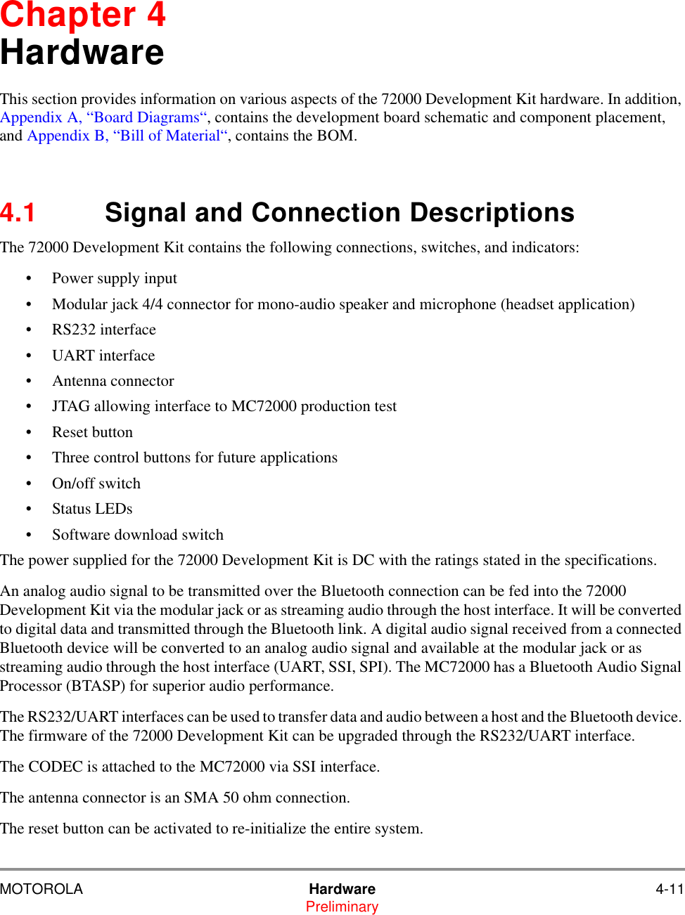
![MOTOROLA A-3Preliminary5544332211D DC CB BA ASPI13SPI12SPI11SPI10UART1UART2UART0UART3SSI0SSI1SSI2SSI3JTAG0JTAG1JTAG2JTAG3JTAG4JTAG6GPIO0GPIO1GPIO2RFNET1RESETGPIO3JTAG5SPI11SPI10SPI12SPI13MAIN+UART[0..3]SSI[0..3]JTAG[0..6]AntennaGPIO[0..3]EPADRVREFCTRLRESETCLK0CLK113MHz_osc32kHz_oscVCCVCC_RFVDD1V85VDD3VVCCVDD1V85VDD3VVCC_RFVDD3VVCC_RFVDD1V85 VCC_RF VDD3VTitleSize Document Number RevDate: Sheet ofC o n f i d e n t i a l I n fo r ma t i o nThis document contains Digianswer A/S confidential and proprietary information, which you are notentitled to reproduce or disclose to any third party without the prior written consent of Digianswer A/S.© Digianswer80000504000_R0200.DSN R02.00MC72000 Development kit (DIG504-2) : Module and PowerDigianswer A/SSkalhuse 5DK-9240 Nibe, DenmarkTelephone: +45 96710000 Fax: +45 98350052 http://www.digianswer.comA324Thursday, August 01, 2002 CLL2002Z0=50ohm Track 523µm, layer 1-2 300µmC2041µFJ2012*5p1 23 45 67 8109IC202AT25HP512-10CI-1.8 CS 1SO 2WP3GND4SI 5SCK 6HOLD7VCC8C219100nFR2081.5RR21310MR2021.0KR2180RR2090RC214100nFC215100nFX20213.000MHzD201BZV90C6V83241J2031pIC201MC13181VCC13Vin+24Vin-23HysteresisSelect21DelayCap 9Q1_b10 S INV6Q211S OR122V65_ENABLE17 1V85_ENABLE183V0/3V3 sel143V0/3V3 ENABLE13AGND1 4OUT3V0/3V3 7OUT2V65 1OUT1V85 19RESET_b 15Detect 22REFOUT 2VCC28Shutdown16AGND2 20SGND 5EP EPR215470RR204 1.0KX20132.768KHzTP201R2060.47RC201100µFR2190RR2070RTP205C222Not MountedC216100nFR21610KR201500mA1 2J2021pC20815pFC220100nFR217 0RBASEBANDRADIOFor DIG499-2 and DIG501-2CON201100mm2 Pillaris Daughter boardRESET43SSI_STCK_SRCK51SSI_STFS_SRFS49SSI_STD55SSI_SRD54TxD62RxD57CTS61RTS56SPI1-MOSI2SPI1-MISO3SPI1-SCK4SPI1-SS5GPIO_C960XBASE 45XEMIT 46OSC32k59GPIO_B1050GPIO_B1258GND264GND163Antenna 38XTAL41 NC 42EXTAL40GND3 37GND6 33EPADRV 22GND5 34GND4 39GNDPA 24GNDDEMO 35GNDLNA1 20GNDCP 7GNDMOD 18GNDPRE 14GNDVCO 16REFCTRL11TRST27TDI28TDO30TMS26RTCK25TTS29TCK31VSS_2 9CLK065GND_IO6GNDpb_pc53GND_EIM13GNDcore_I168GNDcore_I248VDDcore_I167VDDcore_I247VCCXTAL 44CLK166VDDpb_pc52VDD_EIM12VDD_IO1VCCPA 23VCCLNA 21VCCDEMO 36VCCPRE 15VDD_1 10VCCMOD 19VCCCP 8VCCVCO 17VCCDC 32C2051µFR21410KR211100KD202Green LEDJ2061pR2051.5RC210100nFC21110pFC212100nFC217100nFR21210MC20715pFC218100nFJ2051pS202Switch123C2061µFC203100nFR210Not MountedC202100nFR220Not MountedC213100nFC20910pFC221Not MountedS201Switch123J2041p](https://usermanual.wiki/Digianswer-A-S/BTDVK110/User-Guide-288553-Page-29.png)
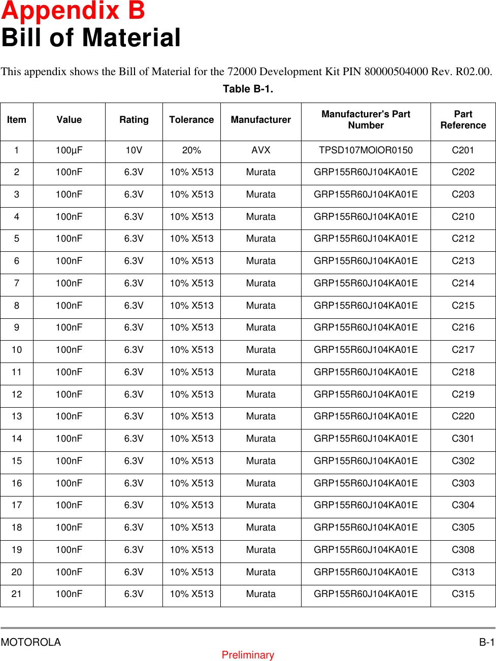
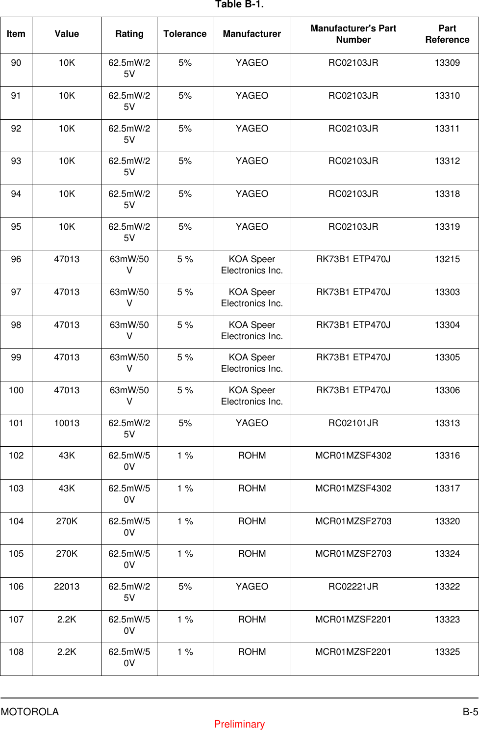
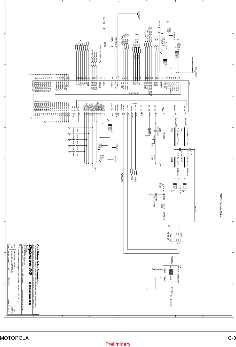
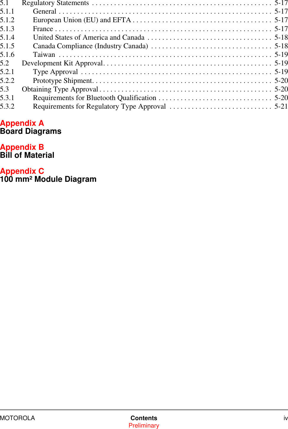
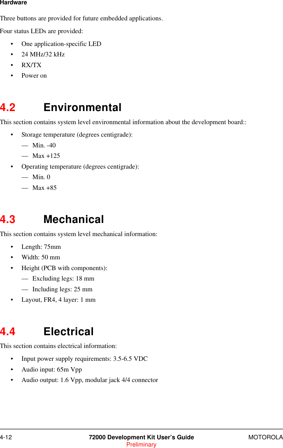
![A-4 72000 Development Kit User’s Guide MOTOROLAPreliminary5544332211D DC CB BA AGPIO1GPIO2GPIO0UART3UART2UART0UART1UART[0..3]SSI0SSI1SSI2SSI3GPIO3SSI[0..3]GPIO[0..3]CLK1REFCTRLEPADRVTXDCTSRTSRXDSpeak+Speak-UART[0..3]BT_WAKEUPRiMIC+MIC-CLK0RESETGPIO[0..3]VAGVDD3VVAGVCCVDD3VVDD3VVDD3VVDD3VTitleSize Document Number RevDate: Sheet ofC o n f i d e n t i a l I n fo r ma t i o nThis document contains Digianswer A/S confidential and proprietary information, which you are notentitled to reproduce or disclose to any third party without the prior written consent of Digianswer A/S.© Digianswer80000504000_R0200.DSN R02.00MC72000 Development kit (DIG504-2) : Module peripheralsDigianswer A/SSkalhuse 5DK-9240 Nibe, DenmarkTelephone: +45 96710000 Fax: +45 98350052 http://www.digianswer.comA334Thursday, August 01, 2002 CLL2002Keys24MHz / 32kHzLevel shifterVol +Vol - BTR320270KR3010RJ3022*6p1 23 45 67 891011 12C313100nFTR301ABC847BS261C301100nFR3252.2KR303470RC316100nFTP317R30710KR305470RTP304C303100nFR313100RS303SPSTR324270KC314330nFR31810KC3171µFS301SPSTTP309R306470RTP316R31210KC305100nFR3270RGRD303Red/Green LED SMD14 32R30810KTR301BBC847BS534TP318C312150pFTP305C30722nFIC302MC145483SDVAG-Ref 1RO- 2PI 3PO- 4PO+ 5VDD6FSR7DR8BCLKR9PDI10DT13FST14VSS15HB16 TG 17TI- 18TI+ 19VAG 20BCLKT12MCLK11D302Green LEDTR302ABC847BS261R3261.0KR31743KR3310RC302100nFR30910KR304470RC309150pFTP307R31110KTP302C3101µFC3061.0nFR31643KJ3012*6p1 23 45 67 891011 12R3020RR328Not MountedIC303LM4878-IN1+IN7Bypass3Shutdown5VDD 6OUT 1 8OUT 2 4GND 2TP306TP315R322220RS302SPSTR3300RTP310C315100nFC308100nFC304100nFS304SPSTR3211.0KIC301MAX3237EAIC1+28C1-25C2+1C2-3T1IN24T2IN23R1OUT21R2OUT20VCC 26V+ 27V- 4GND 2T1OUT 5T2OUT 6R1IN 8R2IN 9T3IN22T4IN19T5IN17T3OUT 7T4OUT 10T5OUT 12R1OUTB16R3OUT18 R3IN 11MBAUD 15SHDN 14EN13C311330nFR31910KD301Red LEDR3232.2KTP303R31010KTP308](https://usermanual.wiki/Digianswer-A-S/BTDVK110/User-Guide-288553-Page-30.png)