ELCON Systemtechnik 6600 E-TRIP ® 6600 User Manual OPERATING MANUAL E TRIP 9502
ELCON Systemtechnik GmbH E-TRIP ® 6600 OPERATING MANUAL E TRIP 9502
UserManual.wiki
>
ELCON Systemtechnik
>
6600 User Manual
>
Operating Manual
Contents
1.
Mounting Manual
2.
Operating Manual
Operating Manual
Navigation menu
Upload a User Manual
Namespaces
Wiki Guide
HTML
PDF
Info
Views
User Manual
Discussion / Help
Navigation
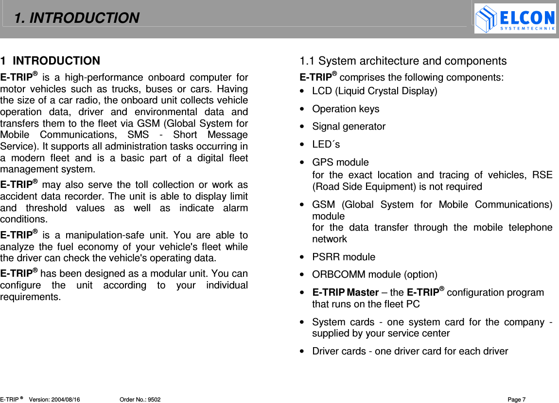
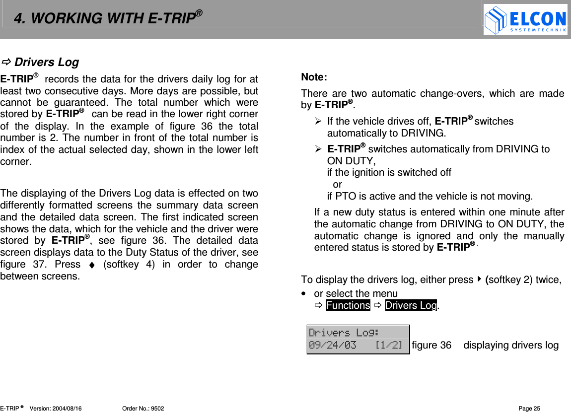
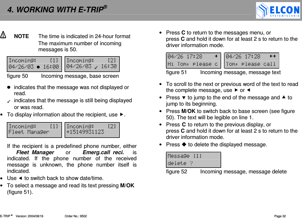
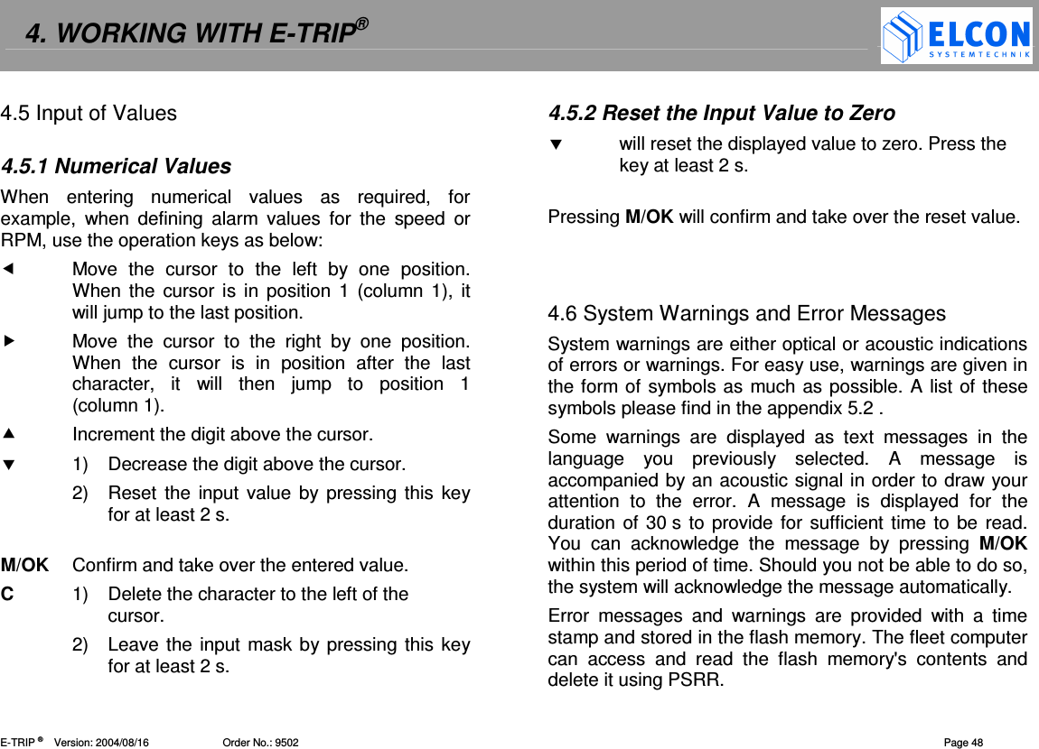
![4. WORKING WITH E-TRIP® E-TRIP ® Version: 2004/08/16 Order No.: 9502 Page 26 After the call of the function “Drivers Log” the current date is indicated, see figure 36. When displaying the Drivers Log data two display modes are available. • use and for next and previous screen of summary data. The following screens are available: 1) Date 2) Total distance of the vehicle in miles or kilometers. 3) Driver ID 4) Driven distance today of driver shown in “Driver ID”. 5) Duration 1: OFF DUTY time of the driver shown in “Driver ID”. 6) Duration 2: SLEEPER time of the driver shown in “Driver ID”. 7) Duration 3: DRIVING time of the driver shown in “Driver ID”. 8) Duration 4: ON DUTY time of the driver shown in “Driver ID”. • use to change to previous day. • use to change to next day. • use ♦♦♦♦ (softkey 4) to change between summary data and detailed data screen. • Press C to abort displaying Drivers Log. Change to the detailed data screen, to transfer drivers duty status into blank logs, see figure 37. On detailed data screen, the following data is indicated: 1) upper left: date 2) upper right: [actual index / maximum index] 3) lower left: duty status start time 4) lower right: duty status -,. ?.%@ ----figure 37 duty status of drivers log • use to change to previous day. • use to change to next day. • use ♦♦♦♦ (softkey 4) to change between detailed data and summary data screen. • Press C to abort displaying Drivers Log. If there is ????-.--.--.--.-@@@@ indicates in the upper right corner of the display, then no entries exist for the duty status for the desired day, see figure 38. -,.!?-.-@ ----&3figure 38 duty status unknown If the data of another driver is to be indicated, the Driver ID of this driver must be entered or the driver card inserted into the smard card reader slot, see chapter Driver ID on page 27.](https://usermanual.wiki/ELCON-Systemtechnik/6600.Operating-Manual/User-Guide-460545-Page-26.png)
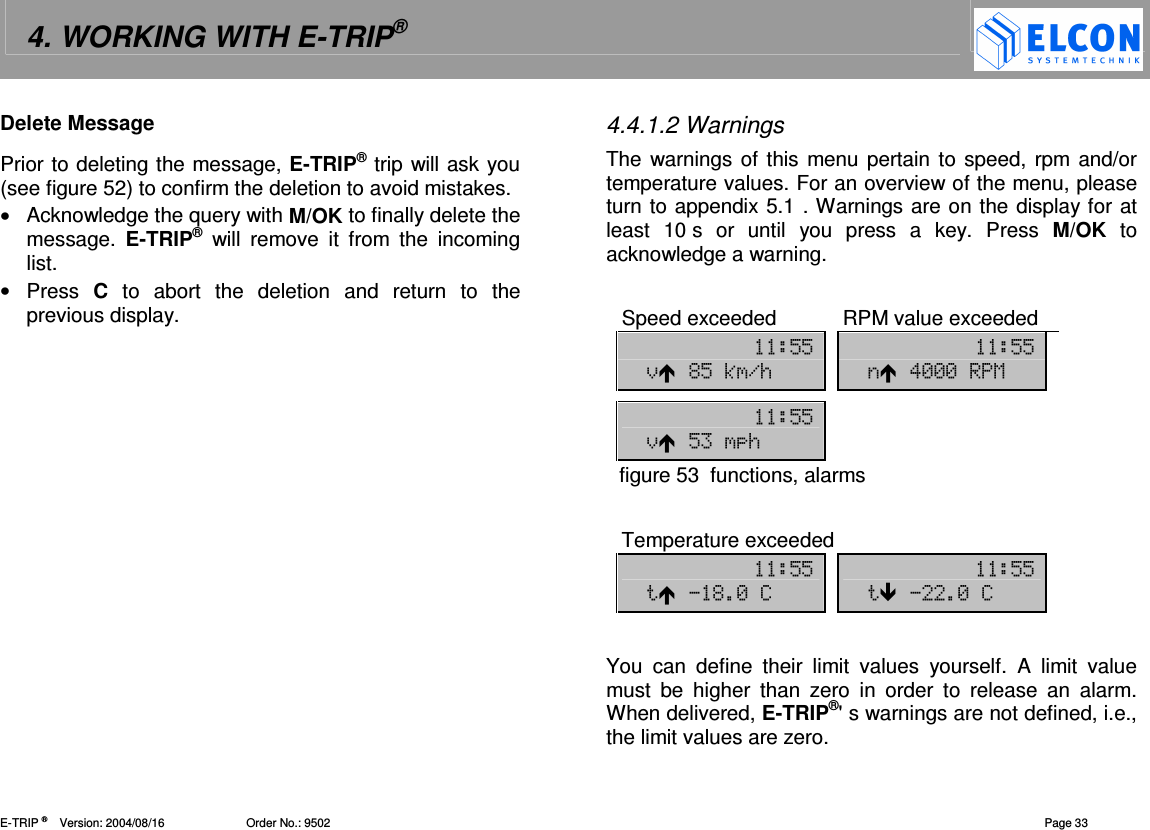
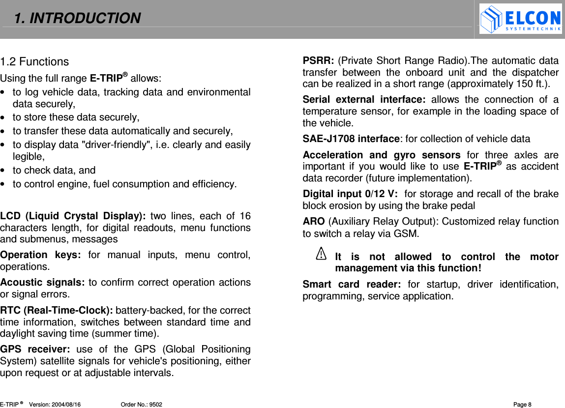
![4. WORKING WITH E-TRIP® E-TRIP ® Version: 2004/08/16 Order No.: 9502 Page 31 To send one of the predefined messages, • select the text you would like to send from the list using and . • Press M/OK to acknowledge the selected message and send it to a predefined phone number (see Message Setup on page 44). If the text has not been sent, an error message will be displayed and this message is added to the outgoing list, see Outgoing Message The number of the text will be displayed on the first line in the right corner. The arrow preceding the index points into the direction you can scroll to display the rest of the message should the text be too long to be displayed in total. [50]: All characters of the message No. 50 are displayed. [50]: The beginning of the message is displayed. [50]: The end of the message is displayed. [50]: Both the beginning and the end of the message are not displayed. 12?"-@=3:*figure 47 Text selection, example Incoming Message You can receive messages via GSM or satellite (ORBCOMM) and E-TRIP® will indicate this both acoustically with a tone sequence and visually on the display and by LED (see chapter 5.4 ). ---!.#.- 12figure 48 Incoming message • Select the menu Functions Messages.. Incoming 2/1 12 =2.figure 49 Incoming message, menu The two numbers after the menu command Incoming indicate the number of messages in the incoming list (first value) and messages still being displayed or read (second value). • To scroll in the list of incoming messages (see figure 50), use and . The display will show date/time message and the text number in the upper right corner.](https://usermanual.wiki/ELCON-Systemtechnik/6600.Operating-Manual/User-Guide-460545-Page-31.png)