ELCON Systemtechnik 6618B EasyTrack 6618B User Manual Manual
ELCON Systemtechnik GmbH EasyTrack 6618B Manual
UserManual.wiki
>
ELCON Systemtechnik
>
6618B User Manual
Manual
Navigation menu
Upload a User Manual
Namespaces
Wiki Guide
HTML
PDF
Info
Views
User Manual
Discussion / Help
Navigation

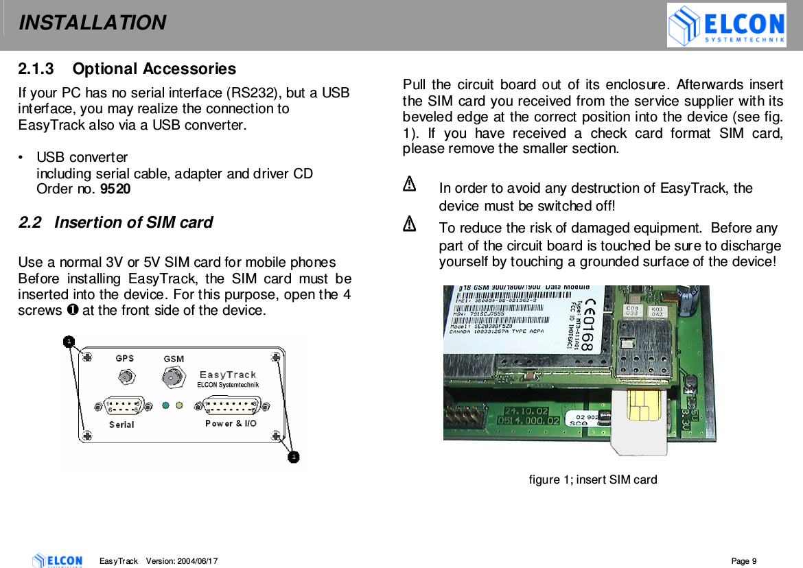
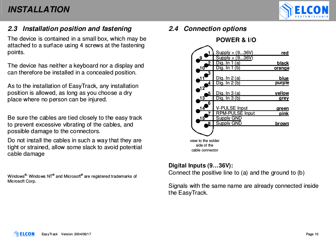
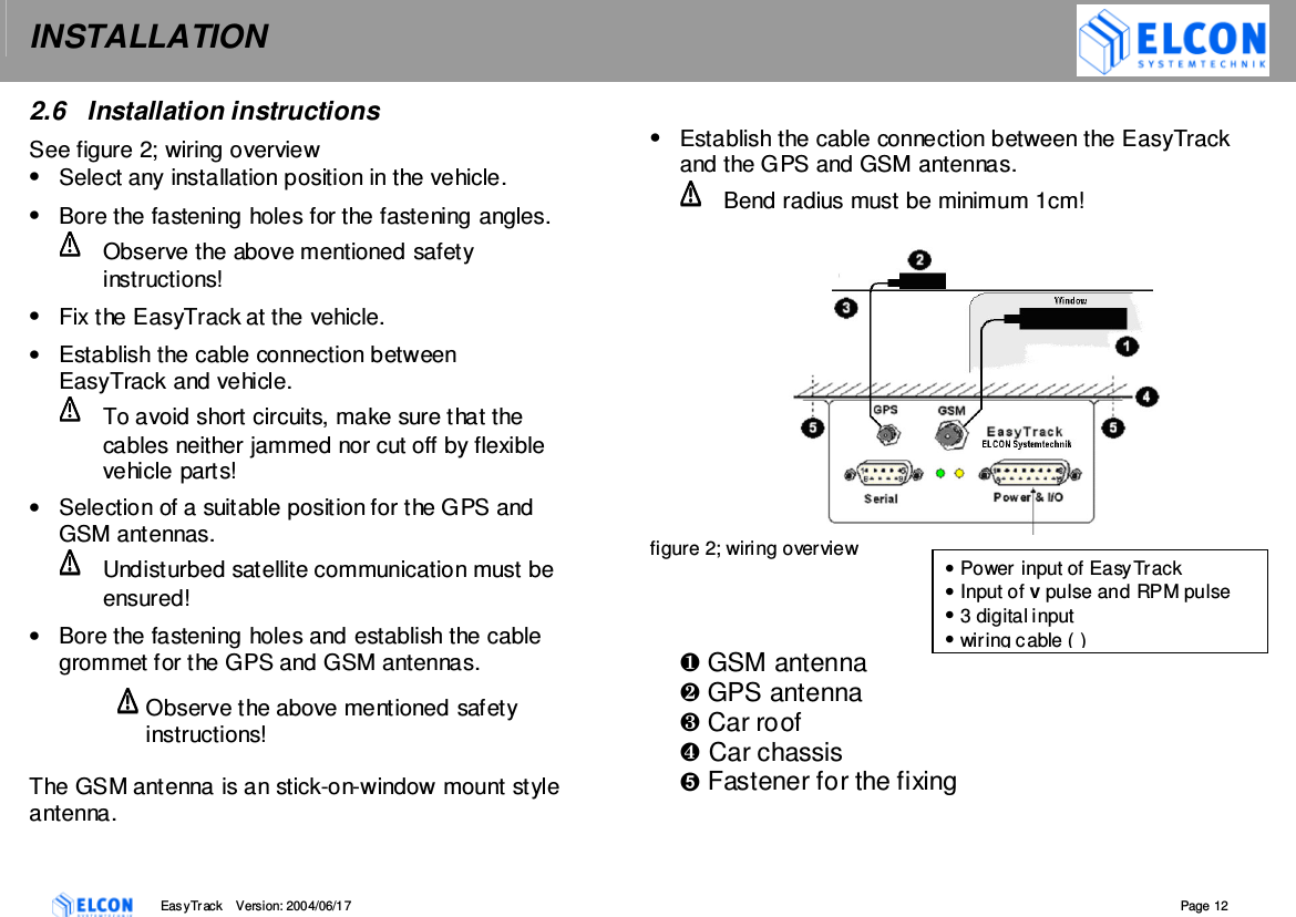
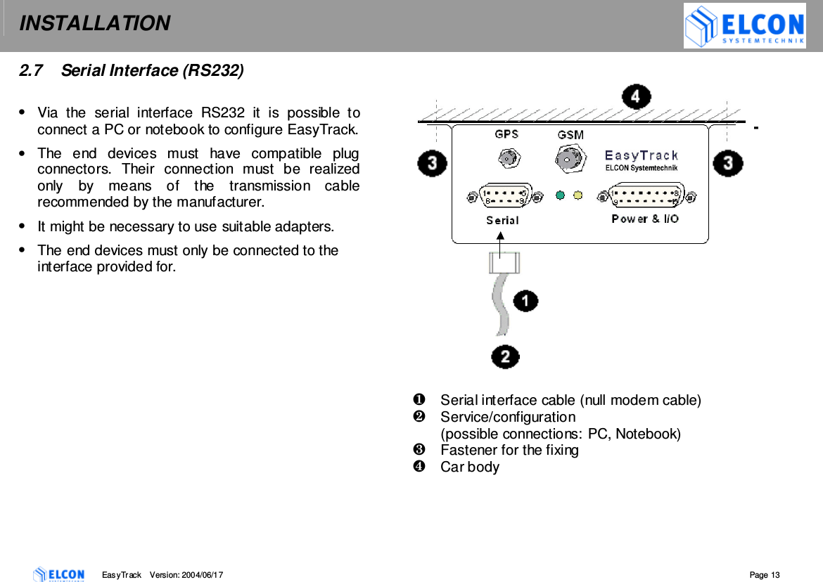
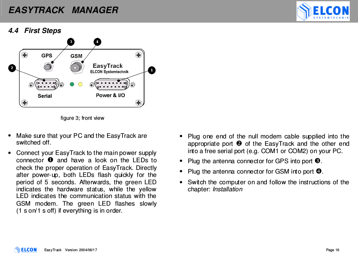
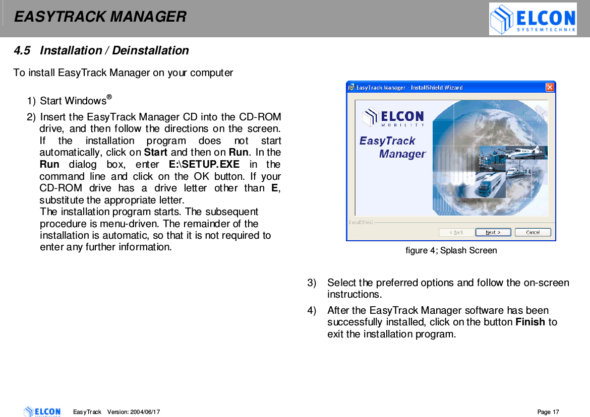
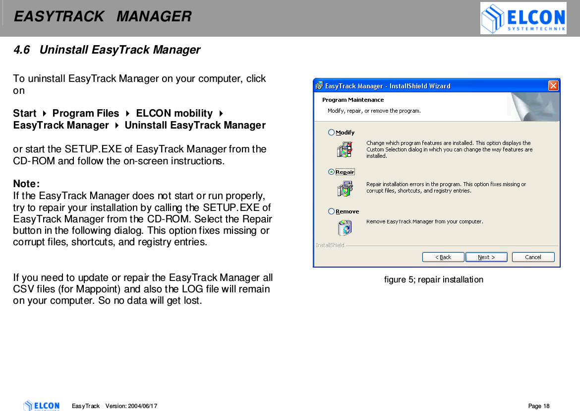
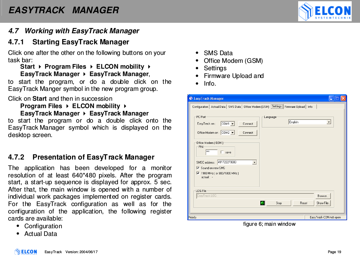
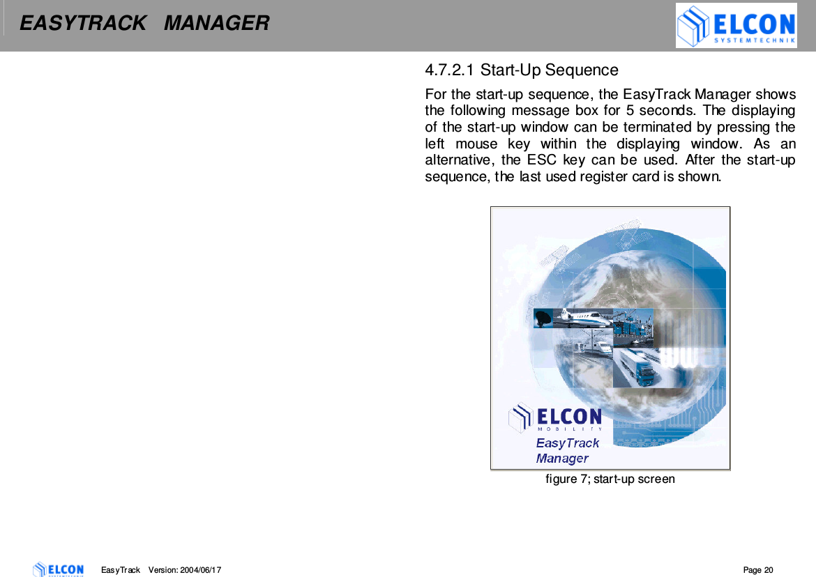
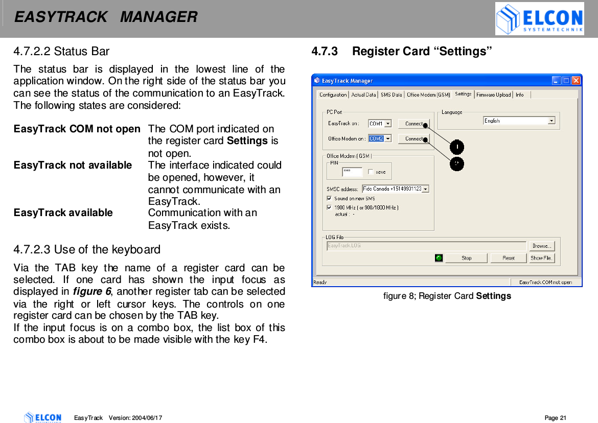
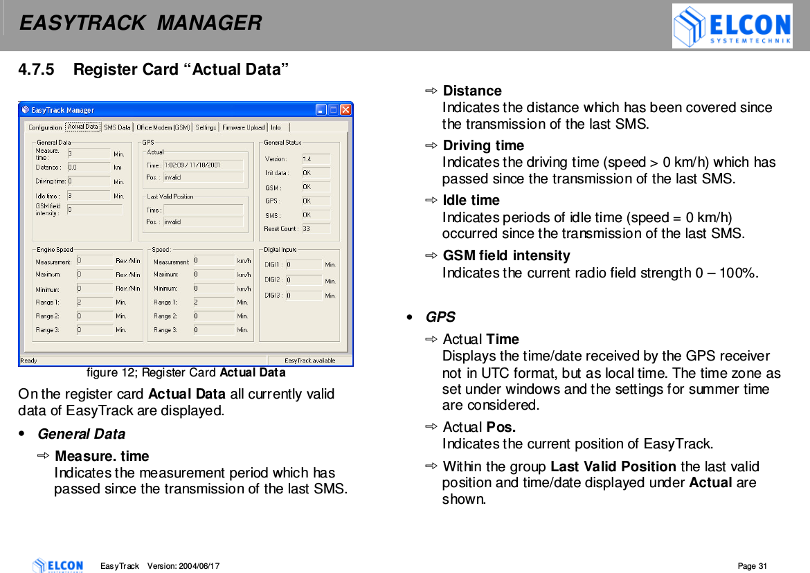
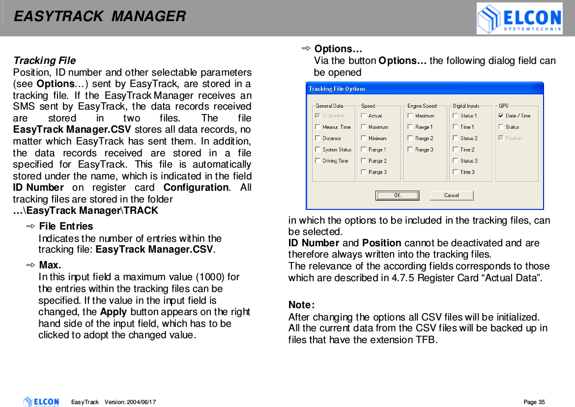
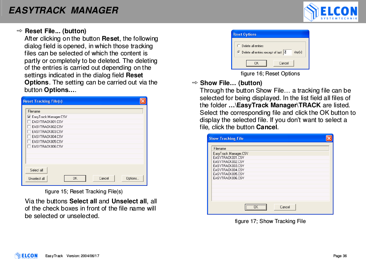
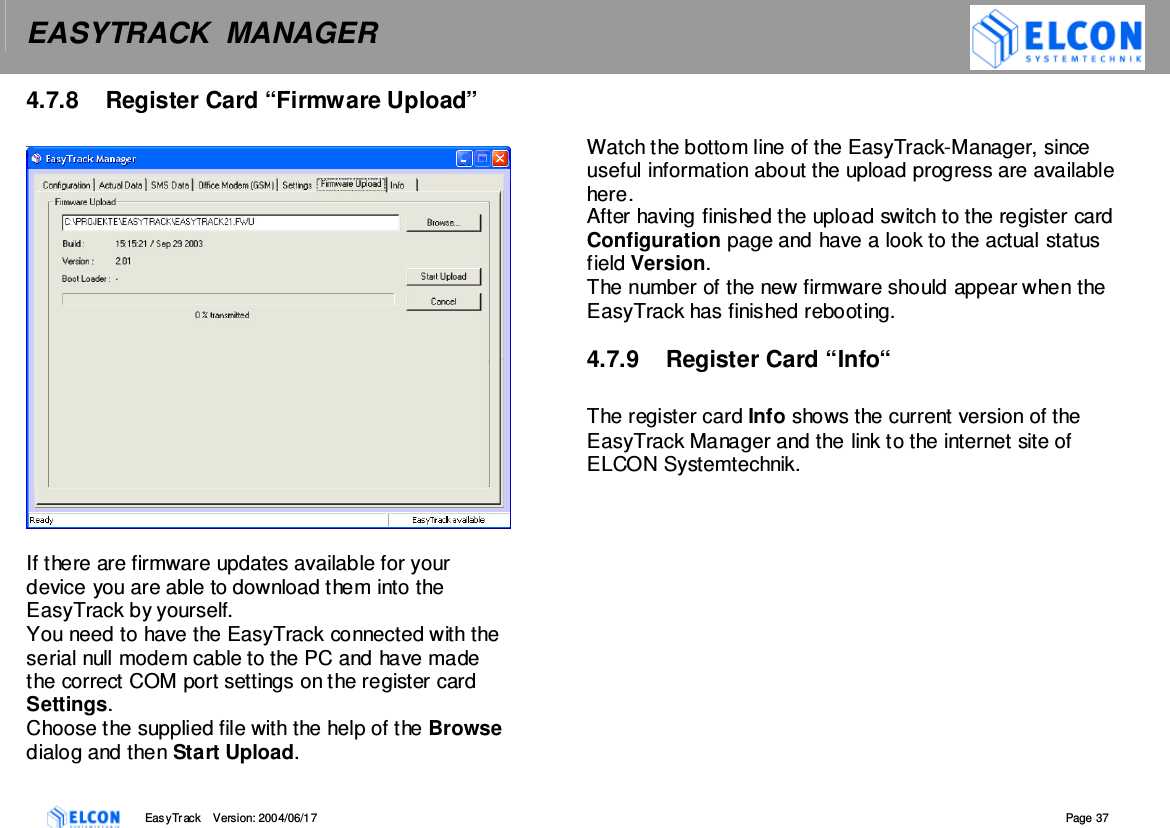
![EASYTRACK MANAGER EasyTrack Version: 2004/06/17 Page 34 4.7.7 Register Card “Office Modem (GSM)” figure 14; Register Card Office Modem (GSM) On the register card Office Modem (GSM) all SMSs received by the office modem are displayed within a list field. In the event of a reboot of the EasyTrack Manager, all entries stored in this list before, get lost. • List Items In the input field List Items the maximum value for the entries within the list field can be specified. A maximum of 100 list entries can be displayed. • Clear List (button) The button Clear List can be used to delete the content of the list field. • Apply (button) The button apply is indicated in the position of the button Clear List, if the value in the input field List Items has been changed. The changed value is adopted by clicking the button Apply. • Start [or Stop] (button) The button Start or Stop can be used to start or to stop the entries in a so-called Tracking File. If the button Start is clicked, its activation is indicated by a green LED. If the writing is deactivated, it is indicated by a red LED.](https://usermanual.wiki/ELCON-Systemtechnik/6618B/User-Guide-462144-Page-34.png)