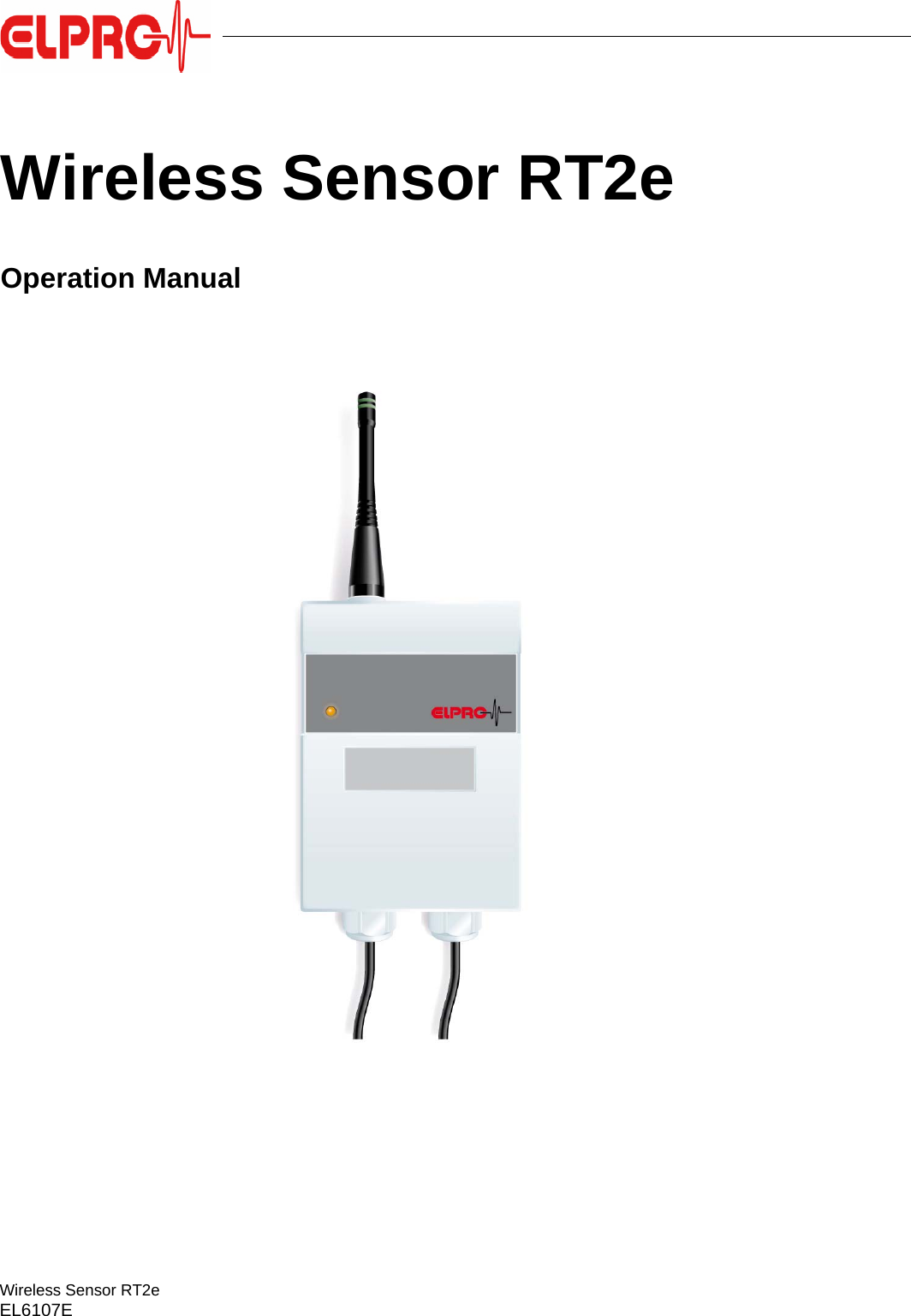
ELPRO BUCHS E11645398 Wireless Sensor User Manual el6107E Wireless Sensor RT2e

ELPRO-BUCHS AG Wireless Sensor el6107E Wireless Sensor RT2e

User Manual

Wireless Sensor RT2eEL6107EWireless Sensor RT2eOperation Manual
2 - EN Wireless Sensor RT2eEL6107E
EN - 3Wireless Sensor RT2eEL6107EITESENENFRITESTable of Contents1. Product description .........................................................................................52. General application and safety information...................................62.1 Antenna position .....................................................................................................62.2 Temperature effect .................................................................................................62.3 Exceptional environmental conditions ....................................................................62.4 Precautionary measures for handling units containing lithium batteries.................73. Wireless Sensor RT2e....................................................................................83.1 Initial startup ...........................................................................................................83.1.1 Transmitted frequency & radio channel.................................................83.2 Operation ................................................................................................................93.3 Maintenance ...........................................................................................................94. Status and error messages ......................................................................105. Technical data....................................................................................................115.1 Radio settings .......................................................................................................115.2  Environment.........................................................................................................125.3 Wireless Sensor RT2e - 2 external temperature sensors.....................................125.4 Part no. System & Accessories ............................................................................135.4.1  Wireless Sensor RT2e........................................................................135.4.2 Accessories .........................................................................................135.5 Label Locations.....................................................................................................145.6 Dimensional drawing ............................................................................................156. Approvals ..............................................................................................................166.1 ETSI......................................................................................................................166.2 Wireless Communication reliability .......................................................................166.3 FCC ......................................................................................................................176.4 INDUSTRY CANADA ...........................................................................................186.5 Conclusion ............................................................................................................18Index...................................................................................................................................20
4 - EN Wireless Sensor RT2eEL6107ESymbols and description codes usedInformationIMPORTANT INFORMATION AND WARNINGSReference to related chapter or documentCHANGES OR MODIFICATIONS MADE TO THIS EQUIPMENT MAY VOID THE ETSI / FCC AUTHORIZATION TO OPERATE THIS EQUIPMENT.THIS DEVICE COMPLIES WITH PART 15 OF THE FCC RULES AND WITH RSS-210 OF INDUSTRY CANADA. OPERATION IS SUBJECT TO THE FOLLOWING TWO CONDITIONS:(1) THIS DEVICE MAY NOT CAUSE HARMFUL INTERFERENCE.(2) THIS DEVICE MUST ACCEPT ANY INTERFERENCE RECEIVED, INCLUDING INTERFERENCE THAT MAY CAUSE UNDESIRED OPERATION.- This product is subject to CE marking.- The manufacturer guarantees that this product complies with the relevant guidelines: EN 61000-6-2 : 2001 and EN 61000-6-4 : 2001- FCC ID: Z45-E11645398- IC: 9954A-E11645398- This product must be disposed of in accordance with WEEE (Waste electrical and electronic equipment, 2002/96/EC)!In the interest of our customers, we reserve the right to make changes due to ongoing technical development. As a result, images, descriptions and scope of delivery are not binding! The release of this document is available on the printed and archived original only.This manual is valid for firmware version 1.02 elproLOG ANALYZE 3.63
EN - 5Wireless Sensor RT2eEL6107EProduct descriptionITESENENFRITES1. Product descriptionThe Wireless Sensor RT2e works autonomously and is supplied with power via internal batteries.On the front side there is a status display (green/red LED) and a type label which documents the wireless sensor designation and the ID number of the sensor.1.Aerial2.Status display  3.2 Operation3.Type label with ID numbers4.3 batteries for the types inside the wireless sensor5.SensorsA wireless sensor can be connected with up to 2 sensing devices.
6 - EN Wireless Sensor RT2eEL6107EGeneral application and safety information2. General application and safety information2.1 Antenna positionRange approx. 1000mThe range (always dependent upon the structural conditions of the building such as cement ceilings, water pipes etc.) is approx. 100m in a typical office environment  5.1 Radio settings.In which direction shouldthe antenna point?With this type of antenna, the signal is emitted at right angles from the antenna. The direction can be visualized as being like a CD that is skewered on the antenna. This makes it clear that it is best for the antenna to be placed vertically, pointing upward, so that it transmits to all rooms on the same floor. If the antenna is placed horizontally, reception is best on the floors above and below.Metal objects such as shelves, reinforced concrete walls, ventilation and energy shafts, but also the opening of a refrigerator door can lead to the weakening of the signal. This kind of effect is usually very much limited to the location.Moving the wireless sensor within an area of 2.5 meters (sometimes just a few centimeters) is usually adequate to completely change the reception (  3.1.1 Transmitted frequency & radio channel). Move the wireless sensor forward, backward, up and down within this area. The wireless sensor should always be mounted at least 1.5m above the ground.If no direct line of sight to the wireless sensor is available, the angular position (angle in relation to the horizontal axis and rotation of direction) can improve reception.Placing the wireless sensors in an open stairwell is an additional possibility to avoid one or more reinforced steel ceilings that are an obstacle.For additional details regarding the antennas  5.1 Radio settings2.2 Temperature effect- For the range of application,5. Technical data.- It can't be guaranteed that the loggers will function properly if the datalogger is exposed to temperatures which exceed the specified threshold range. Experience shows that at storage temperatures below -50°C, the battery freezes, measurements are no longer taken and setpoint tracking may be temporarily interrupted. Once it has been returned to room temperature, the logger must be reprogrammed before it can be used again.- At temperatures below - 20°C, the display is not easily readable; however, longterm use is not affected.- For longterm use above 40°C, lithium battery passivation can lead to temporary reading problems (self-discharge protection), which can be resolved with repeated utilization.- At temperatures above 45°C, battery self-discharging increases. With long term use above 45°C, the battery lifetime can be reduced by about 1/3. - Exposure to temperatures above 55°C can result in permanent discoloration of the display.- There is danger of a gas explosion if the lithium battery is heated to temperatures exceeding 100°C.2.3 Exceptional environmental conditionsPay attention to the following when using the wireless sensor in exceptional environmental conditions:- IR radiation (heat) and superheated steam can damage the surface coating of the casing- There is a risk that the battery may explode if the logger is used under microwave radiationInitial startupTHE WIRELESS SENSOR MUST BE AT ROOM TEMPERATURE BEFORE INITIAL STARTUP!
EN - 7Wireless Sensor RT2eEL6107EGeneral application and safety informationITESENENFRITES2.4 Precautionary measures for handling units containing lithium batteriesLithium batteries- Do not short-circuit and charge batteries: Explosion hazard- Do not throw units which contain batteries into fire: Explosion hazard- Do not subject batteries to mechanical stress and do not dismantle them as leaking battery fluid is highly corrosive and lithium can generate severe heat or can ignite a fire if it comes into contact with moisture.- Do not heat battery operated units to temperatures exceeding 100°C: Explosion hazard- Avoid excessive impact- Follow the manufacturer specifications for storing batteries- Return batteries to the supplier for correct waste disposal
8 - EN Wireless Sensor RT2eEL6107EWireless Sensor RT2e3. Wireless Sensor RT2e3.1 Initial startupThe wireless sensor casing contains various operating equipment, 3 batteries and the sensor connections.Technical data and the assignment of terminals in the :SENSORS" field  5.3 Wireless Sensor RT2e - 2 external temperature sensors.BatteriesThe wireless sensor uses 3 lithium 3.6V batteries. The battery capacity is sufficient for operation time of 2 - 3 years.Replacement batteries   5.4.2 AccessoriesBATTERY ERRORThis LED lights up red when the battery is inserted incorrectly.SET keyThe battery counter is reset by pressing and holding the SET key (6 seconds).3.1.1 Transmitted frequency & radio channelThe frequency band setting is factory hard-wired. The set frequency band is marked on the top side of the pcb during manufacturing.The radio channel used is defined using the positions of the internal rotary switch.SET keyBy quickly pressing the SET key (1 second), the settings are acknowledged and the test of the radio connection is started. The test lasts approx. 2 seconds. The test result is represented by repeated color blinking in the status display at a rate of 1 per second.RT2e 2 external PT100 temperature sensorsThe external PT100 sensors can be used with 3- or 4-wire connections.Appropriate  antennas are to be used.
EN - 9Wireless Sensor RT2eEL6107EWireless Sensor RT2eITESENENFRITESIn the event of a poor test result, shifting the wireless sensor can lead to an improvement in the radio connection  2.1 Antenna position.If no radio connection can be established, the channel settings should be checked. Radio channelchangeIf the radio channel needs to be changed during operation, it is necessary to briefly press the SET key after selecting the new channel.3.2 OperationUndisrupted operation is indicated by a green, blinking light of the status indicator at intervals of 10 seconds.Status indicator3.3 MaintenanceMaintenance scheduleTo ensure proper functioning of the wireless sensor, the following steps should be part of a periodic maintenance schedule:- Calibrate wireless sensor- Replace batteries  5.4.2 AccessoriesReplacing batteryMonitoring of the battery is based on an energy consumption count. For this reason, only the specific manufacturer recommended battery should be used. Do not remove the battery from the wireless sensor when it is not in use. The use of third party batteries or removal of batteries will produce incorrect status information at the battery indicator.Status display - test resultQuality of the radio connection Blinks, number Colorgood radio connection 100% 5 green80% 4 green60% 3 green40% 2 greenpoor radio connection 20% 1 greenNo radio connection or wrong settings* 1 redStatus indicator - OperationQuality of the radio connection Blinks, number Colorgood radio connection 1 greenNo radio connection or wrong settings* 1 redAFTER THE BATTERIES ARE CHANGED, THE SET KEY MUST BE PRESSED AND HELD FOR 6 SECONDS, OTHERWISE THE ENERGY COUNTER WILL NOT FUNCTION
10 - EN Wireless Sensor RT2eEL6107EStatus and error messages4. Status and error messagesOperation Blinks green at an interval of 10 secondsFailure The interruption of the radio connection is indicated by a red blinking light at an interval of 10 seconds. Reestablishing the radio connection can take up to 1 minute.Connection test Blinks green / red  3.1.1 Transmitted frequency & radio channel In the housing:BATTERY ERRORThis LED lights up red when if one of batteries is inserted incorrectly.
EN - 11Wireless Sensor RT2eEL6107ETechnical dataITESENENFRITES5. Technical data5.1 Radio settingsAerial• External, omnidirectional• 1/4 wavelengths• Synthetic whip• RP-SMA connection• The range is approximately 1000m in open areas and with line of sightSignal weakeningin airThis example makes the dramatic relation between free space damping and transmission frequency very clear.The damping factor for solid materials is 4 - 6 times higher than the factor for free space damping (air).ChannelFCC (MHz) Color coding of the aerial0 - F 915 yellowFrequency band (MHz) Signal weakening at a distance of:10m 100mdB Factor dB Factor915 51.5 380 71.5 3800
12 - EN Wireless Sensor RT2eEL6107ETechnical data5.2  Environment5.3 Wireless Sensor RT2e - 2 external temperature sensorsSensor connectionThe terminal assignment for the PT100 sensors is presented in the adjacent figure.PT100 sensors with 3 or 4 leads can be used.Connection cablesIn order to guarantee that the sensor cable has good contact, the lead ends should have between 8.5 - 9.5mm of the insulation strippedAmbient temperature -30°C ...55°C, non-condensingProtective class IP30external power supply UB10 ...30VDC24VDC; up to 1.6A startup current, 70mA operationAmbient temperature -30°C ...55°C, non-condensingProtective clase IP54Power supply / operating time 3 internal lithium batteries / 2-3 yearsMeasurement range / sensors -200°C ...200°C / PT100Accuracy 25.1°C ...200.0°C +/- 0.50°C(without sensor) -10.0°C ...25.0°C +/- 0.30°C-200.0°C ...-10.1°C +/- 0.50°CLength sensor cable max. 20m
EN - 13Wireless Sensor RT2eEL6107ETechnical dataITESENENFRITES5.4 Part no. System & Accessories5.4.1  Wireless Sensor RT2e5.4.2 AccessoriesPart no. Function3454-US RT2e wireless sensor - 2 x external temperaturePart no. Name2760-US Aerial 915 MHz band FCC, yellowIncluded in scope of delivery31xx-xx Diverse PT100 sensors2820-A Replacement battery, can be stored for at least 5 years, for wireless sensor
14 - EN Wireless Sensor RT2eEL6107ETechnical data5.5 Label Locations
EN - 15Wireless Sensor RT2eEL6107ETechnical dataITESENENFRITES5.6 Dimensional drawing
16 - EN Wireless Sensor RT2eEL6107EApprovals6. Approvals6.1 ETSIThe standards used in the evaluation of this product establish the threshold values for use in residential areas, business and commercial areas as well as in small businesses whereby the use of the product is intended for a business environment.This includes the following, typical sites and spaces:- Residential buildings/living spaces such as houses, apartments and rooms, etc.;- Retail areas such as stores, supermarkets, etc.;- Business premises such as municipal offices, banks, etc..;- Entertainment businesses such as cinemas, public establishments, etc.;- Outdoor locations such as gas stations, parking lots, sports facilities, etc.;- Small business offices such as workshops, service centers, etc.All areas of application are characterized by the fact that they are connected to the public low-voltage power supply. When using in a location in a severely electromagnetically disrupted environment such as typical industry environments, problems are likely to occur as a result of the product's inadequate interference immunity.R&TTE Guideline 99/5/EGEN 300 220-1 V2.1.1 (2006-04) EN 60950-1 (2006-11)EN 300 220-2 V2.1.2 (2007-06)EN 301 489-1 V1.8.1 (2008-04)EN 301 489-3 V1.4.1 (2002-08)EMV Guideline 2004/108/EGEN 55022 (2008-05)EN 50130-4 (2003-09)EN 50371 (2002-11)Low Voltage Directive 2006/95/EGEN 60650-1 (2006-11)EN 61000-6-1 (2007-10)EN 61000-6-3 (2007-09)6.2 Wireless Communication reliabilityThe communication reliability for the Elpro radio sensor system, often referred to as Quality of service (QoS) is based on the following principles:"The used modulation is of the "Gaussian Frequency-Shift Keying (GFSK)" type. This is a type of frequency shift keying modulation that uses a Gaussian filter to smooth positive/negative frequency deviations:- FCC compatible- Address match for detection of incoming package - Automatic retransmission of data packages - Automatic CRC and preamble generation- Build in test function for the radio signal- Use of frequency  hopping in the 915MHz band- Limited number of sensors and transmitters used- Installation requirementsRisk assessment for Receivers and TransmittersThe Elpro wireless system is made up of a receiver and a transmitter function in the wireless datalogger and in each radio sensor. The receivers are divided into three classes, each having its own set of minimum performance criteria. The classification is based upon the impact the equipment has on persons in case of a failure.The Elpro radio sensor system complies to a class 2 system:A failure causes loss of function but not physical risk of a person
EN - 17Wireless Sensor RT2eEL6107EApprovalsITESENENFRITES6.3 FCCIn the USA, the FCC (Federal Communications Commission) regulates the use of frequencies for RFequipment. CFR 47 part 15 (Code of Federal Regulations) covers the unlicensed ISM bands. This is usually referred to as FCC part 15. All equipment must be certified with the FCC with the issuance of a Grant of Authorization by the FCC. When the product is approved, the FCC issues an identification number which the product must be marked with.The part 15 sections for ISM band radios are:- 15.19 / RSS-210: Manual requirements- 15.35: General rules for certification measurements- 15.105: Manual requirements- 15.109: Radiated emission limits for unintentional radiators- 15.205: Restricted bands of operation- 15.209: Radiation limits for intentional radiators- 15.247: Frequency Hopping and Spread Spectrum (FHSS), operation within the bands 902 - 928MHz, 2400 - 2483.5 MHzSpurious emissions and restricted bandsA large part of the FCC Part 15 is about the limit of spurious emissions (harmonic component) andrestricted bands. The main concept behind part 15 is that a general set of rules must be followed, but with exceptions for different application and frequency bands.Emissions are divided into two parts:- Unintended radiators, like receivers and transmitters in standby or other radiators requirements are given in 15.109- Intended radiators, like active transmitters requirements are given in 15.209There are a number of restricted frequencies according to 15.205 which cannot be used for active transmissions, but spurious emissions can be produced. The levels are given in EIRP, Electrical Field Strength Power, at a distance of 3 metersWhite Paper915MHz bandSection 15.249 gives the opportunity to use the 902-928MHz band with an output power of 50mV/m at 3 meters or -1.2dBm. The harmonics are limited to 500uV/m or -41.2dBm. This band is commonly referred to as the 915MHz band in the USA. There are no restrictions on duty cycle or the application.Even higher output power can be used according to section 15.247. This implies the use of frequency hopping. The following requirements must be fulfilled for the use of the 902-928MHz band under section 15.247:- Hopping channels shall be separated by minimum 25 kHz or the 20dB bandwidth of the hopping channel, whichever is greater.- The system shall hop to channel frequencies that are selected at the system hopping rate from a pseudorandomly ordered list of hopping frequencies.- If the 20 dB bandwidth of the hopping channel is less than 250 kHz, the system shall use at least 50 hopping frequencies and the average time of occupancy on any frequency shall not be greater than 0.4 seconds within a 20 second period.- If the 20 dB bandwidth of the hopping channel is 250 kHz or greater, the system shall use at least 25 hopping frequencies and the average time of occupancy on any frequency shall not be greater than 0.4 seconds within a 10 second period.- The maximum allowed 20 dB bandwidth of the hopping channel is 500 kHz.- Maximum peak conducted output power is 1W in the 902-928MHz band if more than 50 hopping channels are used. The limit is 0.125W for 25 to 50 hopping channels.Frequency Electrical Field Strength EIRP216-960MHz 200mV/m -49.2dBm
18 - EN Wireless Sensor RT2eEL6107EApprovalsFCC STATEMENT This product has been tested and complies with the specifications for a Class B digital device, pursuant to Part 15 of the FCC Rules. These limits are designed to provide reasonable protection against harmful interference in a residential installation. This equipment generates, uses, and can radiate radio frequency energy and, if not installed and used according to the instructions, may cause harmful interference to radio communications.However, there is no guarantee that interference will not occur in a particular installation. If this equipment does cause harmful interference to radio or television reception, which is found by turning the equipment off and on, the user is encouraged to try to correct the interference by one or more of the following measures:- Reorient or relocate the receiving antenna- Increase the separation between the equipment and receiver- Connect the equipment to an outlet other than the receiver's- Consult a dealer or an experienced radio/TV technician for assistanceRadiation Exposure Statement This equipment complies with FCC radiation exposure limits set forth for an uncontrolled environment. This equipment should be installed and operated with minimum distance 20cm between the radiator and your body.6.4 INDUSTRY CANADAThis Class B digital apparatus complies with Canadian ICES-003, RSS210.The use of this device in a system operating either partially or completely outdoors may require the user to obtain a license for the system according to the Canadian regulations.6.5 ConclusionThe data transfer between wireless dataloggers and radio sensors could be seen as a safe way to exchange data.This conclusion is valid as long as the wireless datalogger system is secured against any kind of fraud from the inside or outside of the company. This security task has to be fulfilled by the company internal IT department or other related departments.Further information More information regarding rules and requirements are found at:http://www.fcc.govETSI standards are found at:http://www.etsi.orgThe CEPT/ERC rec 70-03 are found at:http://www.ero.dkThe ARIB STD-T66 regulation is found at:http://www.arib.or.jp/english/index.htmlThe Australian/New Zealand Standard AS/NZS 4268:2003 are found at:http://www.standards.org.au
EN - 19Wireless Sensor RT2eEL6107EApprovalsITESENENFRITES
EN - 20Wireless Sensor RT2eEL6107EITESENENFRITESRevision HistoryAuthor Date Version DescriptionA. Gubler 26.06.2012 -- First edition
21 - EN Wireless Sensor RT2eEL6107EIndexNumerics3 / 4 wires 12AAccuracy 12Aerial 8, 11Ambient temperature 12BBatteries 8, 9Battery counter 8BATTERY ERROR 8, 10CChannel 11EEnvironmental conditions 6Error messages 10ETSI 16FFCC 17IID number 5Initial startup 6MMaintenance schedule 9Measurement range 12PPower supply 12Precautionary measures 7Protection class 12PT100 8PT100 2/3 lead 12RRadio channel 8Radio connection 8Replacing battery 9SSensor cable 12Sensor connection 12SET key 8Signal weakening 11Special environmental conditions 6Status indicator 8, 9TTemperature influence 6
Operation ManualWireless Sensor RT2eEL6107E 08.2012(Head Office)ELPRO-BUCHS AGLangäulistrasse 62CH-9470 Buchs SGSwitzerlandemail: swiss@elpro.comFor local representatives see:www.elpro.comwww.pdf-datalogger.com

Navigation menu