ENUSTECH EZBL100 wireless link User Manual
ENUSTECH wireless link
UserManual.wiki
>
ENUSTECH
>
EZBL100 User Manual
User manual
Navigation menu
Upload a User Manual
Namespaces
Wiki Guide
HTML
PDF
Info
Views
User Manual
Discussion / Help
Navigation
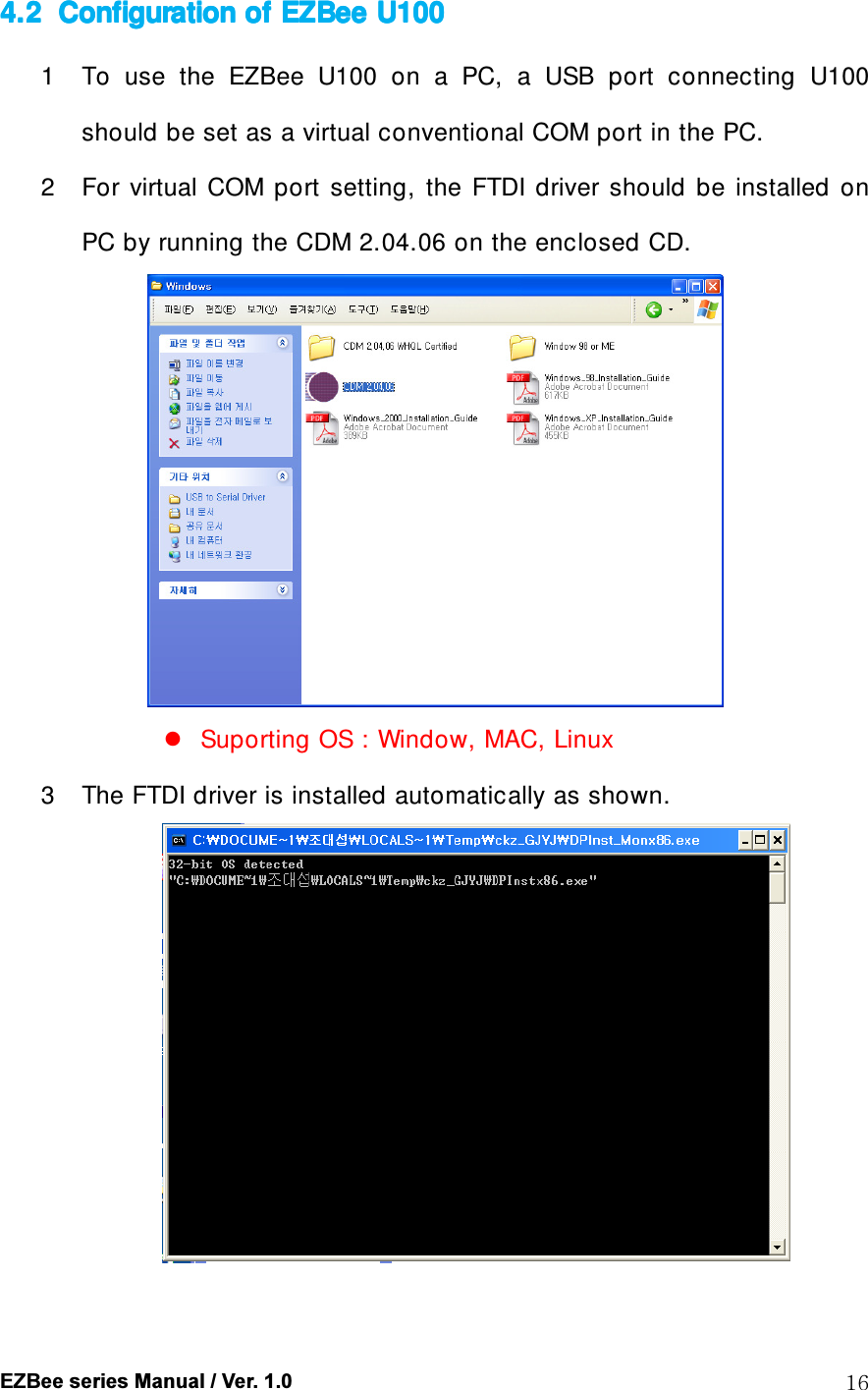
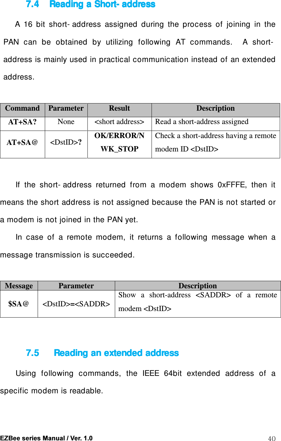
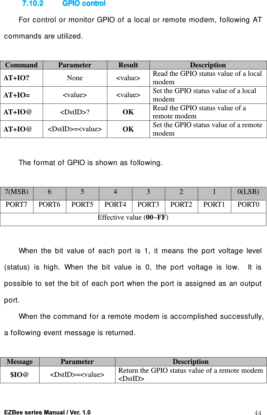
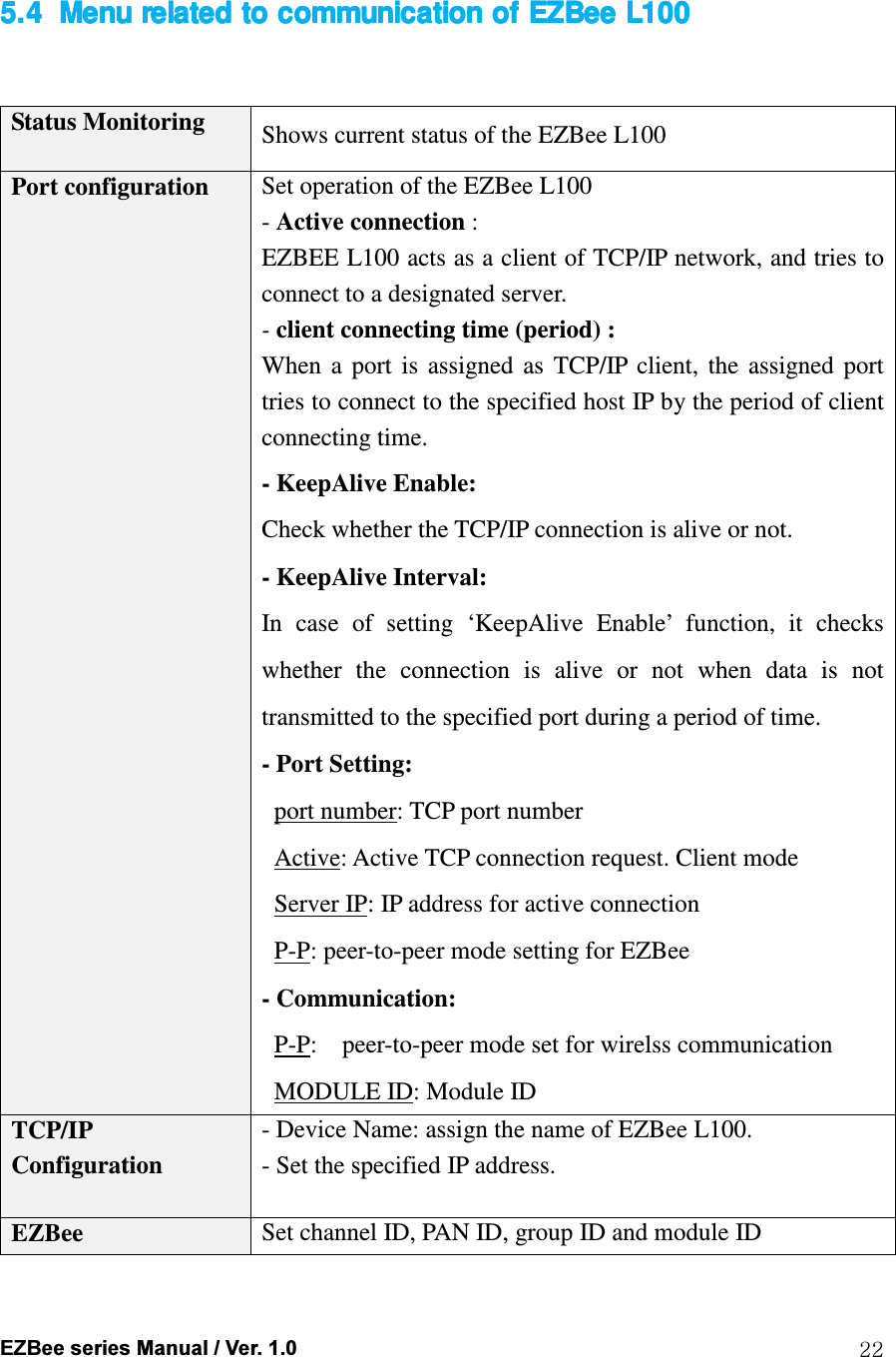
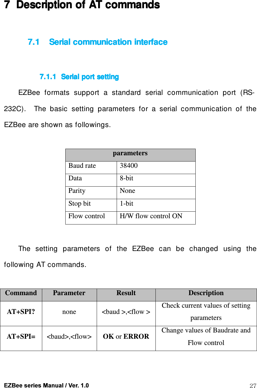
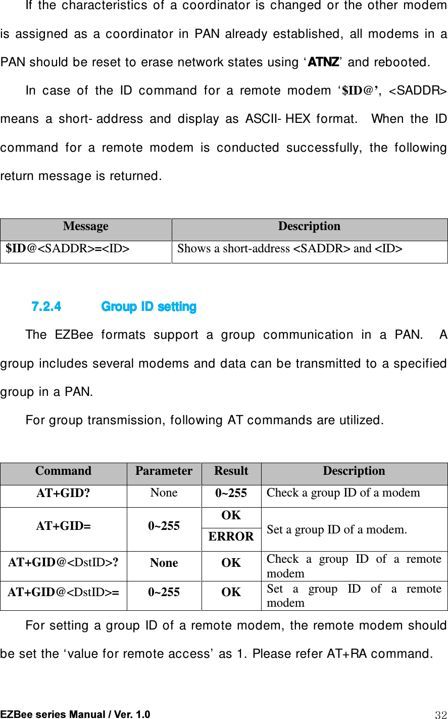
![EZBee series Manual / Ver. 1.0 20 to default IP. 2 Type enus as the default password 3 After set your network IP at [ TCP/ IP configuration ] , reboot the EZBee L100.](https://usermanual.wiki/ENUSTECH/EZBL100/User-Guide-1034305-Page-20.png)
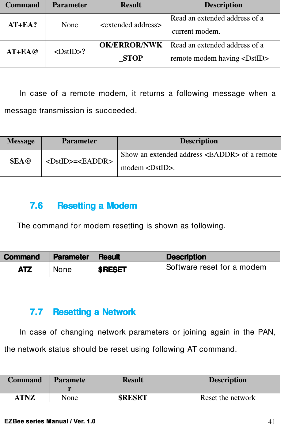
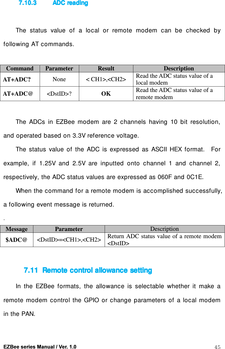
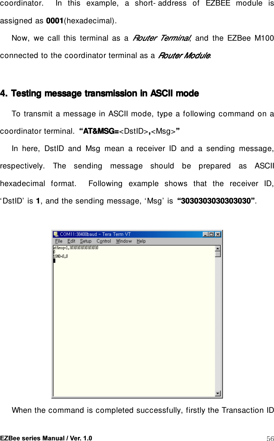
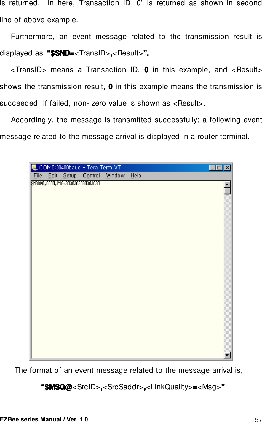
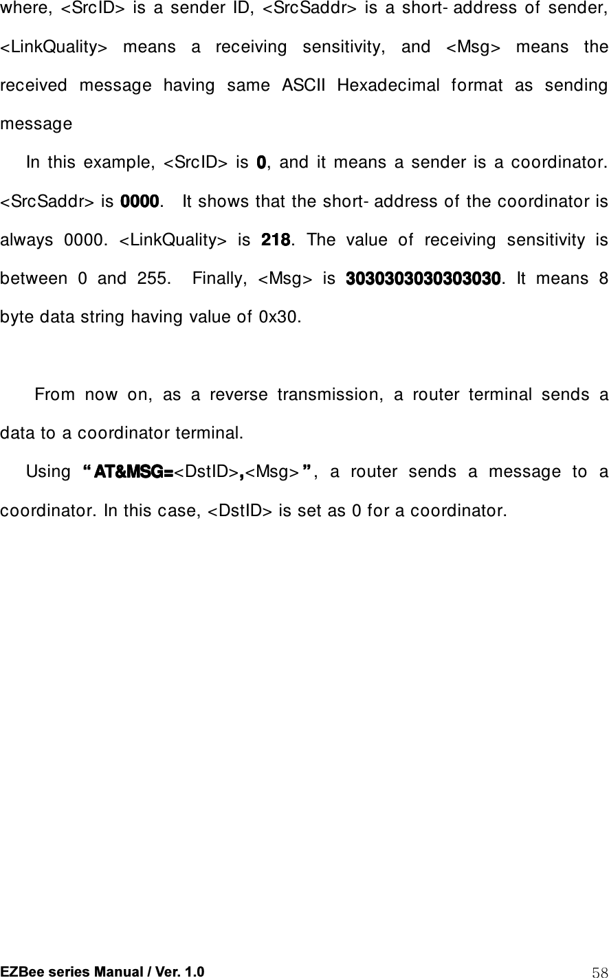
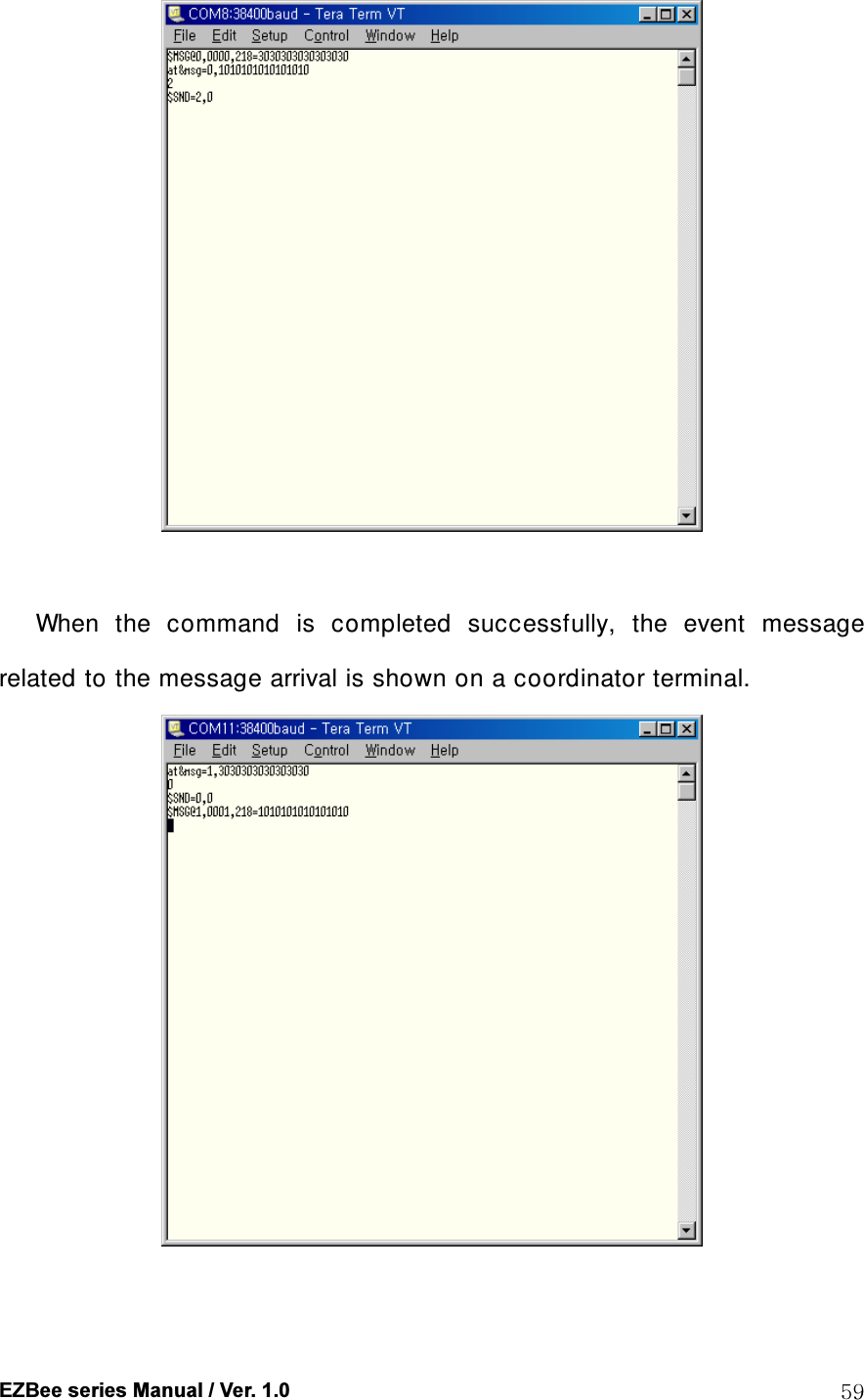
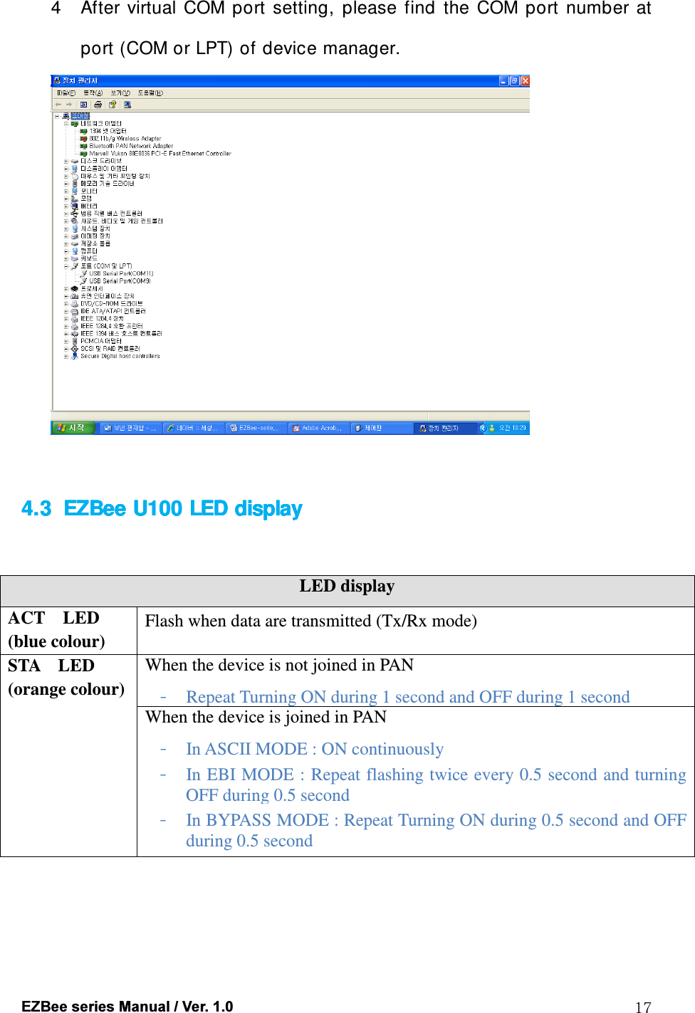
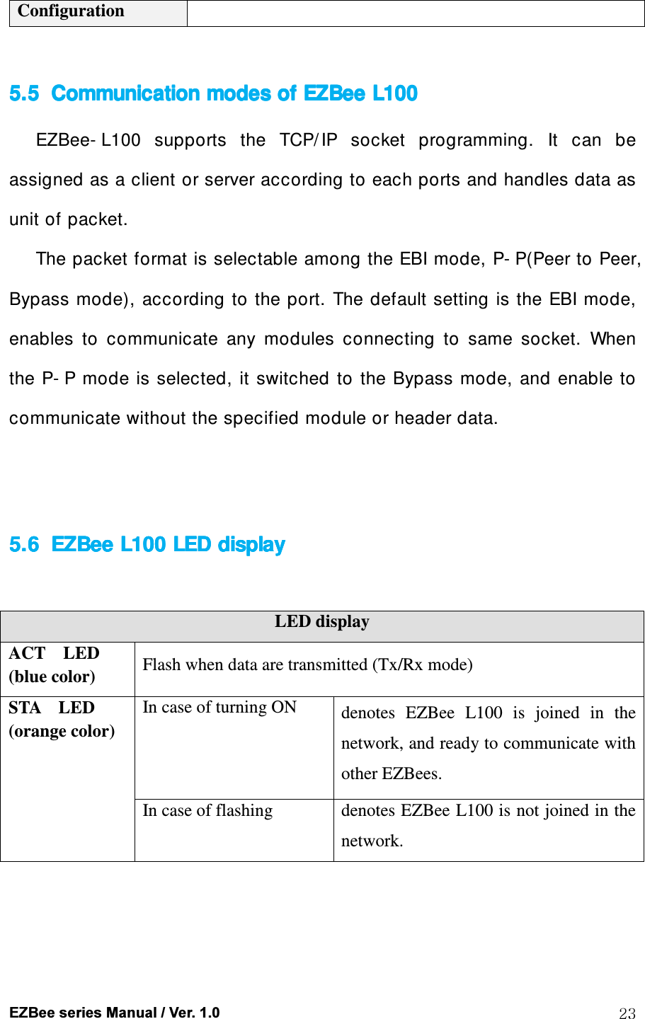
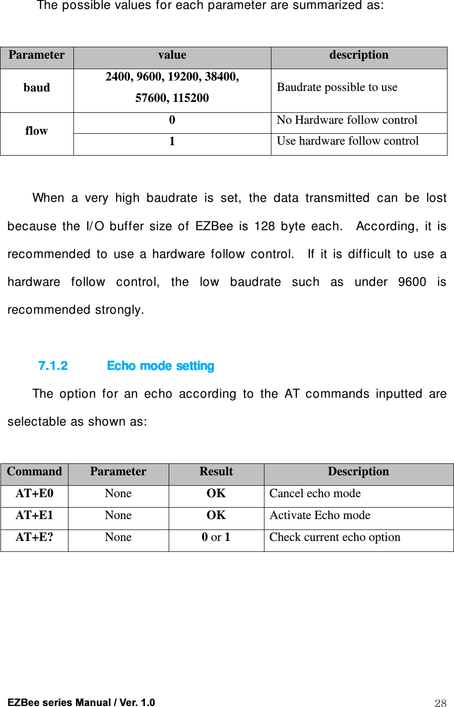
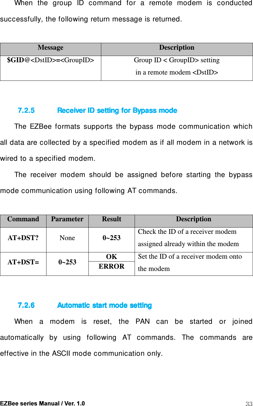
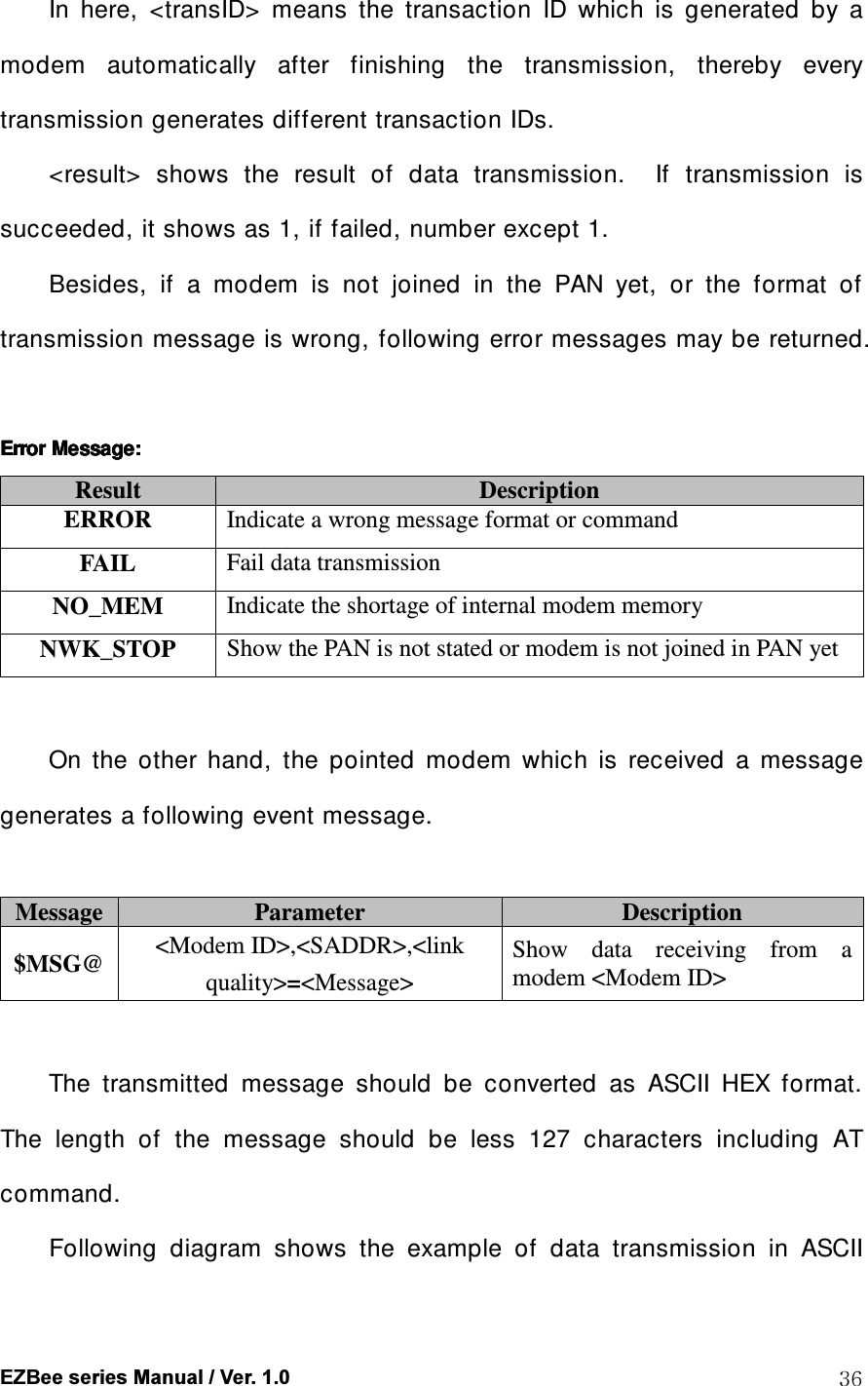
![EZBee series Manual / Ver. 1.0 21 5.3.25.3.25.3.25.3.2 Using Using Using Using EZBee EZBee EZBee EZBee manager manager manager manager programprogramprogramprogram The EZBee manager program is an utility program developed for easy setting and management of a EZBee L100. Useful function for setting : <scanning broadcasting device> The useful function of the EZBee manager program is a scanning broadcasting device. It searches and shows all list of EZBee L100 connecting to the same network of a user computer. 1 Click the button denoting [start search]. 2 A list of all EZBee L100 connecting to the network is displayed when the automatic scanning is over. 3 When you want to change the setting of one U100 among the list, move the mouse point onto that EZBee L100 and just click the right button of a mouse, then you can change the parameter from the displaying menu.](https://usermanual.wiki/ENUSTECH/EZBL100/User-Guide-1034305-Page-21.png)
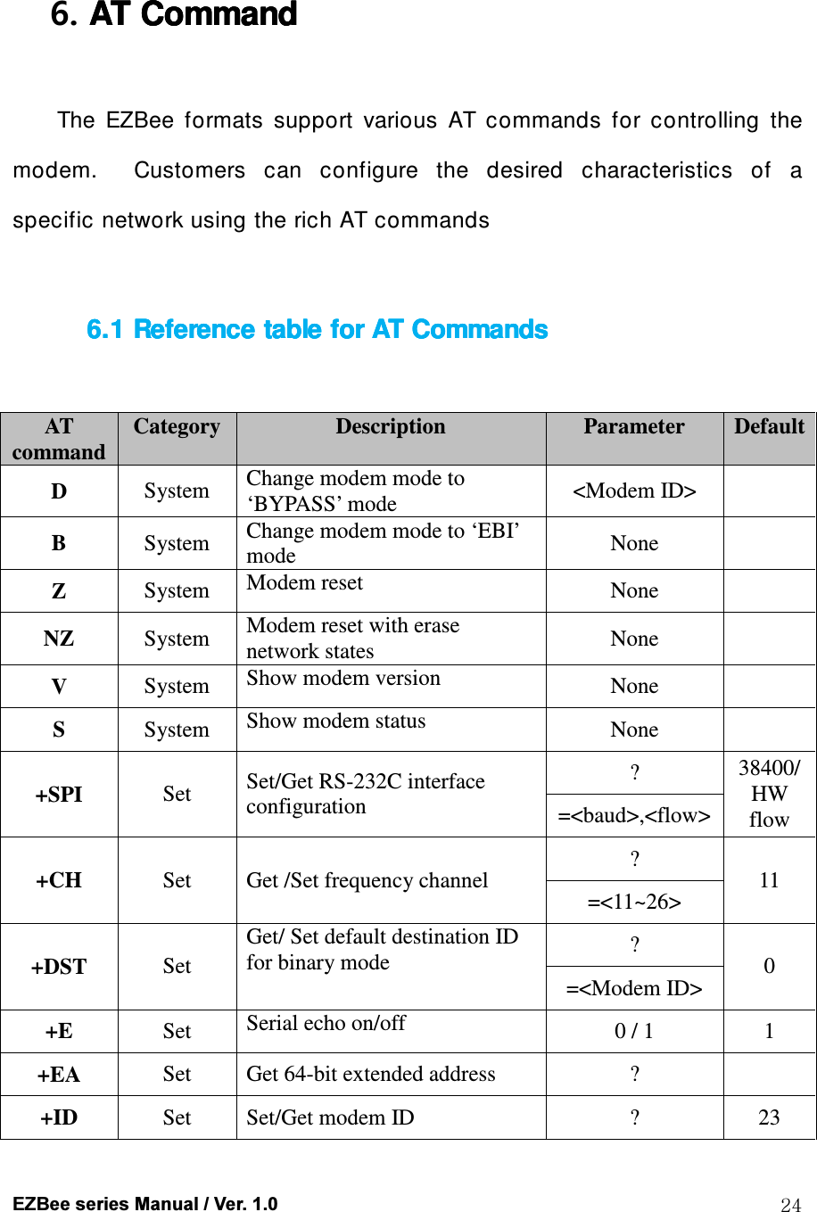

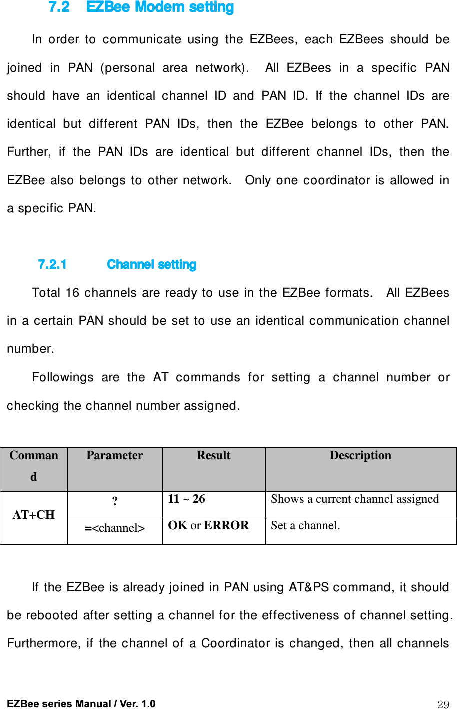
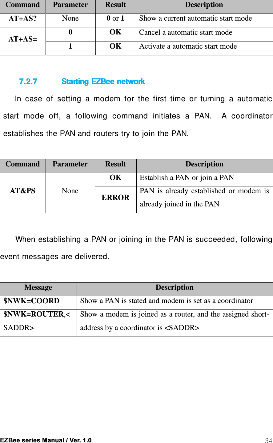
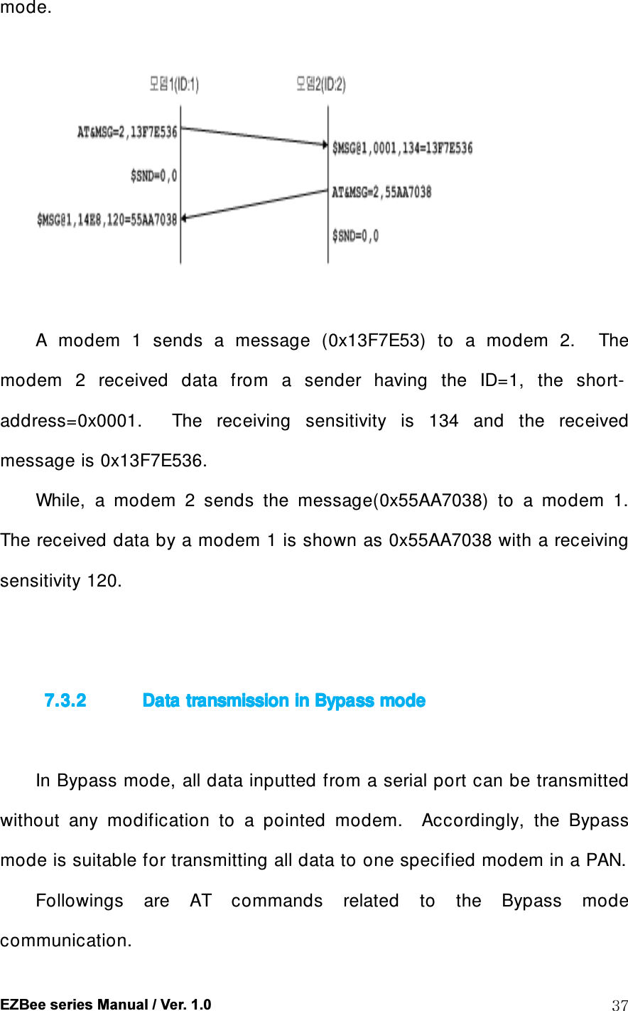
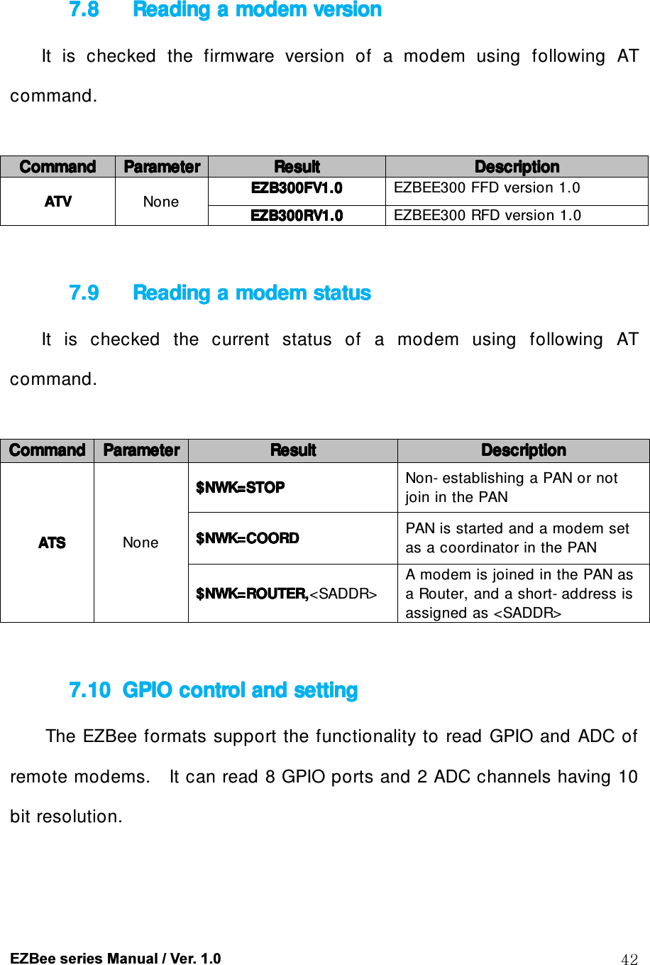
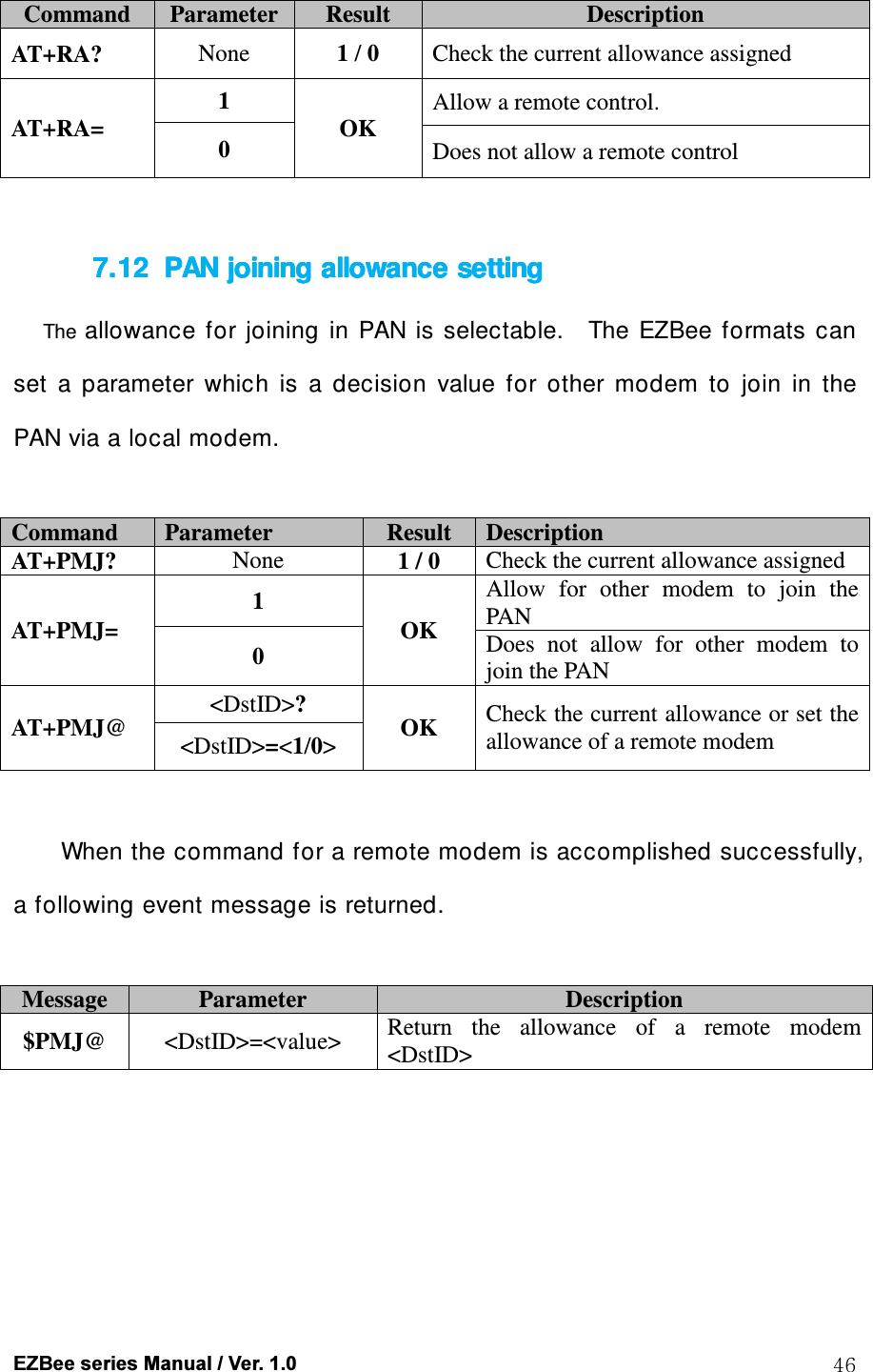
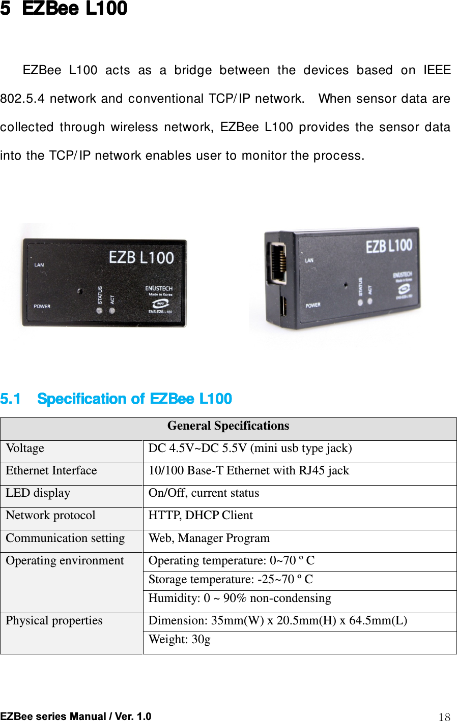
![EZBee series Manual / Ver. 1.0 39 It is not necessary the receiver and sender have been set as same communication mode. The communication mode is selected according to the operating environment. If a sender is set as Bypass mode and a receiver as ASCII mode, and the sender sends a long message, the receiver can receive the message as divided length of messages due to the size of internal buffer or transmission delay. For converting from the Bypass to ASCII mode, a string “ +++” should be typed at least 300 [ msec] later after transmitting the final data. A mode converting is succeeded if no characters are inputted during 300 [ msec] after inputting the string “ +++” . If any characters are inputted within 300 [ msec] , it is considered as the transmitting data.](https://usermanual.wiki/ENUSTECH/EZBL100/User-Guide-1034305-Page-39.png)