ETEK TECHNOLOGY TD5612DCII MODEM User Manual TD 56000III EN
ETEK TECHNOLOGY(SHENZHEN) CO., LTD. MODEM TD 56000III EN
UserManual.wiki
>
ETEK TECHNOLOGY
>
TD5612DCII User Manual
User Manual
Navigation menu
Upload a User Manual
Namespaces
Wiki Guide
HTML
PDF
Info
Views
User Manual
Discussion / Help
Navigation

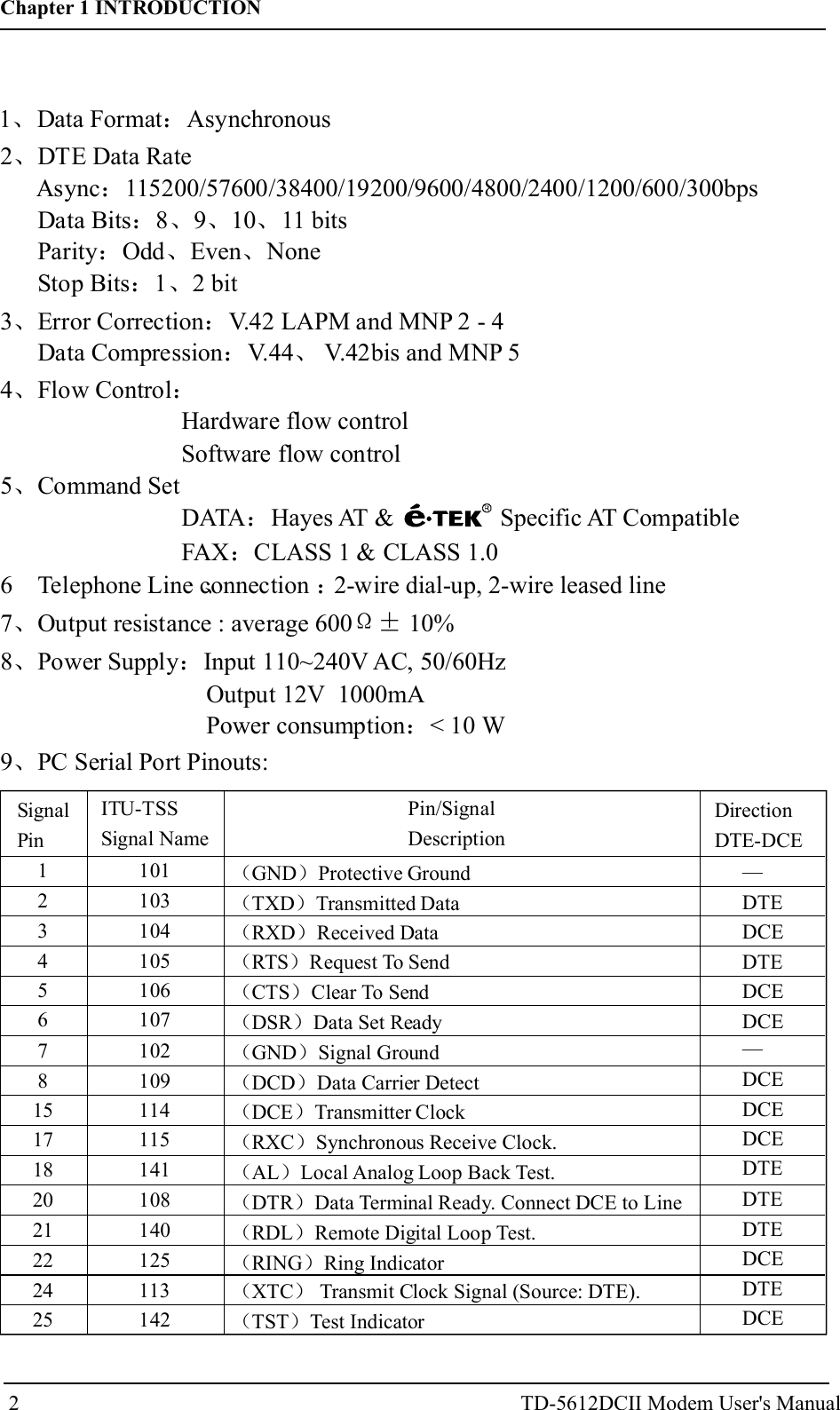
![1Chapter 1 INTRODUCTIONThis chapter describes modem introduction and Features.1. 1 Introductionmodem is a powerful tool which uses a telephone line to link yourcomputer with other computers. Once linked, you can exchange information withdatabases, bulletin boards, and other computer users.is proud to be part of your journey through today's globalcommunications network.1. 2 Modem FeaturesTable 1-1 Data Operation ModesTD-5612DCIIStandard Bit Rate [bps]Bell 103Bell 212V.21V.22V.22 bisV.23V.32V.32bisV.34V.90V.92 upstreamV.92 downstream3001200 Rx/75 Tx or 75 Rx/1200 Tx30012002400 or 120012009600 or 480014400,12000,9600,7200,or 480033600,32100,28800,26400,24000,21600,19200,16800,14400,12000,9600,7200,4800, or 240056000,54667,53333,52000,50667,49333,48000,46667,45333,44000,42667,41333,40000,38667,37333,36000,34667,33333,32000,30667,29333,2800048000,46667,45333,44000,42667,41333,40000,38667,37333,36000,34667,33333,32000,30667,29333,28000,26667,25333,2400056000,54667,53333,52000,50667,49333,48000,46667,45333,44000,42667,41333,40000,38667,37333,36000,34667,33333,32000,30667,29333,28000Chapter 1 INTRODUCTIONTD-5612DCII Modem User's ManualCompatible with BELL 103, 212A standards and ITU V.92 V.90 V.34V.32BIS V.32 V.22BIS V.22 V.21 Bell 212 103 recommendations.The TD-5612DCII modem is a high performance universal modemcapable of transmission speed up to 56Kbps full-duplex on a 2-wire dial-upline. Universal compatibility covers a broad range of ITU-T and BELLstandards.Various operation modes that can be achieved are as follows:、 、 、、 、 、 、 、 ,](https://usermanual.wiki/ETEK-TECHNOLOGY/TD5612DCII/User-Guide-3289680-Page-4.png)
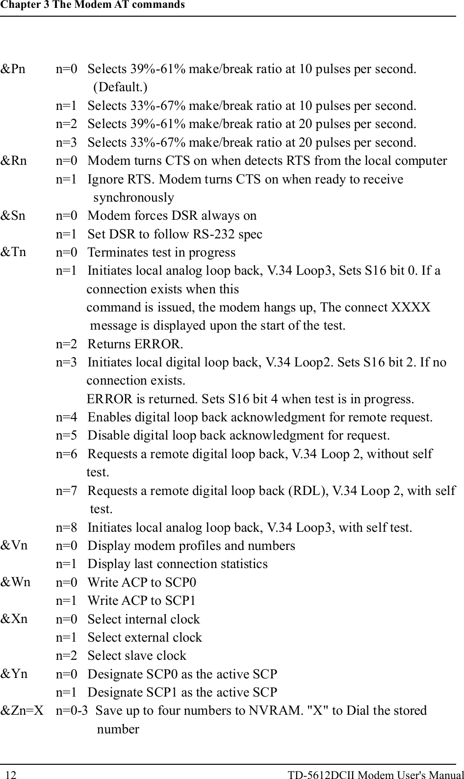
![Note: &X, &Mn: for Sync mode only.+IPR+MSSyntax:Fixed DTE RateSpecifies the DTE-modem interface operation rate in bits/s. Theavailable rates are: 0, 300, 1200, 2400,4800, 9600, 19200, 38400, 57600, 115200bits/sExample: AT+IPR=9600Modulation SelectionThis extended-format compound parameter controls the manner ofoperation of the modulation capabilities in the modem. It accepts sixsubparameters.+MS=[<carrier>[,<automode>[,<min_tx_rate>[,<max_tx_rate>[,<min_rx_rate> [,<max_rx_rate>]]]]]]Where possible <carrier>, <min_tx_rate>, <max_tx_rate>, <min_rx_rate>, and max_rx_rate>values are listed in Table .ModulationBell 103Bell 212V.21V.22V.22 bisV.23V.32V.32bisV.34V.90V.92 upstreamV.92 downstream<carrier>B103B212V21V22V22BV23CV32V32BV34V90V92V92Possible (<min_rx_rate>, <min_rx_rate>, (<min_tx_rate>),and <max_tx_rate>) Rates (bps)3001200 Rx/75 Tx or 75 Rx/1200 Tx30012002400 or 120012009600 or 480014400,12000,9600,7200,or 480033600,32100,28800,26400,24000,21600,19200,16800,14400,12000,9600,7200,4800, or 240056000,54667,53333,52000,50667,49333,48000,46667,45333,44000,42667,41333,40000,38667,37333,36000,34667,33333,32000,30667,29333,2800048000,46667,45333,44000,42667,41333,40000,38667,37333,36000,34667,33333,32000,30667,29333,28000,26667,25333,2400056000,54667,53333,52000,50667,49333,48000,46667,45333,44000,42667,41333,40000,38667,37333,36000,34667,33333,32000,30667,29333,2800013Chapter 3 The Modem AT commandsTD-5612DCII Modem User's Manual](https://usermanual.wiki/ETEK-TECHNOLOGY/TD5612DCII/User-Guide-3289680-Page-16.png)
![Reporting Supported Range of Parameter Values Command: +MS=?Response:+MS: (< carrier> range),(<automode> range),(<min_tx_rate> range),(<max_tx_rate> range), (<min_rx_rate> range), (<max_rx_rate> range)Example :+MS:(B103,B212,V21 ,V22,V22B,V23C,V32,V32B,V34, V90, V92),(0,1),(300-33600),(300-48000),(300-56000),(300-56000)3.4 Error Control/Data Compression Commands+ES - Error Control and Synchronous Mode SelectionThis extended-format command specifies the initial requested mode ofoperation when the modem is operating as the originator, optionally specifiesthe acceptable fallback mode of operation when the modem is operating asthe originator, and optionally specifies the acceptable fallback mode ofoperation when the modem is operating as the answerer. It accepts threenumeric subparameters:Syntax+ES=[<orig_rqst>[,<orig_fbk>[,<ans_fbk>]]]Defined Values<orig_rqst><orig_fbk>Decimal number which specifies the initial requested mode ofoperation when the modem is operating as the originator. The optionsare:0 Initiate call with Direct Mode.1 Initiate call with Normal Mode (also referred to as Buffered Mode)only.2 Initiate V.42 without Detection Phase. If V.8 is in use, disable V.42Detection Phase.3 Initiate V.42 with Detection Phase. (Default.)4 Initiate MNP.6 Initiate V.80 Synchronous Access Mode when connection iscompleted, and Data State is entered. (See +ESA and +ITFcommands.)7 Initiate Frame Tunneling Mode when connection is complete, andData Mode is entered.Decimal number which specifies the acceptable fallback mode ofoperation when the modem is operating as the originator.15Chapter 3 The Modem AT commandsTD-5612DCII Modem User's Manual](https://usermanual.wiki/ETEK-TECHNOLOGY/TD5612DCII/User-Guide-3289680-Page-18.png)
![+EB - Break Handling in Error Control OperationThis extended-format compound parameter controls the break handling inV.42 operation. It accepts three numeric subparameters:Syntax+EB=[<break_selection>[,<timed>[,<default_length>]]]Defined Values<break_selection><timed><default_length>Decimal number 0 specifying that break is to be ignored, i.e.,not signaled to remote DCE.Decimal number 0 specifying that any transmitted V.42 L -SIGNAL will not indicate break signal lengthDecimal number 0 specifying that break is not delivered to theDTE.+ESR - Selective RepeatThis extended-format numeric parameter controls the use of the selectiverepeat (SREJ) option in V.42.Syntax+ESR=[<value>]Decimal number 0 specifying that SREJ is not used.+EFCS - 32-bit Frame Check SequenceThis extended-format numeric parameter controls the use of the 16-bit or32-bit frame check sequence (FCS) option in V.42.Syntax +EFCS=[<value>]Defined Values<value>Decimal number 0 specifying the use of the 16-bit FCS specified in V.42.+ER - Error Control ReportingThis extended-format numeric parameter controls whether or not theextended-format +ER: intermediate result code is transmitted from themodem to the DTE.S95 bit 3 is reset to 0 for +ER=0 and is set to a 1 for +ER=1. The morerecent setting of +ER or S95 bit 3, and the W command setting, determinesthe actual error control result code reporting (see S95 Parameter and WCommand).Syntax+ER=[<value>]Defined Values17Chapter 3 The Modem AT commandsTD-5612DCII Modem User's Manual](https://usermanual.wiki/ETEK-TECHNOLOGY/TD5612DCII/User-Guide-3289680-Page-20.png)
![<value> A decimal number corresponding to the selected error control option:0 =Error control reporting disabled (no +ER intermediate result codetransmitted).1 =Error control reporting enabled (+ER intermediate result codetransmitted).+ETBM - Call Termination Buffer ManagementThis extended-format compound parameter controls the handling of dataremaining in modem buffers upon call termination. It accepts threenumeric subparameters:Syntax+ETBM=[<pending_TD>[,<pending_RD>[,<timer>]]]Defined Values<pending_TD><pending_RD><timer>Decimal number 0 specifying that disconnect will occurimmediately and all buffered transmit data will be discardedwhen the local DTE requests call disconnection.Decimal number 0 specifying that disconnect will occurimmediately and all buffered receive data will be discarded whenthe local DTE requests call disconnection.Decimal number 0 specifying that the modem will not attempt todeliver the buffered data before abandoning the attempt anddiscarding remaining data.\B - Transmit Break to RemoteIn non-error correction mode, the modem will transmit a break signal to theremote modem with a length in multiples of 100 ms according to parameterspecified. If a number in excess of 9 is entered, 9 is used. The commandworks in conjunction with the \K command.Syntax\B<value>Defined Values<value>Decimal number corresponding to the selected option.1-9Break length in 100 ms units. (Default = 3.) (Non-error corrected mode only.)\K - Break ControlControls the response of the modem to a break received from the DTE or theremote modem or the \B command. The parameter value, if valid, is written to S40bits 3, 4, and 5.18Chapter 3 The Modem AT commandsTD-5612DCII Modem User's Manual](https://usermanual.wiki/ETEK-TECHNOLOGY/TD5612DCII/User-Guide-3289680-Page-21.png)
![<value>Decimal number corresponding to the selected option.0 Disables V.42 LAPM to MNP 10 conversion. (Default.)1 Enables V.42 LAPM to MNP 10 conversion.2 Enables V.42 LAPM to MNP 10 conversion; inhibits MNP Extended Servicesinitiation during V.42 LAPM answer mode detection phase.+DS - Data CompressionThis extended-format compound parameter controls the V.42bis datacompression function if provided in the modem. It accepts four numericsubparameters:Syntax+DS=[<direction>[,<compr_neg>[,<max_dict>[,<max_string>]]]] Defined Values<direction><compr_neg><max_dict><max_string>Specifies the desired direction(s) of operation of the datacompression function; from the DTE point of view.0 Negotiated; no compression (V.42bis P0=0).3 both directions, accept any direction (V.42bis P0=11). (Default.)Specifies whether or not the modem should continue to operate ifthe desired result is not obtained.0 Do not disconnect if V.42bis is not negotiated by the remotemodem as specified in <direction>.Specifies the maximum number of dictionary entries (2048 entries)which should be negotiated (may be used by the DTE to limit thecodeword size transmitted, based on its knowledge of the natureof the data to be transmitted).Specifies the maximum string length (32 bytes) to be negotiated(V.42bis P2).+DS44 - V.44 Compression SelectThis extended-format compound parameter controls the V.44 data compressionfunction.Syntax+DS44=[<direction>[,< compress_negotiation >[,<capability>[,<max_codewords_tx> [,<max_codewords_rx>[,<max_string_tx>[,<max_string_rx>[,<max_history_tx> [,<max_history_rx>]]]]]]]]]Defined Values<direction> Decimal number that specifies the desired direction(s) ofoperation of the data compression function; from the DTE pointof view.20Chapter 3 The Modem AT commandsTD-5612DCII Modem User's Manual](https://usermanual.wiki/ETEK-TECHNOLOGY/TD5612DCII/User-Guide-3289680-Page-23.png)
![+DR - Data Compression ReportingThis extended-format numeric parameter controls whether or not theextended-format +DR: intermediate result code is transmitted from themodem to the DTE.S95 bit 5 is reset to 0 for +DR=0 and is set to a 1 for +DR=1. The morerecent setting of +DR or S95 bit 5, and the W command setting, determinesthe actual data compression result code reporting (see S95 Parameter and WCommand).Syntax+DR=[<value>]Defined Values<value> decimal number corresponding to the selected option:0 Data compression reporting disabled (no +DR result codetransmitted).1 Data compression reporting enabled (+DR result code transmitted).(Default.)%C - Enable/Disable Data CompressionEnables or disables data compression negotiation. The modem can onlyperform data compression on an error corrected link. The parameter value, ifvalid, is written to S41 bits 0 and 1.Syntax%C<value>Defined Values<value> Decimal number corresponding to the selected option.0 Disables data compression. Resets S46 bit 1.1 Enables MNP 5 data compression negotiation. Resets S46 bit 1.2 Enables V.42 bis data compression. Sets S46 bit 1.3 Enables both V.42 bis and MNP 5 data compression. Sets S46 bit 1.(Default.)22Chapter 3 The Modem AT commandsTD-5612DCII Modem User's Manual](https://usermanual.wiki/ETEK-TECHNOLOGY/TD5612DCII/User-Guide-3289680-Page-25.png)