EVERBEST MACHINERY INDUSTRY DT-989 Digital Multimeter User Manual
SHENZHEN EVERBEST MACHINERY INDUSTRY CO.,LTD. Digital Multimeter Users Manual
UserManual.wiki
>
EVERBEST MACHINERY INDUSTRY
>
DT 989 User Manual
User manual.pdf
Navigation menu
Upload a User Manual
Namespaces
Wiki Guide
HTML
PDF
Info
Views
User Manual
Discussion / Help
Navigation

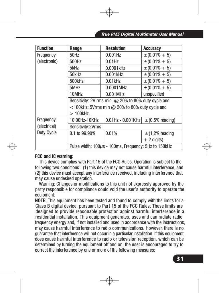
![29True RMS Digital Multimeter User Manual8. SpecificationsRange500mV5V50V500V1000VResolution0.01mV0.0001V0.001V0.01V0.1V50/60HZ±0.5%+5ACVoltage<1KHZ±1.0%+5±1.5%+10<5kHZ±3.0%+5±3.5%+10unspecified<20KHZ[1]±5.5%+20unspecifiedunspecifiedRange500mV[1]5V50V500V1000VResolution0.01mV0.0001V0.001V0.01V0.1VAccuracy(0.1% + 5digits)(0.05% + 5digits)(0.05% + 5digits)(0.05% + 5digits)(0.1% + 5)DC Voltage[1] When using the relative mode (REL Q) to compensate for offsets.FunctionRange500 [1]5k50k500k5M50MΩΩΩΩΩΩResolution0.010.0001k0.001k0.01k0.0001M0.001MΩΩΩΩΩΩAccuracy0.20%+100.20%+50.20%+50.50%+50.50%+52.0%+10FunctionResistance[1] When using the relative mode (REL Q) to compensate for offsets.5V50V500V1000V0.0001V0.001V0.01V0.1V<1KHZ(1.2% + 20)(AC+DC) <5KHZ(3.0% + 20)[1] upper 10 % of range,](https://usermanual.wiki/EVERBEST-MACHINERY-INDUSTRY/DT-989/User-Guide-2858098-Page-29.png)
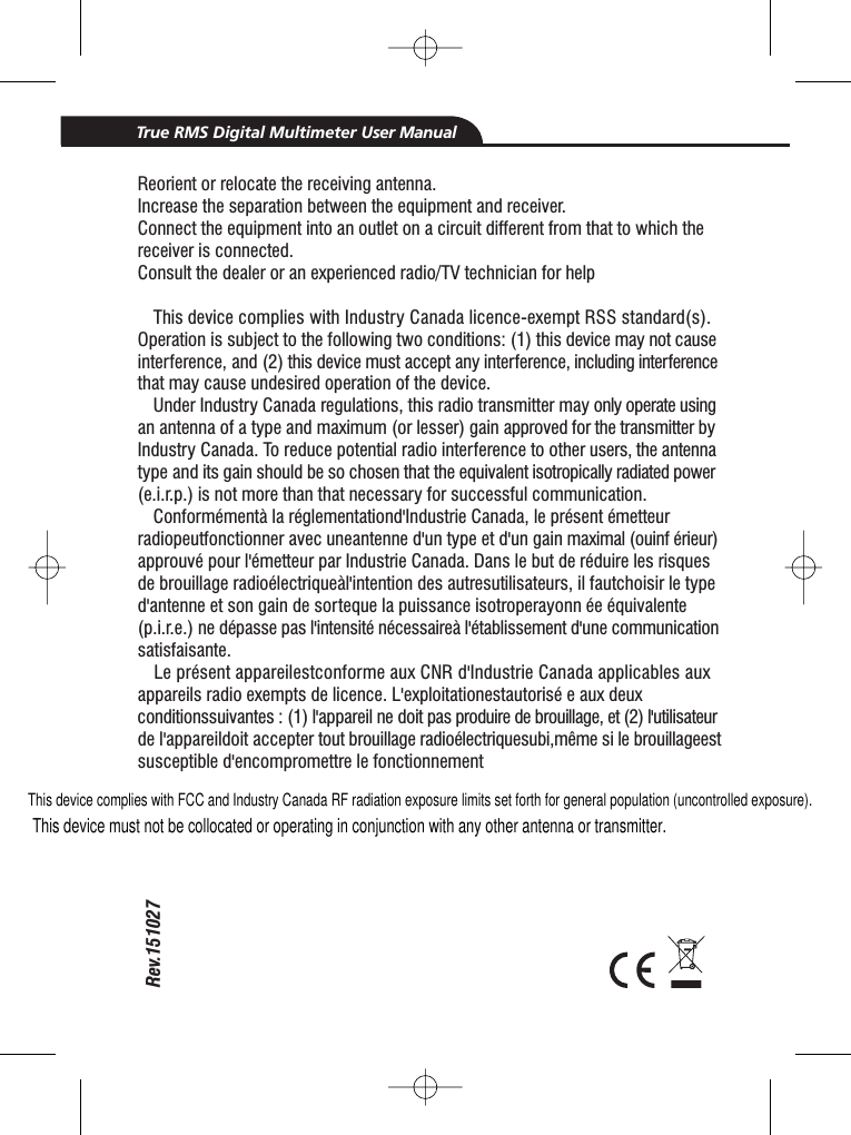
![30True RMS Digital Multimeter User ManualRange-200 to 1350˚C1. Does not include error of the thermocouple probe.2. Accuracy specification assumes ambient temperaturestable to ±1˚C.3. Use a long time, reading will increase 2 ˚C.500μA5000μA50mA500mA10A500μA5000μA50mA500mA10A(20A: 30 sec max with reduced accuracy)All AC current ranges are specified from 5% of range to100% of range5nF[1]50nF500nF5μF50μF500μF10mF[1] With a film capacitor or better, using relative mode(REL ) to zero residual.ΔResolution0.1˚C0.01 A0.1 A0.001mA0.01mA0.001A0.01 A0.1 A0.001mA0.01mA0.001A0.001nF0.01nF0.1nF0.001 F0.01 F0.1 F0.01mFμμμμμμμAccuracy±(1.0% reading + 3.0°C)±(1.0% reading +5.4°F)(probe accuracy not included)±0.2%+5±0.2%+5±0.2%+5±0.3%+8±0.5%+8<1KHZ±(0.8% + 5)±(1.5% + 20)±(1.5% + 8)±(1.0% + 8)±(1.5% + 8)±(1.0% + 8)±(1.5% + 8)±(2.5% + 20)FunctionTemp(type-K)DC CurrentAC CurrentCapacitance<5KHZ±(3% + 5)](https://usermanual.wiki/EVERBEST-MACHINERY-INDUSTRY/DT-989/User-Guide-2858098-Page-30.png)