Electronic Systems Technology ESTEEM195EP BASE STATION TRANSMITTER User Manual CHAPTER 2
Electronic Systems Technology BASE STATION TRANSMITTER CHAPTER 2
Contents
- 1. FCC INFORMATION
- 2. SPECIFICATIONS
- 3. INTERFACE PORTS
- 4. RADIO CONFIGURATION
- 5. SECURITY
- 6. TROUBLESHOOTING
- 7. QUICK START GUIDE 1
- 8. FRONT COVER
- 9. TABLE OF CONTENTS
- 10. INTRODUCTION
- 11. CONFIGURATION DIAGRAMS
- 12. STARTING OUT
- 13. WEB CONFIGURATION MANAGER
- 14. EXAMPLE CONFIGURATIONS 1
- 15. EXAMPLE CONFIGURATIONS 2
- 16. REPEATING FIGURES
- 17. ANTENNA SETUP
- 18. QUICK START GUIDE 2
- 19. QUICK START GUIDE 3
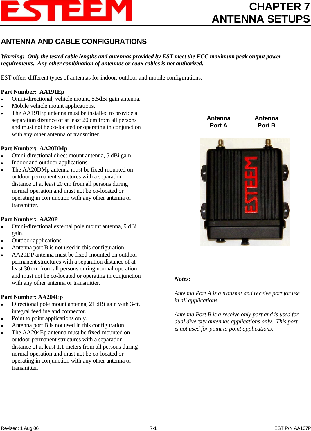
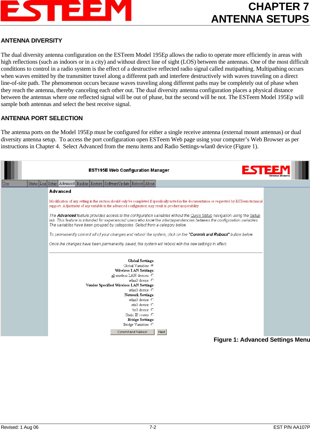
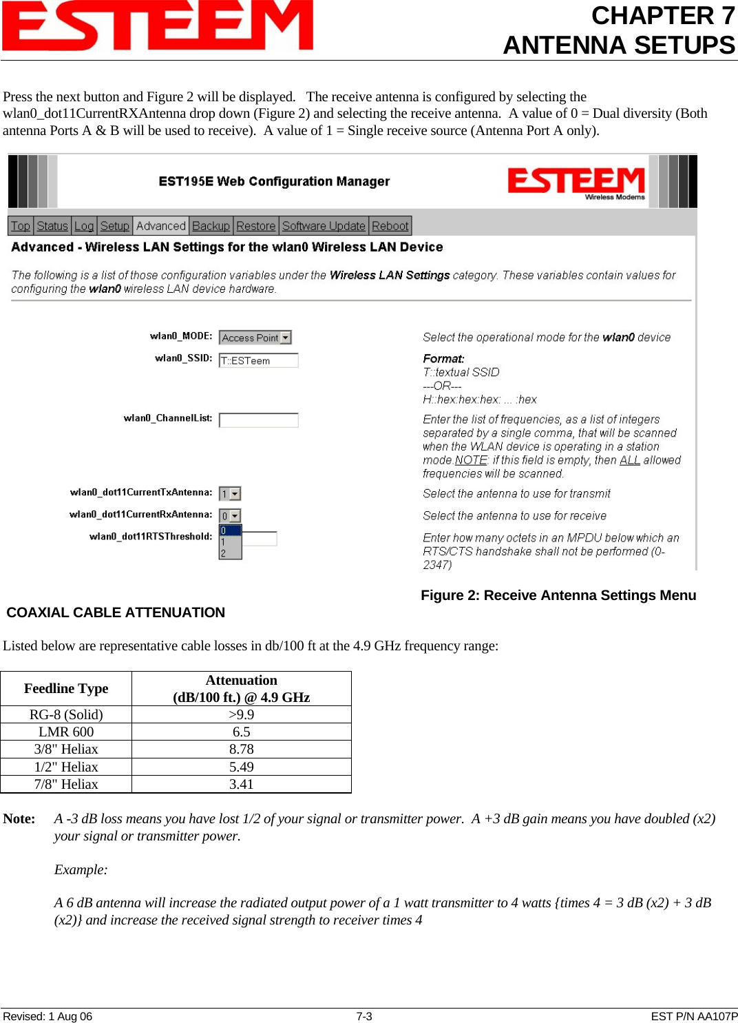
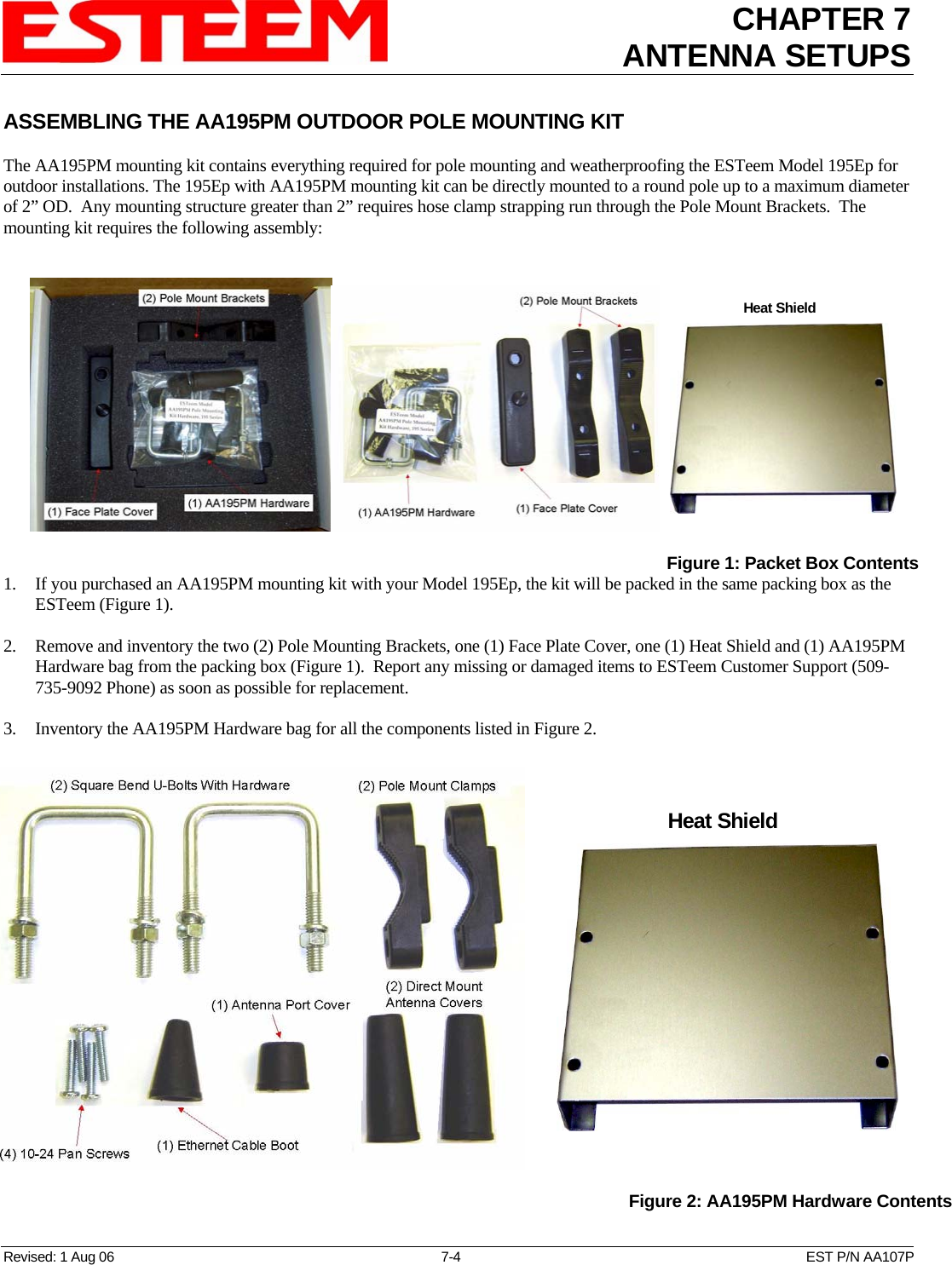
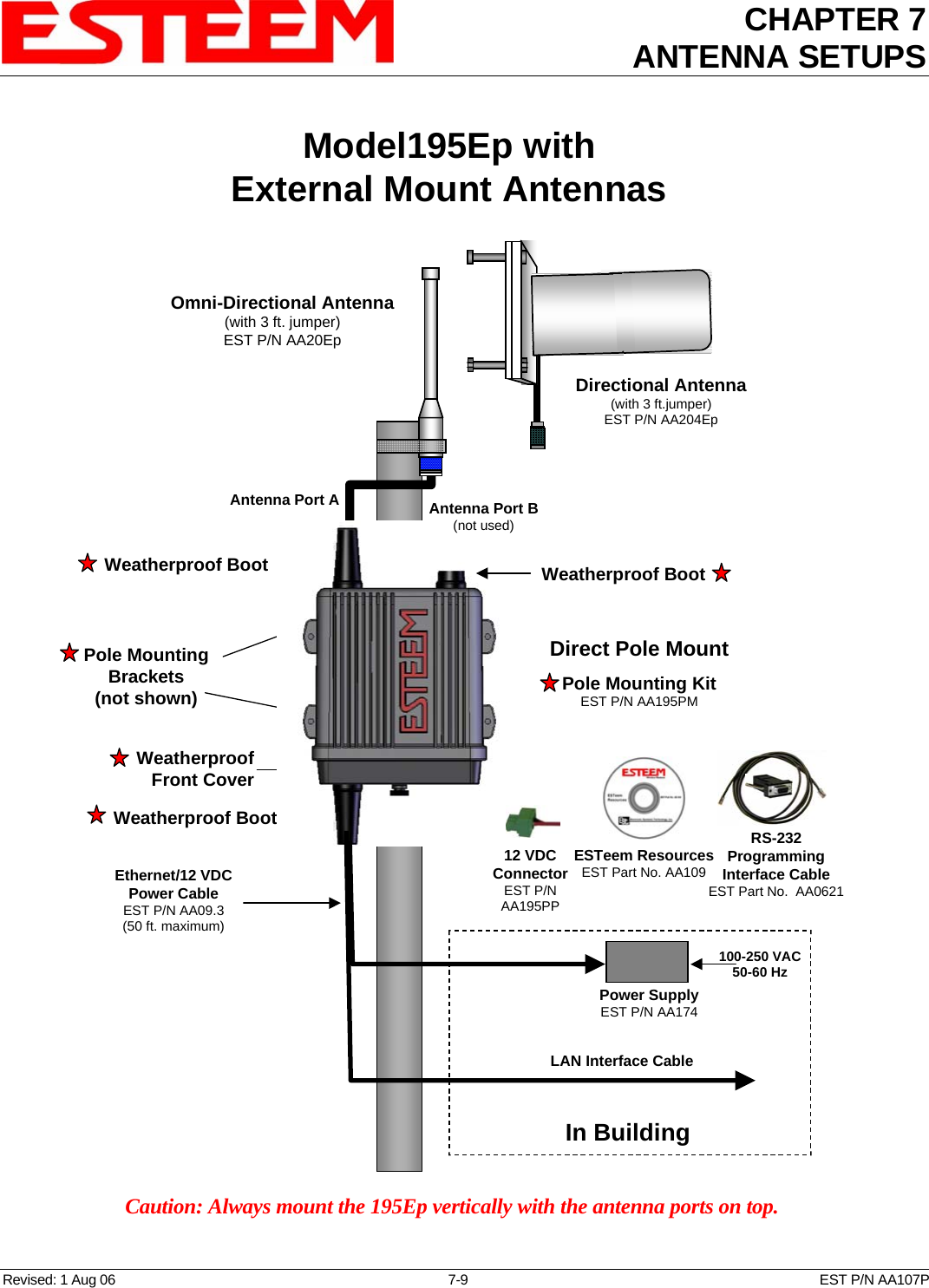
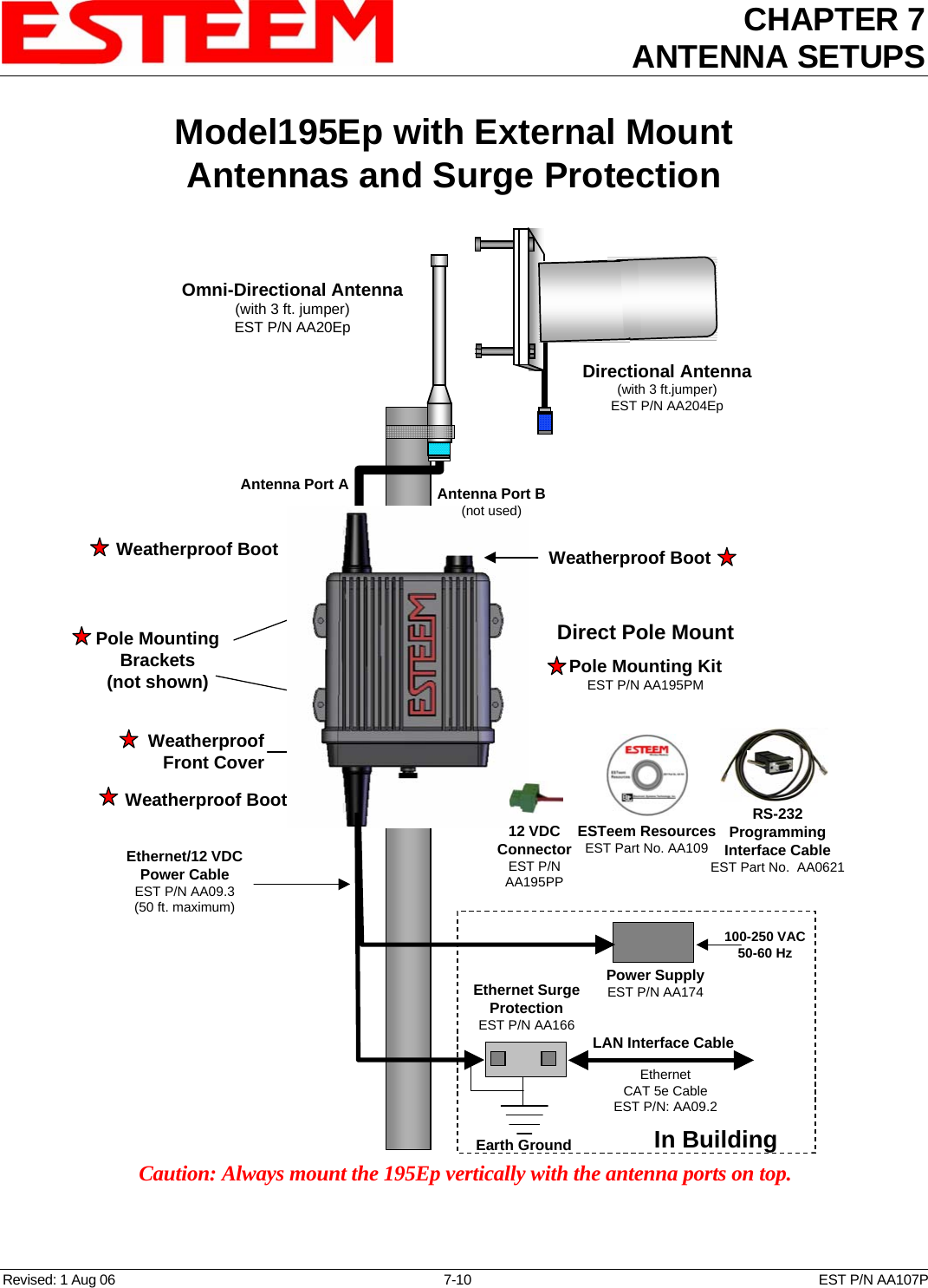
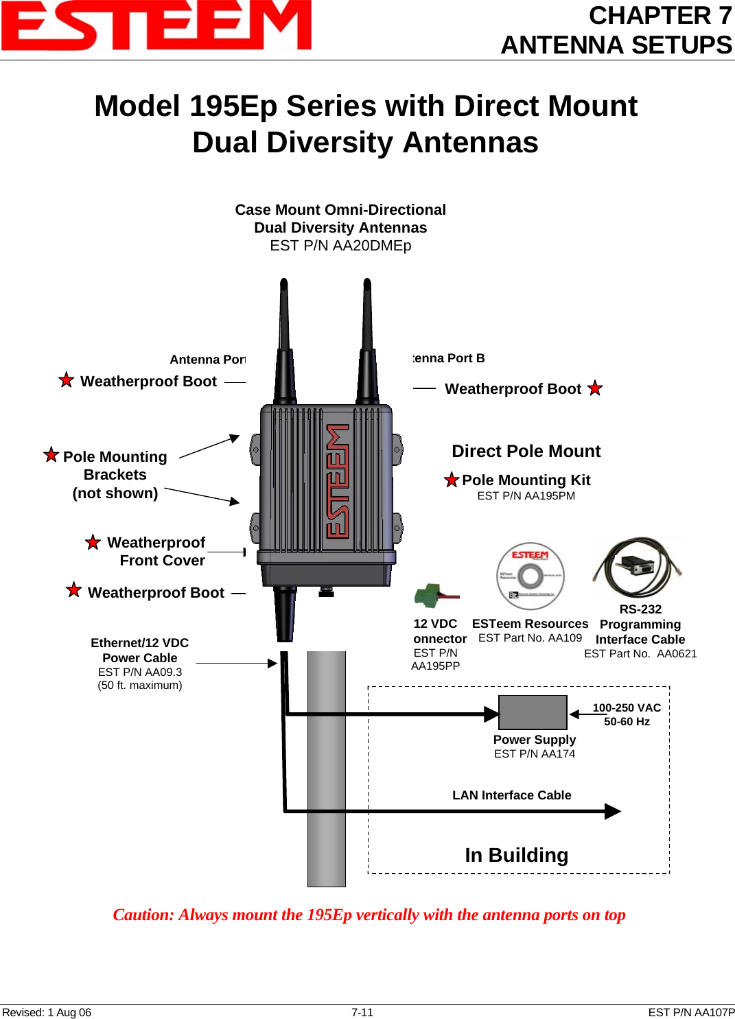
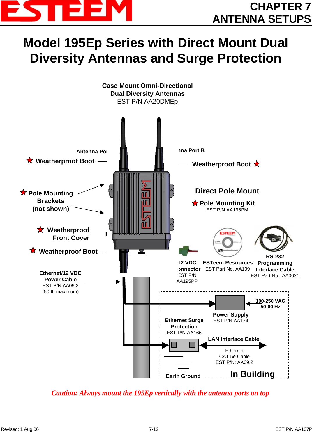
ANTENNA SETUP
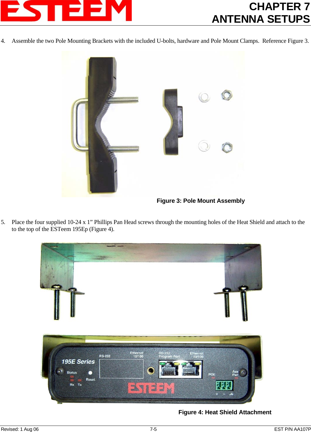
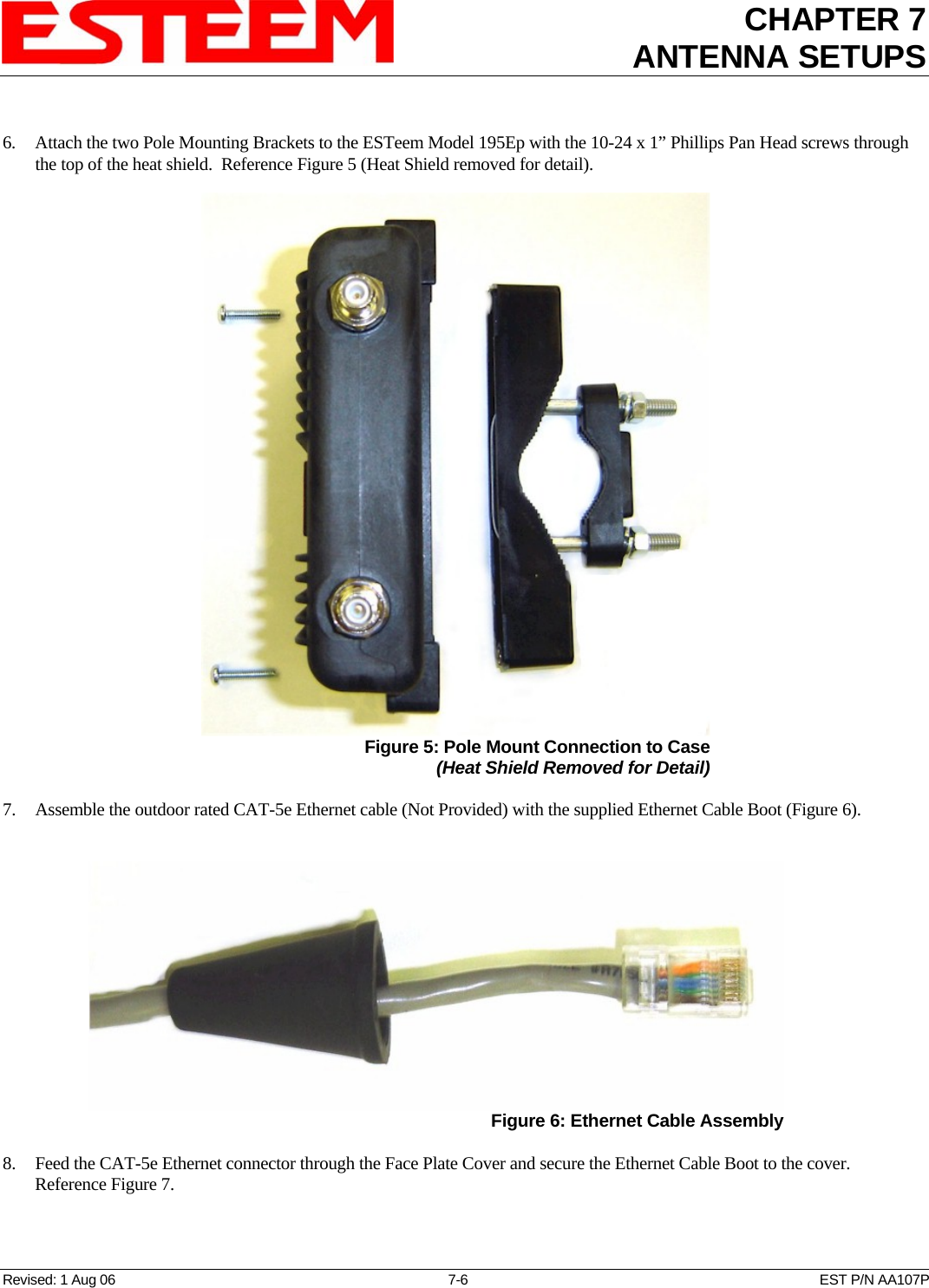
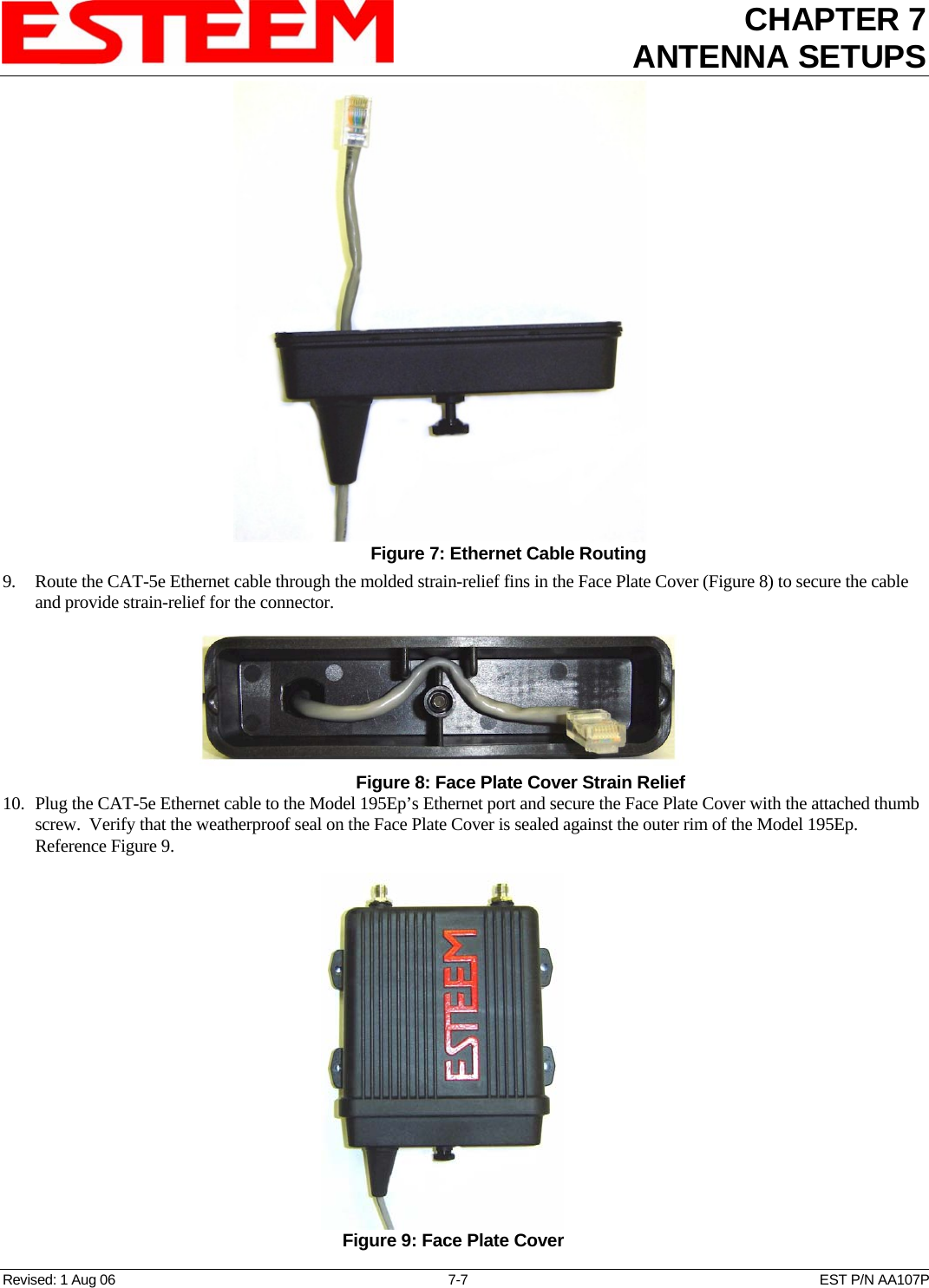
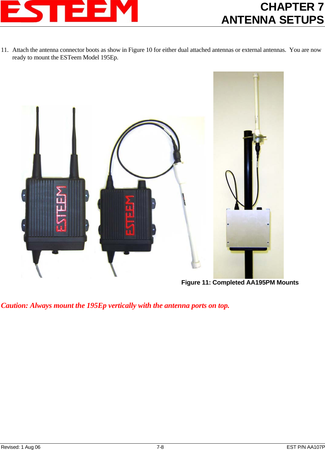
![CHAPTER 7 ANTENNA SETUPS Revised: 1 Aug 06 7-13 EST P/N AA107P FRESNEL ZONE The Fresnel zone shows the ellipsoid spread of the radio waves around the visual line-of-sight after they leave the antenna (see figure above). This area must be clear of obstructions or the signal strength will be reduced due to signal blockage. Typically, 20% Fresnel Zone blockage introduces little signal loss to the link. Beyond 40% blockage, signal loss will become significant. This calculation is based on a flat earth. It does not take into account the curvature of the earth. It is recommended for RF path links greater than 7 miles to have a microwave path analysis done that takes the curvature of the earth and the topography of the terrain into account. Fresnel Zone Radius = 72.1 SQRT [(d1d2) / (F(d1 + d2)] Units Fresnel Zone Radius in feet. d1 and d2 in statue miles F in GHz](https://usermanual.wiki/Electronic-Systems-Technology/ESTEEM195EP.ANTENNA-SETUP/User-Guide-690222-Page-13.png)