EnergyICT NV RTUS2-WC DATA CONCENTRATOR COLLECTING METER DATA OVER WAENIS RF NETWORK User Manual EMNL000057 01 EN EVOGate 2 0
EnergyICT NV DATA CONCENTRATOR COLLECTING METER DATA OVER WAENIS RF NETWORK EMNL000057 01 EN EVOGate 2 0
UserManual.wiki
>
EnergyICT NV
>
RTUS2 WC User Manual
USERS MANUAL
Navigation menu
Upload a User Manual
Namespaces
Wiki Guide
HTML
PDF
Info
Views
User Manual
Discussion / Help
Navigation
![6 / 29 Chapter 1: Introduction Introduction This chapter provides the user with an introduction to the EVOGate 2.0, its main internal components (including EnergyICT’s RTU+ Server2 data concentrator) and its main functions. Chapter description This chapter describes the following topics: Topic Page About the EVOGate 2.0 [7] EVOGate 2.0 Component Overview [8] Technical Specifications [10] RTU+Server2 Casing [11] IP Enclosure Casing [12] RTU+Server2 Labels [14] IP Enclosure Labels [16] LED Indications [18]](https://usermanual.wiki/EnergyICT-NV/RTUS2-WC/User-Guide-1590008-Page-6.png)
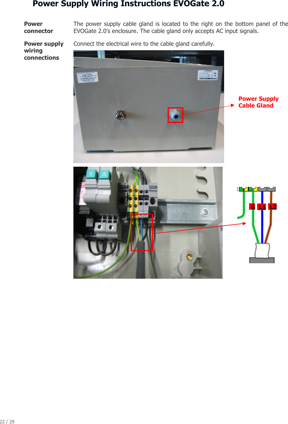
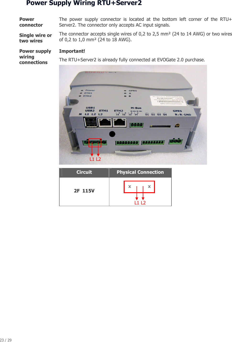
![20 / 29 Chapter 2: Mounting and Wiring Introduction This chapter provides information on the physical installation of the polyester enclosure, including mounting and wiring instructions. Chapter description This chapter describes the following topics: Topic Page Mounting Instructions IP Enclosure [20] Power Supply Wiring Safety Guidelines [20] Power Supply Wiring Instructions EVOGate 2.0 [21] Power Supply Wiring RTU+Server2 [22]](https://usermanual.wiki/EnergyICT-NV/RTUS2-WC/User-Guide-1590008-Page-20.png)
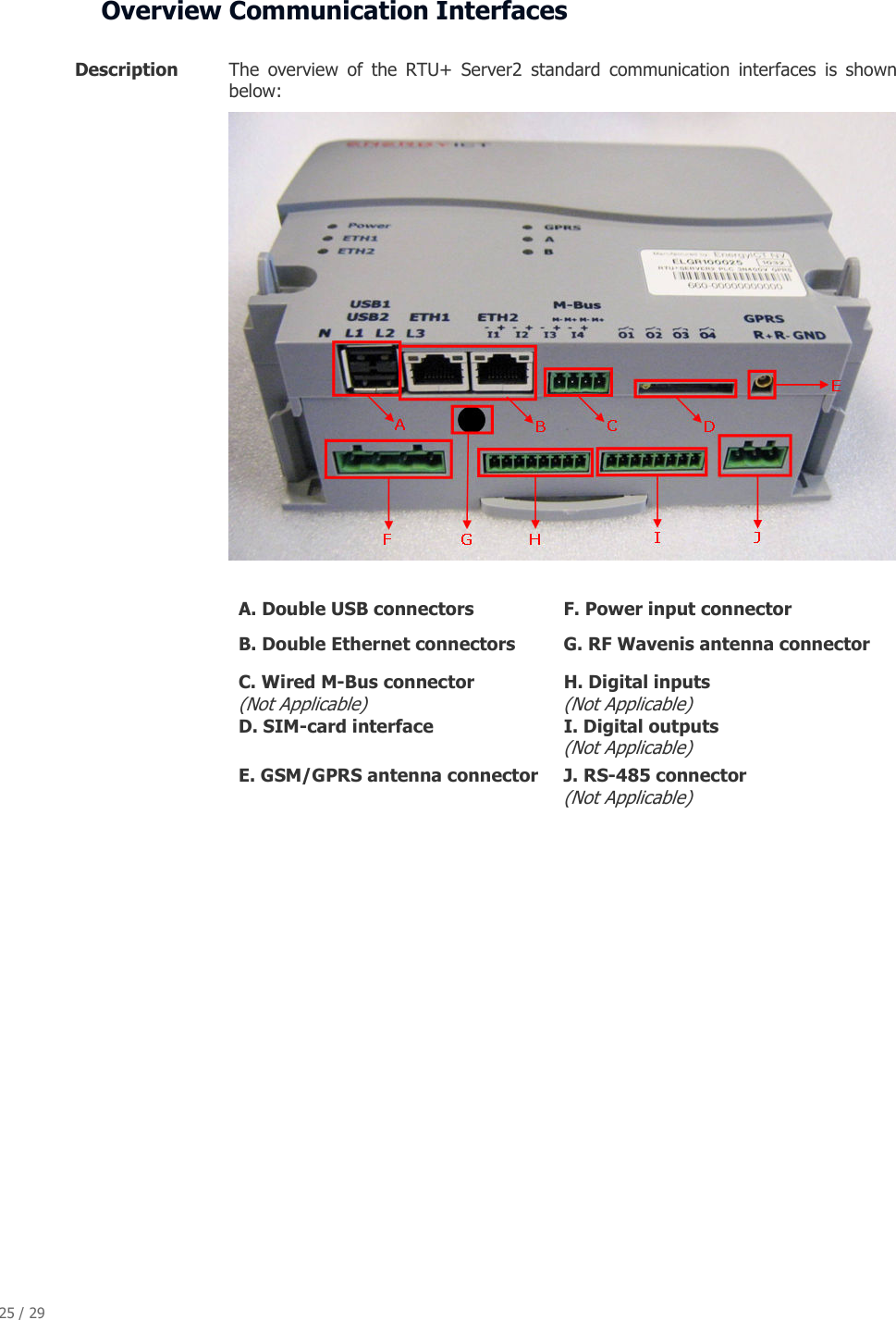
![24 / 29 Chapter 3: Communication Interfaces Introduction The EnergyICT RTU+ Server2 is configured with a number of communication interfaces for downstream communication to the meters as well as upstream communication to a central data management system. Chapter description This chapter contains information on the communication cards of the RTU+Server2. Important! All communication interfaces are already in place at purchase; installation and maintenance may only be carried out by qualified personnel. Topic Page Overview Communication Interfaces [24] Upstream Double Ethernet Connection [25] Double USB 2.0 Interface [25] GSM/GPRS Modem [26] Downstream Wavenis RF Modem [27]](https://usermanual.wiki/EnergyICT-NV/RTUS2-WC/User-Guide-1590008-Page-24.png)