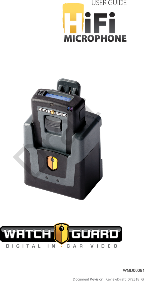
Enforcement Video TRN410 MIC-WRL-TRN-410 User Manual High Fidelity Microphone User Guide

Enforcement Video, LLC (d.b.a. WatchGuard Video) MIC-WRL-TRN-410 High Fidelity Microphone User Guide

User Manual

Document Revision: ReviewDraft_072318_GDraft
Important NoticeCopyright © 2018 WatchGuard, Inc. All rights reserved. This documentand supporting data are the exclusive property of WatchGuard, Inc. andmay not be copied and/or reproduced without permission.Software and firmware updatesWatchGuard is committed to the continual testing and improvement ofour software and firmware. As new revisions become available, theseupdates will be made available to your agency; fees may apply dependingon your licensing agreement.Contact informationWatchGuard, Inc.415 East Exchange ParkwayAllen, Texas 75002Customer Service: 1-800-605-6734Customer Service web portal:https://support.watchguardvideo.com/hc/en-usSend us your suggestionsTell us about your experience and how you are using the HiFiMicrophone. We will do our best to accommodate any suggestions youmay have in future revisions.U.S. customers, call Customer Service or submit a ticket through theCustomer Service web portal. International customers, contact your localdistributor or submit a ticket through the Customer Service web portal.Trademark noticesAll marks, names, and logos mentioned herein are the property of theirrespective owners.iiWGD00091Revision ReviewDraft_072318_GDraft
FCC and IC noticesThis equipment complies with Part 15 of the FCC rules and IndustryCanada licence-exempt RSS standard(s). This equipment should only beused with the antenna supplied by WatchGuard. Any changes ormodifications not expressly approved by the manufacturer could void theuser's authority to operate the equipment.Cet appareil est conforme à la Partie 15 des règlements de la FCC etIndustrie Canada exempts de licence standard RSS. Cet appareil doit êtreutilisé uniquement avec l'antenne fournie par WatchGuard. Toutchangement ou modification non expressément approuvée par lefabricant pourrait annuler l'autorité de l'utilisateur de faire fonctionnerl'appareil.This device complies with Part 15 of the FCC rules and Industry Canadalicence-exempt RSS standard(s) subject to the following two conditions:1. This device may not cause harmful interference.2. This device must accept all interference received, including interferencethat may cause undesired operation.Cet appareil est conforme à la Partie 15 des règlements de la FCC etIndustrie Canada exempts de licence standard RSS soumis aux deuxconditions suivantes:1. Cet appareil ne peut causer des interférences nuisibles.2. Cet appareil doit accepter toutes les interférences reçues, y compris lesinterférences qui peuvent perturber le fonctionnement.Under Industry Canada regulations, this radio transmitter may onlyoperate using an antenna of a type and maximum (or lesser) gainapproved for the transmitter by Industry Canada. To reduce potentialradio interference to other users, the antenna type and its gain should beso chosen that the equivalent isotropically radiated power (e.i.r.p.) is notmore than that necessary for successful communication.Conformément à la réglementation d'Industrie Canada, cet émetteur radione peut fonctionner à l'aide d'une antenne d'un type et maximum (oumoins) Gain approuvé pour l'émetteur par Industrie Canada. Pour réduirele risque d'interférence avec d'autres utilisateurs, le type d'antenne etson gain doivent être choisis afin que la puissance isotrope rayonnéeéquivalente (PIRE) ne dépasse pas ce qui est nécessaire pour unecommunication réussie.The radio transmitter IC:9073A-TRN410 and the base IC:9073A-CHG410have been approved by Industry Canada to operate with the antennatypes listed below with the maximum permissible gain and requiredantenna impedance for each antenna type indicated. Antenna types notiiiWGD00091Revision ReviewDraft_072318_GDraft
included in this list, having a gain greater than the maximum gainindicated for that type, are strictly prohibited for use with this device.lAntenna type (radio transmitter): WatchGuard Video part numberWGP01589 unity gain (0dBi), 50 Ohm impedancelAntenna type (base): WatchGuard Video part number WGP01573 unitygain (0 dBi), 50 ohm impedanceCet émetteur radio IC:9073A-TRN410 et la base IC:9073A-CHG410 ontété approuvés par Industrie Canada pour fonctionner avec les typesd'antennes énumérés ci-dessous avec le gain maximal admissible etl'impédance d'antenne requise pour chaque type d'antenne indiqué.Types d'antennes ne figurent pas dans cette liste, ayant un gainsupérieur au gain maximum indiqué pour ce type, sont strictementinterdites pour une utilisation avec cet appareil.lType d'antenne (émetteur radio): WatchGuard Video part numberWGP01589 unity gain (0dBi), 50 Ohm impedancelType d'antenne (base): WatchGuard Video part number WGP01573 unitygain (0 dBi), 50 Ohm impedanceThe antennas used for this transmitter must be installed to provide aseparation distance of at least 20 cm from all persons and must not beco-located or operating in conjunction with any other antenna ortransmitter.Les antennes pour cet émetteur doivent être installées en assurant unedistance d'au moins 20 cm de toute personne et ne doivent pas êtresituées à proximité ni utilisées en conjonction d'autre antenne ouémetteur.This device complies with Health Canada’s Safety Code. The installer ofthis device should ensure that RF radiation is not emitted in excess of theHealth Canada’s requirement. Information can be obtained athttp://www.hc-sc.gc.ca/ewh-semt/pubs/radiation/radio_guide-lignes_direct/index-eng.phpCet appareil est conforme avec Santé Canada Code de sécurité 6. Leprogramme d’installation de cet appareil doit s’assurer que lesrayonnements RF n’est pas émis au-delà de l’exigence de Santé Canada.Les informations peuvent être obtenues: http://www.hc-sc.gc.ca/ewh-semt/pubs/radiation/radio_guide-lignes_direct/index-eng.phpivWGD00091Revision ReviewDraft_072318_GDraft
ContentsContentsIntroduction 7Welcome 8About this Document 8Related documents and information 8About the HiFi Microphone 9Technical specifications 10Warranty Information 10HiFi Microphone 15Overview 16Using the HiFi Microphone 17Beginning a shift 17During a shift 17Ending a shift 17Base 18Status LEDs 19DVR cable connection 20Antenna connection 20Contacts for charging and synchronizing 21Transmitter 21Talk/Mute slide button 22Display 23Display backlight button 23Mode button 23Status LEDs 24Power switch 25WGD00091Revision ReviewDraft_072318_GvDraft
ContentsContacts for charging and synchronizing 25External microphone jack 26Display 26Status icons 27Mode icons 28Synchronizing the Transmitter and the Base 29Charging the Transmitter 30Charging in a vehicle with the ignition off 31Using Two HiFi Microphones 31Best Practices and Troubleshooting 33Best Practices 34Installation best practices 34Usage best practices 34Troubleshooting 35If you have no reception... 35If you have poor reception, static, or noise... 35If the transmitter does not respond to or synchronize with thebase... 36Index 37viWGD00091Revision ReviewDraft_072318_GDraft
IntroductionIntroductionIn this section...lWelcome (page 8)lAbout this document (page 8)lRelated documents and information (page 8)lAbout the HiFi Microphone (HiFi Mic) (page 9)lTechnical specifications (page 10)lWarranty information (page 10)WGD00091Revision ReviewDraft_072318_G7Draft
IntroductionWelcomeWelcome to the WatchGuard HiFi Microphone User Guide. This guide isdesigned to walk you through the basics of using your HiFi Microphones(HiFi Mics) to help your WatchGuard 4RE DVRs collect quality audioevidence.About this DocumentThe HiFi Microphone User Guide covers the basic parts of the HiFi Mic aswell as its most common functions including:lSynchronizing the transmitter (mic) and the base so the DVR can recordaudiolCharging the miclTriggering a recorded event from the miclPutting the mic into Covert modelSetting up the mic to notify you when it has a change to its statusNote: This user guide covers the basic use of the HiFiMic. It is not a comprehensive manual for every possibleaction or situation you could experience with the HiFi Mic.If you have a question about the HiFi Mic that is notcovered in the user guide, contact your WatchGuardrepresentative.Related documents and informationFor subjects related to the WatchGuard 4RE system that are not coveredby the HiFi Microphone User Guide, see the following documents:l4RE In-Car DVR Quick Start Guidel4RE In-Car DVR Installation Posterl4RE In-Car DVR User Guide8WGD00091Revision ReviewDraft_072318_GDraft
About the HiFi MicrophoneAbout the HiFi MicrophoneThe HiFi Microphone (HiFi Mic) is one of the WatchGuard components fortransmitting audio to the 4RE DVR (digital video recorder) during thevideo recording process.The HiFi Mic consists of two parts:lBase: The base is the part of the HiFi Mic that is mounted in the vehicleand physically connects to the DVR and the antenna.lTransmitter (mic): The mic is the part of the HiFi Mic that you attach toyour apparel or duty belt.The HiFi Mic performs the following major functions:lTransmits audiolSynchronizes the mic and the base so the DVR can record transmittedaudiolCharges the miclTriggers a recorded eventlDisables all mic lights and sounds for Covert modelNotifies you when it has a change in its statusWGD00091Revision ReviewDraft_072318_G9Draft
IntroductionTechnical specificationsThe following table lists the technical specifications for the HiFi Mic:OperatingvoltageTransmitter: 4.2 VDCBase: 12 VDCFrequency 900 MHz (902 – 928 MHz) – 52 channels, digital spreadspectrumOperatingrangeOver 1 mile in open line of sightImportant! Operatingrange differs according tothe environment.Jacks Transmitter: Lapel microphone jackBase: 8-pin RJ-45 for power, audio out, and trigger outBattery Capacity: Lithium-ion 4.2 VDC/1200mAhCharging time: 3 hoursStand-by time: 25 daysTalk time: 8-12 hoursNote: Performance candegrade as the battery ages.Warranty InformationWatchGuard, Inc., in recognition of its responsibility to provide qualitysystems, components, and workmanship, warrants each system, part,and component it manufactures first sold to an end user to be free fromdefects in material and workmanship for a period of one-year from thedate of purchase. A defective component that is repaired or replacedunder this limited warranty will be covered for the remainder of theoriginal warranty period. Where defects in material or workmanship mayoccur, the following warranty terms and conditions apply:10WGD00091Revision ReviewDraft_072318_GDraft
Warranty InformationWarrantorThis warranty is granted by WatchGuard, Inc., 415 East ExchangeParkway, Allen, TX 75002, Telephone: 1-800-605-6734.Parties to whom warranty is intendedThis warranty extends to the original end user of the equipment only andis not transferable. Any exceptions must be approved in writing fromWatchGuard, Inc..Parts and components coveredAll parts and components and repair labor of the warranted unitmanufactured and/or installed by WatchGuard, Inc. are covered by thiswarranty, except those parts and components excluded below.Parts and components not coveredThe limited warranty excludes normal wear-and-tear items such asfrayed or broken cords, broken connectors, scratched or broken displaysor consumable items such as batteries. WatchGuard, Inc. reserves theright to charge for damages resulting from abuse, improper installation,or extraordinary environmental damage (including damages caused byspilled liquids) to the unit during the warranty period at rates normallycharged for repairing such units not covered under the limited warranty.In cases where potential charges would be incurred due to saiddamages, the agency submitting the system for repairs will be notified.Altered, damaged, or removed serial numbers results in voiding thislimited warranty. If while under the warranty period, it is determined thatthe WatchGuard, Inc. system was internally changed, modified, or repairattempted, the system warranty will become null and void.Limited liabilityWatchGuard, Inc.’s liability is limited to the repair or replacement ofcomponents found to be defective by WatchGuard, Inc. WatchGuard,Inc. will not be liable for any direct, indirect, consequential, or incidentaldamages arising out of the use of or inability to use the system even if theunit proved to be defective. WatchGuard, Inc. will not be responsible forany removal or re-installation cost of the unit or for damages caused byimproper installation.WGD00091Revision ReviewDraft_072318_G11Draft
IntroductionRemedyIf, within the duration of this warranty, a unit or component covered bythis warranty is returned to WatchGuard, Inc. and proves to be defectivein material or workmanship, WatchGuard, Inc. shall (at its option) repairor replace any defective components or offer a full refund of the purchaseprice. Replacement of a defective component(s) pursuant to thiswarranty shall be warranted for the remainder of the warranty periodapplicable to the system warranty period.ShippingDuring the first ninety (90) days of the initial warranty period,WatchGuard, Inc. will provide a prepaid shipping label to return anydefective unit for end users in the continental United States providedserial numbers are submitted with the request. In such event, contactWatchGuard, Inc.’s Customer Service Department to request a returnmaterial authorization (RMA) number. Failure to obtain and use aWatchGuard, Inc. prepaid shipping label in the first ninety days (90) onthe return shipment will result in the end user being responsible forshipping costs to WatchGuard, Inc. After the first ninety (90) days, theend user will be responsible for any shipping charges to WatchGuard,Inc. WatchGuard, Inc. will return ship the product to a customer withinthe continental United States by prepaid ground shipping only. Anyexpedited shipping costs are the responsibility of the end user.Customers that are outside the continental United States will beresponsible for all transportation costs both to and from WatchGuard,Inc.’s factory for warranty service, including without limitation to anyexport or import fees, duties, tariffs, or any other related fees that maybe incurred during transportation.You may also obtain warranty service by contacting your localWatchGuard, Inc. Authorized Service Center (ASC) for shippinginstructions. A list of local ASCs may be obtained by contactingWatchGuard, Inc.’s Customer Service Department. Customers will beresponsible for all transportation costs to and from the local ASC forwarranty service.Extended warrantyExtended warranties may be purchased directly from WatchGuard, Inc.Any and all extended warranties must be purchased prior to theexpiration of any previous warranty. Failure to purchase an extendedwarranty prior to the expiration of the warranty period will require thecovered unit to be physically inspected at the facility of the manufacturerand any repairs necessary to bring the unit back to full working ordermust be performed prior to the issuance of any new warranty. The12WGD00091Revision ReviewDraft_072318_GDraft
Warranty Informationcustomer will be responsible for the cost of the inspection (equal to 1hour of labor) plus the standard costs associated with any requiredrepairs. Should you have any further questions regarding theWatchGuard, Inc. limited warranty, please direct them to:WatchGuard, Inc.Attn: Customer Service Department415 East Exchange ParkwayAllen, Texas 750021-800-605-6734https://support.watchguardvideo.com/hc/en-uswww.watchguardvideo.comWGD00091Revision ReviewDraft_072318_G13Draft
14WGD00091Revision ReviewDraft_072318_GIntroductionThis page intentionally left blank.Draft
HiFi MicrophoneHiFi MicrophoneIn this section...lHiFi Microphone (HiFi Mic) overview (page 16)lUsing the HiFi Mic (page 17)lBase features (page 18)lTransmitter features (page 21)lDisplay icons (page 26)lSynchronizing the base and the transmitter (page 29)lCharging the transmitter (page 30)lUsing two HiFi Mics in the same vehicle (page 31)WGD00091Revision ReviewDraft_072318_G15Draft
HiFi MicrophoneOverviewThe WatchGuard HiFi Microphone(HiFi Mic) consists of two parts:lBase (page 18)lTransmitter (mic) (page 21)The base is mounted inside thevehicle and holds the mic when youare not using it. The mic must besynchronized with the base in orderfor the DVR to record audio. This micand base pairing allows the DVR todetect the mic and its audiotransmission. For information onsyncing the mic with the base, seeSynchronizing the Transmitter andthe Base on page 29.The base is commonly mounted onthe headliner or center console.During your shift, you can attach themic to your apparel using an alligatorclip or to your duty belt using alonger belt clip. For informationabout these and other accessories,contact your WatchGuardrepresentative.For most agencies, microphones are configured to be inactive (on but notrecording) by default. Triggering a recorded event automaticallyactivates all microphones. For information on triggering a recorded eventfrom the HiFi Mic, see Talk/Mute slide button on page 22.16WGD00091Revision ReviewDraft_072318_GDraft
Using the HiFi MicrophoneUsing the HiFi MicrophoneYou use the HiFi Mic throughout your shift to help your 4RE DVR collectquality audio evidence.Beginning a shift1. Remove the transmitter (mic) from the base and power it on (see Powerswitch on page 25).2. Verify whether the mic is synchronized with the base in your vehicle (seeStatus icons on page 27).3. If needed, sync the mic with the base (see Synchronizing theTransmitter and the Base on page 29).During a shift4. As needed, trigger a recorded event from the transmitter (mic) (seeTalk/Mute slide button on page 22).5. As needed, mute the transmitted audio from the mic (see Talk/Mute slidebutton on page 22).6. As needed, change the notification mode of the mic (see Mode button onpage 23).7. As needed, activate the mic's Covert mode (see Mode button on page23).Ending a shift8. Power off the transmitter (mic) (see Power switch on page 25).Note: WatchGuard recommends that you poweroff the mic before you put it in the base tocharge, but this step is not required.9. Place the mic in the base to charge (see Charging the Transmitter onpage 30).WGD00091Revision ReviewDraft_072318_G17Draft
HiFi MicrophoneBaseThe base is the part of the HiFi Microphone (HiFi Mic) that is mounted inthe vehicle and physically connects to the 4RE DVR and the antenna. Thebase:lSynchronizes with the transmitter (mic) so the DVR can record the audiothe HiFi Mic transmits (see Synchronizing the Transmitter and the Baseon page 29)lCharges the mic while the mic rests in the base (see Charging theTransmitter on page 30)lHolds the mic while you are not using itFeatures on the base include:lStatus LEDs (page 19)lDVR cable connection (page 20)lAntenna connection (page 20)lContacts for charging and syncing with the mic (page 21)Note: A version of the base exists that only serves as acharger for the HiFi Mic. This version of the base is notused in the vehicle. For information about the charge-onlybase, contact your WatchGuard representative.18WGD00091Revision ReviewDraft_072318_GDraft
Status LEDsStatus LEDsThe HiFi Mic has status LEDs on both the baseand the transmitter (mic). You can use theseLEDs in conjunction with the icons on thedisplay to determine the status of the HiFi Mic.On the base, the status LEDs are on the front,just under the WatchGuard shield symbol.The LEDs on the base can help indicate thestatus of certain functions of the HiFi Mic:lSynchronizing: As the base syncswith the mic, both the red and greenLEDs flash. Once the base and mic aresynced, either the green LED turns onor the red LED starts flashing,depending on whether the mic is fully charged or begins to charge. Forinformation about synchronizing the mic with the base, seeSynchronizing the Transmitter and the Base on page 29.lCharging: The red LED flashes while the mic is charging. When themic's battery is fully charged, the red LED turns off and the green LEDturns on. For information about charging the mic in the base, seeCharging the Transmitter on page 30.lNormal operation: When the base and mic are on and functioningnormally, but not transmitting audio to be recorded, the green LED is on.lRecording: When the audio transmitted from the mic is being recorded,the green LED is on. For information about triggering a recorded eventfrom the HiFi Mic, see Talk/Mute slide button on page 22.lMuted: When the mic is muted, the green LED flashes. For informationabout muting the HiFi Mic, see Talk/Mute slide button on page 22.lTurned off: When the mic is turned off and not in the base, the red LEDflashes.lCovert mode: When the mic is in Covert mode, the LEDs on the basebehave normally. Covert mode does not change the LED behavior on thebase. For information on using the HiFi Mic in Covert mode, see Modebutton on page 23.lLost connection/out of range: If the base loses connection to or is outof range of the mic, the red LED flashes until the connection isreestablished.For information on the status LEDs on the mic, see Status LEDs on page24; for information on the icons on the display, see Display on page 26.WGD00091Revision ReviewDraft_072318_G19Draft
HiFi MicrophoneDVR cable connectionThe DVR cable connection is on the back of the base. Connect the DVRsystem interface cable to this connection point.Note: WatchGuard recommends that you use a shortcable (3-foot) to connect the HiFi Mic base to the DVR.Keeping the cable short helps maintain audio quality.Antenna connectionThe antenna connection is on theback of the base. Connect thewindow-mount antenna to thisconnection point.Tip: Finger-tighten theSMA connector when youconnect the antenna tothe base. Using handtools can damage theconnector.Note: You should only use the 900 MHz antenna that youreceived from WatchGuard with the HiFi Mic. Using adifferent antenna can compromise wireless performanceand audio quality.20WGD00091Revision ReviewDraft_072318_GDraft
Contacts for charging and synchronizingContacts for charging andsynchronizingThe contacts for charging thetransmitter (mic) and synchronizingthe mic with the base are inside onthe floor of the base. These contactsphysically line up with those on thebottom of the mic and make itpossible for the base to charge andsync with the mic.Note: This graphic shows the base from above, lookingdown into it.TransmitterThe transmitter (mic) is the part of the HiFi Microphone (HiFi Mic) thatyou attach to your apparel or duty belt. The mic:lTransmits audio through the base for the DVR to recordlMutes transmitted audio, as needed (see Talk/Mute slide button on page22)lTriggers the DVR to start recording, as needed (see Talk/Mute slidebutton on page 22)lCommunicates its status using the display and the status LEDs (forinformation about the icons on the display, see Display on page 26; forinformation on the status LEDs, see Status LEDs on page 24)WGD00091Revision ReviewDraft_072318_G21Draft
HiFi MicrophoneFeatures on the mic include:lTalk/Mute slide button(below)lDisplay (page 26)lDisplay Backlight button(page 23)lMode button (page 23)lStatus LEDs (page 24)lPower switch (page 25)lExternal microphone jack(page 26)Talk/Mute slide buttonThe Talk/Mute slide button is on the front of the transmitter (mic). Onceyou have turned the mic on and synchronized it with the base, theTalk/Mute button has two functions:lTriggers the DVR to begin a recorded eventIf the DVR is not recording, slide the Talk/Mute button down andrelease it to trigger the DVR to begin a recorded event.Note: If a recorded event is triggered on theDVR by something other than the HiFi Mic, themic audio automatically begins transmitting tothe DVR.The mic indicates that it is transmitting audio using both an icon on thedisplay (Record icon) and the status LEDs (green LED is on). Forinformation on the icons on the display, see Display on page 26; forinformation on the status LEDs, see Status LEDs on page 24.Important! You cannot stop a recorded eventusing the HiFi Mic. You can only stop a recording,even one triggered from the HiFi Mic, using theDVR display.22WGD00091Revision ReviewDraft_072318_GDraft
DisplaylMutes the audio being transmitted to the DVRIf the DVR is recording, slide the Talk/Mute button down and hold it tomute any audio being transmitted to the DVR; no audio is recorded whileyou hold the Talk/Mute button down.The mic indicates that its audio is muted using both an icon on thedisplay (Mute icon) and the status LEDs (green LED flashes).DisplayThe display is on the top ofthe transmitter (mic). Thedisplay shows icons thatindicate the current micstatus (battery, connection,signal) and mode(recording/muted, Covert, vibrate/beep/silent). For more informationabout the display and its icons, see Display on page 26.Display backlight buttonThe Display Backlight button is on the top of the transmitter (mic),next to the display. When you press this button, the background of thedisplay lights up, allowing you to see the display icons better, especiallyin low-light conditions. When you press the button, the display backlightturns on for ten seconds.Mode buttonThe Mode button is on the left side of the transmitter(mic), as you look at the front of the mic. The Modebutton has two primary functions:lChanges the notification modeThe notification mode is one of the ways the miclets you know that its status has changed, forexample, the battery is low or it has moved out ofrange of the base.WGD00091Revision ReviewDraft_072318_G23Draft
HiFi MicrophoneYou can set the notification mode to any one of four options:oVibrate and beepoNo notificationoVibrate onlyoBeep onlyPress the Mode button twice within two seconds to change thenotification mode. (Pressing it once turns the display backlight on.) Asyou continue to press the Mode button within two seconds, thenotification mode cycles through the four options.The mic indicates which mode is active using an icon on the display(notification icons). For information on the icons on the display, seeDisplay on page 26.lActivates (or deactivates) Covert modeCovert mode disables the status LEDs and audio notifications on the micso no light or sound comes from it without your action. In Covert mode,the display backlight only lights when you press the Display Backlightbutton.Press and hold the Mode button for two seconds to activate (ordeactivate) Covert mode.The mic indicates whether it is in Covert mode using an icon on thedisplay (Covert Mode icon). For information on the icons on the display,see Display on page 26.Status LEDsThe HiFi Mic has status LEDs on both the base and the transmitter (mic).You can use these LEDs in conjunction with the icons on the display todetermine the status of the HiFi Mic.On the mic, the status LEDs are on the front top-right corner. The LEDson the mic help indicate the status of certain functions of the HiFi Mic:lSynchronizing: As the mic syncs with the base, both the red and greenLEDs flash. Once the mic and base are synced, either the green LEDturns on or the red LED starts flashing, depending on whether the mic isfully charged or begins to charge. For information about synchronizingthe mic with the base, see Synchronizing the Transmitter and the Base onpage 29.lCharging: The red LED flashes while the mic is charging. When themic's battery is fully charged, the red LED turns off and the green LEDturns on. For information about charging the mic in the base, seeCharging the Transmitter on page 30.24WGD00091Revision ReviewDraft_072318_GDraft
Power switchlNormal operation: When the mic and base are on and functioningnormally, but not transmitting audio to be recorded, both of the LEDs areoff.lRecording: When the audio transmitted from the mic is being recorded,the green LED is on. For information about triggering a recorded eventfrom the HiFi Mic, see Talk/Mute slide button on page 22.lMuted: When the mic is muted, the green LED flashes. For informationabout muting the HiFi Mic, see Talk/Mute slide button on page 22.lTurned off: When the mic is turned off and not in the base, both of theLEDs are off.lCovert mode: When the mic is in Covert mode, both of the LEDs are off.For information on using the HiFi Mic in Covert mode, see Mode button onpage 23.lLost connection/out of range: If the mic loses connection to or is outof range of the base, the red LED flashes until the connection isreestablished.For information on the status LEDs on the base, see Status LEDs on page19; for information on the icons on the display, see Display on page 26.Power switchThe Power switch is on the bottom ofthe transmitter (mic) between thecontacts for charging andsynchronizing. Slide this switch topower the mic on or off.Note: WatchGuard recommends that you power off themic before you put it in the base to charge.Contacts for charging and synchronizingThe contacts for charging the transmitter (mic) and synchronizing themic with the base are on the bottom of the mic. These contacts physicallyline up with those inside on the floor of the base and make it possible forthe base to charge and sync with the mic.WGD00091Revision ReviewDraft_072318_G25Draft
HiFi MicrophoneExternal microphone jackThe external microphone jack is on the right side ofthe transmitter (mic), as you look at the front of themic. If you want to use the optional lapelmicrophone available from WatchGuard, you canconnect it to the HiFi Mic using the externalmicrophone jack.Open the external microphone jack cover andconnect the lapel microphone cable at this point.Note: The optional lapel microphone can beless susceptible to wind noise and help provide betterquality audio. For information about the accessory lapelmicrophone that WatchGuard offers, contact yourWatchGuard representative.DisplayThe display is on the top of the transmitter (mic). The display showsicons that indicate the current mic status and mode.Note: This graphic only shows where on the display theicons can appear. Some of these icons will never appearon the display at the same time.26WGD00091Revision ReviewDraft_072318_GDraft
Status iconsStatus iconsThe status icons on the display indicate the battery, connection, andsignal states.lBattery level: The Battery Level icon is on the top left of the displayand looks like a battery on its side. This icon indicates the charged level ofthe transmitter (mic) battery. When the icon shows the battery with allfour bars , the battery is fully charged. When the icon shows lessthen four bars, one bar for example , the charge level of the batteryis less than fully charged. (With the battery level icon showing only onebar, the battery charge is less than 25 percent.)When the Battery Level icon shows only the outline , the batteryis low; you should place the mic in the base to charge as soon aspossible.Warning! If the battery outline begins blinking,the charge level has moved below normaloperational limits; you should place the mic in thebase to charge immediately.While the mic is charging, the bars in the Battery Level icon cycle onand off in series.For information on charging the mic battery, see Charging theTransmitter on page 30.lConnection: The Connection icon is on the bottom left of the display,just under the Battery Level icon, and looks like an antenna. This iconindicates the state of the connection between the base and the mic. Whenthe icon shows only the antenna , the mic and the base are synced andhave a fully established connection. When the icon shows the antennawith blinking diagonal bars across it , the mic and base connection hasweakened.Caution: When the connection between the micand the base weakens, the transmitted audioquality decreases.WGD00091Revision ReviewDraft_072318_G27Draft
HiFi MicrophoneWhen the antenna and diagonal bars blink together, the mic and the basehave lost their connection.Warning! When the mic and the base lose theirconnection, no audio is transmitted to the DVR.lSignal strength: The Signal Strength icon appears just to the right ofthe Connection icon and looks like a set of stair-stepped bars. This iconindicates the strength of the received signal from the base to the mic.When the icon shows all four stair-stepped bars , the signal isstrong. When the icon shows less than four bars, two bars for example, the signal is weaker.Note: A weaker signal can cause lower qualityaudio to be transmitted to the DVR.Mode iconsThe mode icons on the display indicate whether the transmitter (mic)audio is being recorded, which notification mode is active, and whetherCovert mode has been activated.lRecord: The Record icon appears in the middle of the display, just to theright of the Signal Strength icon, and looks like an old-fashionedmicrophone . The icon indicates that the transmitted audio is beingrecorded by the DVR. For more information, see Talk/Mute slide button onpage 22.lMute: The Mute icon appears in the middle of the display and looks like acircled Record icon with a slash through it . The icon indicates thataudio is no longer being recorded by the DVR. For more information, seeTalk/Mute slide button on page 22.lCovert mode: The Covert Mode icon appears in the middle of thedisplay, just to the left of the notification icons, and looks like a light bulb.This icon indicates whether Covert mode has been activated. When theicon shows a darkened light bulb , Covert mode has been activated.When the icon shows a lit light bulb , Covert mode has beendeactivated. For more information, see Mode button on page 23.28WGD00091Revision ReviewDraft_072318_GDraft
Synchronizing the Transmitter and the BaselNotification: The notification icons appear in the top and bottom rightcorners of the display. There are two notification icons:oVibrate: The Vibrate icon appears in the top right corner of thedisplay and looks like a cell phone with squiggly lines on either side. The icon indicates that the mic vibrates to show a change in itsstatus.oBeep: The Beep icon appears in the bottom right corner of thedisplay and looks like the side view of a speaker with lines coming outof it . The icon indicates that the mic beeps to show a change inits status.Both notification icons can appear together (the mic vibrates and beepsto indicate a status change), separately, or not at all (there is nonotification of a status change). For more information, see Mode buttonon page 23.Synchronizing the Transmitter and theBaseThe transmitter (mic) and the base in the vehicle must be synchronizedbefore the DVR can record the audio that the mic transmits. The pairingthat is created when the mic and the base sync with each other lets themidentify each other's communication. (For information on the mic, seeTransmitter on page 21; for information on the base in the vehicle, seeBase on page 18.)Mics that stay in the same vehicle from shift to shift remain synchronizedwith the base in that vehicle. If you move your mic between vehicles ortake it from a pool of mics inside the agency, then you must sync the micwith the base in the vehicle before you can use it.Note: A version of the base exists that only serves as acharger for the HiFi Microphone (HiFi Mic). This version ofthe base is not used in the vehicle. For information aboutthe charge-only base, contact your WatchGuardrepresentative.WGD00091Revision ReviewDraft_072318_G29Draft
HiFi MicrophoneThe mic and the base in the vehicle sync automatically when you placethe mic in the powered base for a few seconds. To sync the mic with thebase:1. Power the DVR on and verify it is ready to use.2. Power the mic on (see Power switch on page 25).3. Place the mic into the base.The LEDs on the mic and the base flash and the mic beeps as the pairsyncs.Note: Once the mic and base are synced, eitherthe green LEDs turn on (the mic is ready to use)or the red LEDs start flashing (the mic needscharging). For information on charging the mic,see Charging the Transmitter below.4. Remove the mic from the base and verify their connection on the mic'sdisplay (see Status icons on page 27).Charging the TransmitterThe battery in the transmitter (mic) must be charged before you can usethe HiFi Microphone (HiFi Mic). The base (either the vehicle base or thecharge-only base) serves as the charger for the mic.To charge the mic:1. Power off the mic (see Power switch on page 25).2. Place the mic in a base.Note: WatchGuard recommends that you power off themic before you put it in the base to charge, but this stepis not required.If the base is in the vehicle, the base syncs with the mic before the micbegins to charge. (For more information about syncing the mic and thebase, see Synchronizing the Transmitter and the Base on page 29.) Ifthe base is a charge-only base, usually used inside your office, the micbegins charging immediately.30WGD00091Revision ReviewDraft_072318_GDraft
Charging in a vehicle with the ignition offNote: The version of the base that serves only as acharger for the HiFi Mic is not used in the vehicle. Forinformation about the charge-only base, contact yourWatchGuard representative.As the mic charges, the red LEDs flash and the bars in the BatteryLevel icon on the display cycle in series. When the mic is fully charged,the green LEDs turn on and the Battery Level icon shows four bars.After 30 minutes, the mic is approximately 50 percent charged; the micis fully charged after three hours.Note: If you charge your mic in a charge-only base, youmay need to resync the mic with the base in your vehiclewhen you want use it again.Charging in a vehicle with the ignition offWhen you shut down your vehicle, the DVR shuts down with it. Becausethe HiFi Mic base is connected to the vehicle through the DVR, the baseshuts down as well.After ten minutes, the base powers back up and begins to charge thetransmitter (mic). The base remains on for four hours to fully charge themic, then the base shuts down.Using Two HiFi MicrophonesFor the most part, using two HiFi Microphones (HiFi Mics) in a vehicle isjust like using one. If you use two HiFi Mics in the same vehicle, you needto implement two items to minimize potential interference:lWhen you install the HiFi Mic antennas, install them horizontally in theupper right and upper left corners of the windshield, to keep them as farapart as possiblelIf you are only using one of the transmitters (mics), dock the unused micin its vehicle baseWGD00091Revision ReviewDraft_072318_G31Draft
32WGD00091Revision ReviewDraft_072318_GHiFi MicrophoneThis page intentionally left blank.Draft
Best Practices and TroubleshootingBest Practices and TroubleshootingIn this section...lBest practices foroInstalling the HiFi Microphone (HiFi Mic) (page 34)oUsing the HiFi Mic (page 34)lTroubleshooting HiFi Mic issues (page 35)WGD00091Revision ReviewDraft_072318_G33Draft
Best Practices and TroubleshootingBest PracticesThe items in the following sections are considered WatchGuard bestpractices.Note: These best practices are meant to help you havethe best experience possible with your HiFi Microphones(HiFi Mics). They are not required.Installation best practicesKeep the following best practices in mind when you install a HiFi Mic inyour vehicle:lUse a short cable (3-foot) when you connect the HiFi Mic base to the DVR;keeping the cable short helps maintain audio qualitylUse the 900 MHz antenna that you received from WatchGuard with theHiFi Mic; using a different antenna can compromise wireless performanceand audio qualitylInstall the antenna horizontally in the upper right corner of thewindshield (as you look out the windshield); this placement helpsminimize potential interferencelIf you use two HiFi Mics in your vehicle, install the antennas horizontallyin the upper right and upper left corners of the windshield to keep themas far apart as possible; these placements help minimize potentialinterferencelFinger-tighten the SMA connector when you connect the antenna to thebase; using hand tools can damage the connectorUsage best practicesKeep the following best practices in mind when you use your HiFi Mic:lPower off the transmitter (mic) before you put it in the base to chargelIf you have two HiFi Mics in your vehicle, but you are only using one of themics, dock the unused mic in its vehicle base; the unused empty basecan interfere with the HiFi Mic that is being used34WGD00091Revision ReviewDraft_072318_GDraft
TroubleshootingTroubleshootingIf your HiFi Microphone (HiFi Mic) is not functioning properly, refer to thesections below for possible remedies.If you have no reception...lCheck that the power switch on the transmitter (mic) is on (see Powerswitch on page 25)lCheck that the mic battery is charged (see Status icons on page 27)lCheck the connection between the DVR and the base (see DVR cableconnection on page 20)lCheck that the mic and the base are synced, have a good connection, andthat the mic has a strong signal from the base (see Status icons on page27)Tip: If your HiFi Mic still has no reception after trying allof the above steps, contact WatchGuard CustomerService for further help.If you have poor reception, static, or noise...lCheck the location of the antenna (see Installation best practices on page34)lCheck the antenna connection on the base (see Antenna connection onpage 20)lCheck that the transmitter (mic) and the base are synced, have a goodconnection, and that the mic has a strong signal from the base (seeStatus icons on page 27)lIf you have two HiFi Mics in the vehicle, check whether one of them isunused and NOT docked in its base (see Using Two HiFi Microphones onpage 31)Tip: If your HiFi Mic still has poor reception, static, ornoise after trying all of the above steps, contactWatchGuard Customer Service for further help.WGD00091Revision ReviewDraft_072318_G35Draft
Best Practices and TroubleshootingIf the transmitter does not respond to or synchronize withthe base...lCheck that the transmitter (mic) battery is charged (see Status icons onpage 27)lCheck the connection between the DVR and the base (see DVR cableconnection on page 20)lCheck that the power switch on the mic is on (see Power switch on page25), turn it off and back on, then try again to sync the mic and the base(see Synchronizing the Transmitter and the Base on page 29)Tip: If your mic still does not respond to or synchronizewith the base after trying all of the above steps, contactWatchGuard Customer Service for further help.36WGD00091Revision ReviewDraft_072318_GDraft
IndexIndexAactivate Covert mode, 24alert icons, 29alert mode, 23antennabest practices, 34connecting, 20icon, 27Bbacklight, 23bars, signal strength, 28basecontacts, 21mounted, 16overview, 18status LEDs, 19synchronizing withtransmitter, 29Battery Level icon, 27Beep icon, 29beep mode, 23best practices, 34antenna, 34DVR connection, 34installation, 34bulb icon, 28buttonsDisplay Backlight, 23Mode, 23Mute, 22-23Power switch, 25record, 22Talk, 22Ccharge level, 27chargingbase LEDs, 19display icon, 27transmitter, 30transmitter LEDs, 24with ignition off, 31connectingantenna, 20DVR, 20Connection icon, 27contactsbase, 21transmitter, 25Covert modeactivate, 24base LEDs, 19display icon, 28transmitter LEDs, 25Covert Mode icon, 28Ddark bulb icon, 28deactivate Covert mode, 24disable lights and sounds,24Display Backlight button, 23display icons, 26-29alert, 29Battery Level, 27Beep, 29Connection, 27Covert Mode, 28Mute, 28notification, 29Record, 28Signal Strength, 28WGD00091Revision ReviewDraft_072318_G37Draft
IndexVibrate, 29display, overview, 23, 26dual microphoneconfiguration, 31DVR, connecting, 20, 34Eexternal mic jack, 26Iiconsalert, 29antenna, 27bars, 28Battery Level, 27Beep, 29Connection, 27Covert Mode, 28display, 26-29microphone, 28mode, 28Mute, 28notification, 29Record, 28Signal Strength, 28status, 27synchronized, 27transmitting, 28Vibrate, 29ignition off, charging with,31Jjack, external mic, 26Kkey the mic, 22Llapel mic jack, 26LCD, 23LEDsbase, 19transmitter, 24-25light, display, 23lightbulb icon, 28lost connectionbase LEDs, 19display icon, 27transmitter LEDs, 25Mmiccharging, 30contacts, 25does not sync with base,36overview, 21status LEDs, 24-25synchronizing with base,29mic jack, 26microphone icon, 28Mode button, 23mode icons, 28mounted, 16multiple microphones, 31Mute button, 22-23Mute icon, 28mutedbase LEDs, 19display icon, 28transmitter LEDs, 25Nno mic response, 36no reception, 35no synchronization, 36noise, 35normal usage, 17base LEDs, 19transmitter LEDs, 25notification icons, 2938WGD00091Revision ReviewDraft_072318_GDraft
Indexnotification mode, 23Oout of rangebase LEDs, 19display icon, 27transmitter LEDs, 25Ppairing, 29-30poor reception, 35Power switch, 25Rrecommendationsantenna, 34DVR connection, 34installation, 34record button, 22Record icon, 28record stop, 22recording, 22base LEDs, 19display icon, 28transmitter LEDs, 25SSignal Strength icon, 28slide button, 22specifications, 10static, 35status icons, 27status LEDsbase, 19transmitter, 24-25stopping a recording, 22synchronized icon, 27synchronizingbase contacts, 21base LEDs, 19display icon, 27overview, 29transmitter contacts, 25transmitter LEDs, 24TTalk button, 22technical specifications, 10transmittercharging, 30contacts, 25overview, 21status LEDs, 24-25synchronizing with base,29transmittingbase LEDs, 19display icon, 28transmitter LEDs, 25triggering a recording, 22turned offbase LEDs, 19transmitter LEDs, 25turning on/off, 25two microphoneconfiguration, 31Uusing during shift, 17Vvehicle off, charging with, 31Vibrate icon, 29vibrate mode, 23Wwarranty, 10-12workflow, 17WGD00091Revision ReviewDraft_072318_G39Draft
40WGD00091Revision ReviewDraft_072318_GIndexThis page intentionally left blank.Draft

Navigation menu