Ericsson M3090-MOBITEX Radio Modem User Manual
Ericsson AB Radio Modem
UserManual.wiki
>
Ericsson
>
M3090-MOBITEX User Manual
>
Users Manual
Contents
1.
Users Manual
2.
users manual
Users Manual
Navigation menu
Upload a User Manual
Namespaces
Wiki Guide
HTML
PDF
Info
Views
User Manual
Discussion / Help
Navigation
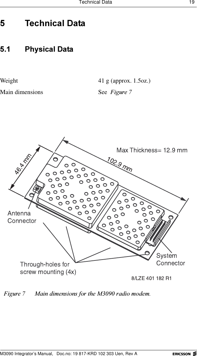
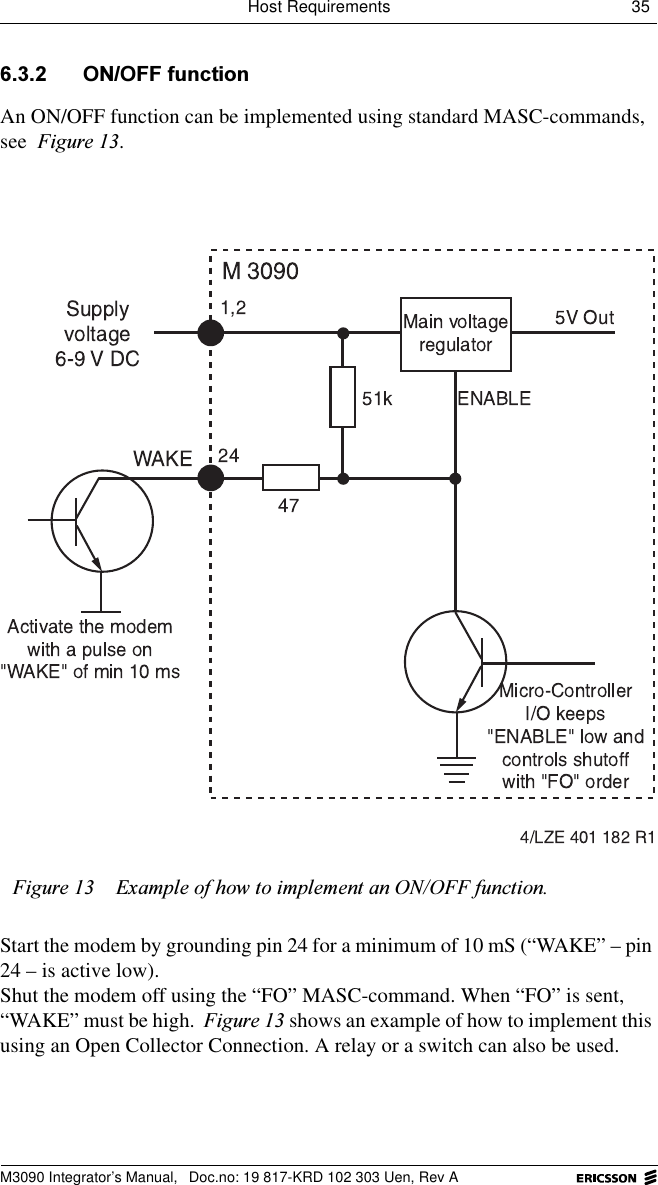
![14 M3090 Integrator’s ManualM3090 Integrator’s Manual, Doc.no: 19 817-KRD 102 303 Uen, Rev A$QWHQQD/HQJWKVThe following lengths are typical for half-wave and quarter-wave antennas in the frequency range that the M3090 radio modem uses. The lengths shown can vary somewhat, depending on the material that surrounds the core of the antenna. 6KRUWHQHG$QWHQQDVA shortened antenna is even shorter than a quarter-wave antenna. It can be designed to have characteristics that are nearly as good as those of a full-length antenna. $QWHQQD&RQFHSWVThe following sections present some fundamental concepts with regard to antennas. $QWHQQD*URXQG3ODQHAn antenna ground plane is an area under the antenna that is connected to ground and horizontal, flat and sufficiently wide. An antenna with a ground plane will function more efficiently.It is especially important that quarter-wave antennas have a ground plane. 3RODUL]DWLRQRadio waves radiate parallel to the antenna. The best reception is achieved when the receiving antenna is parallel to the transmitting antenna.The antennas of Mobitex radio base stations are vertical, which means that the radio waves are vertically polarized.Frequency range Half-wave antenna length Quarter-wave antenna length890 to 960 160 mm 80 mm](https://usermanual.wiki/Ericsson/M3090-MOBITEX.Users-Manual/User-Guide-68083-Page-18.png)