Extricom EXRP20E 802.11a/b/g Access Point User Manual Part 2 Revised
Extricom Ltd 802.11a/b/g Access Point Users Manual Part 2 Revised
Extricom >
Contents
- 1. Users Manual Part 1 Revised
- 2. Users Manual Part 2 Revised
Users Manual Part 2 Revised


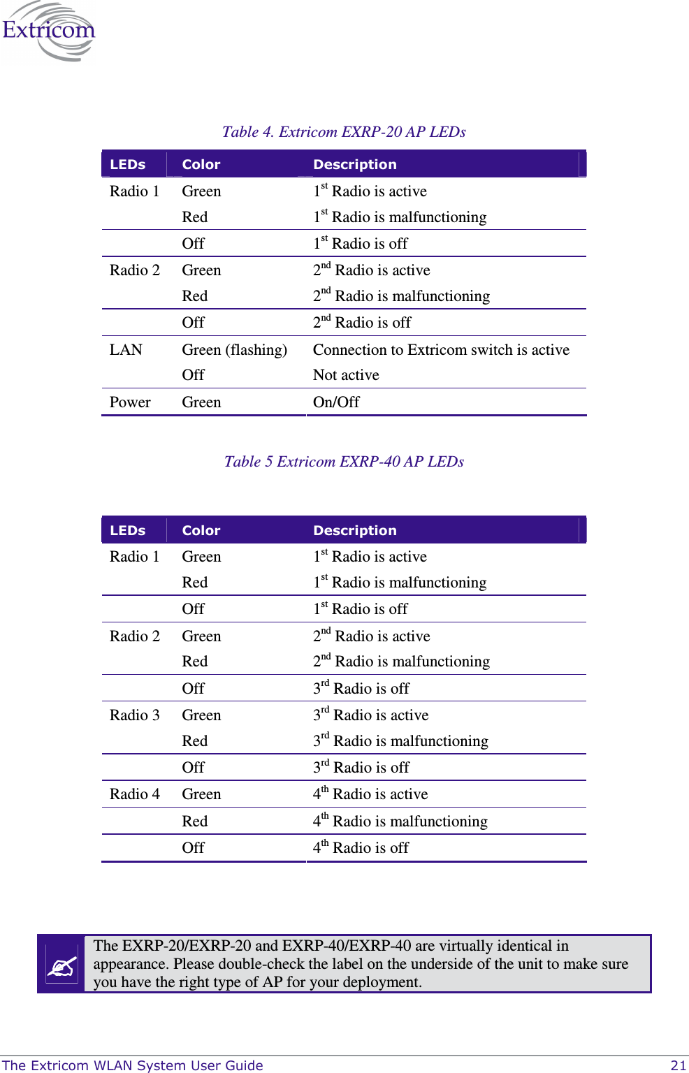
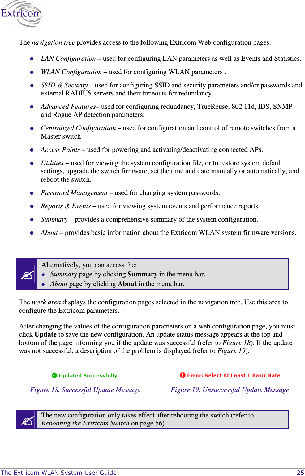
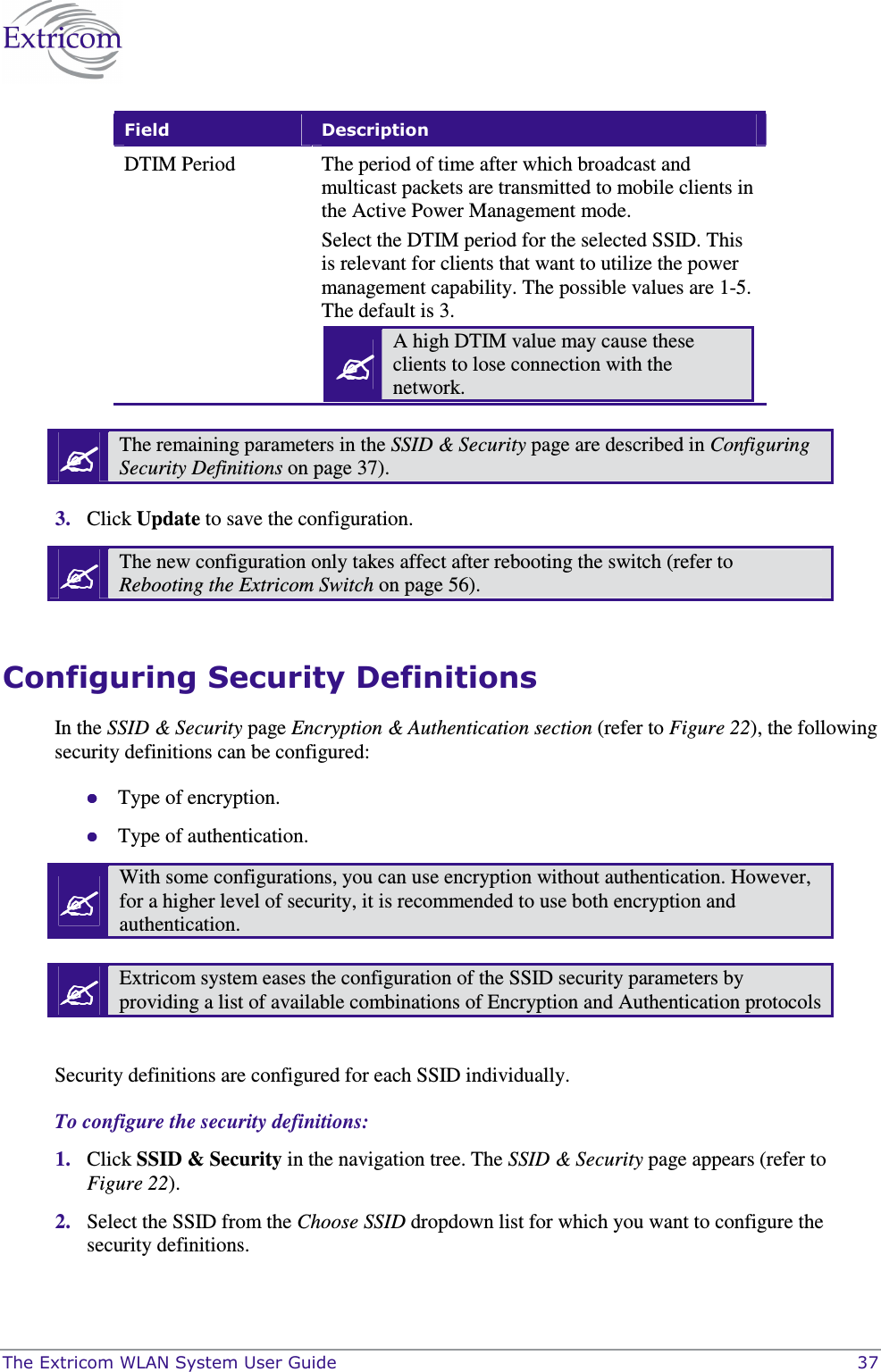
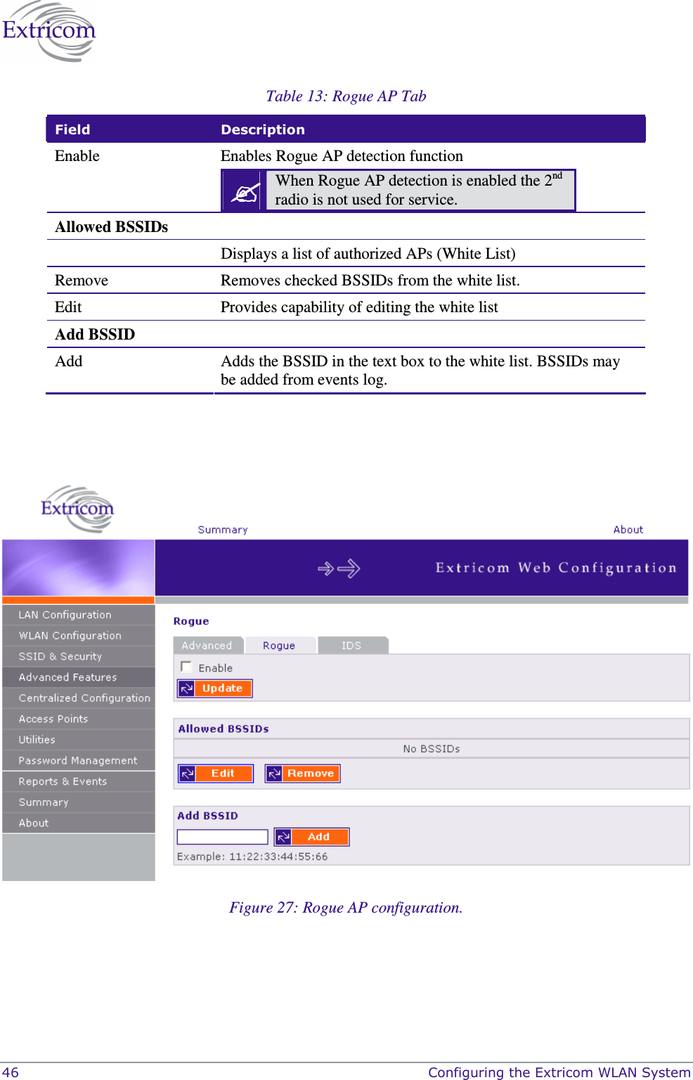
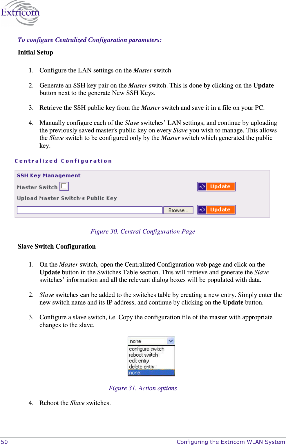
![The Extricom WLAN System User Guide 45 trap includes the AP’s BSSID, the switch port which detected the Rogue AP, the channel of the Rogue AP and the Rogue AP signal level (RSSI). 6. Rogue Removed <BSSID><Port><Radio><Channel><RSSI> - This trap is sent when a new Rogue AP is detected. The trap includes the AP’s BSSID, the switch port which detected the Rogue AP, the channel of the Rogue AP and the Rogue AP signal level (RSSI). 7. RADIUS Timeout <ESSID><# of timeouts> - This trap is sent when the RADIUS timeout had elapsed and includes the ESSID and the number of timeouts that occurred. 8. RADIUS Redundancy Selection Changed <ESSID><#of RADIUS>to<# of RADIUS> - This trap is sent when the RADIUS selection has been changed from one server to another, and includes the ESSID, the number of the previous server and the number of the new server. 9. No RADIUS <ESSID> - This trap is sent when the last RADIUS server failed and includes the ESSID. 10. Configured and connected APs of channel [<channel number>] - This trap provides a summary of all APs and their status. This trap is typically sent after an event of AP removal or connection from/to the switch. 11. AP <ap number in hex base> has been connected - This trap is typically sent after an event of connecting an AP to the switch. 12. AP <ap number in hex base> has been disconnected - This trap is typically sent after an event of disconnecting an AP from the switch. 13. Reference Host is up – This trap is sent when the Reference host is up and active. Sent by the Main switch. 14. Reference Host is down - This trap is sent when the Reference host is down. Sent by the Main Switch. 15. Standby Switch is up - This trap is sent when the Standby Switch is up & active. 16. Standby Switch is down - This trap is sent when the Standby Switch is down. 17. Inactive - Reference Host is down - This trap is sent when the Reference host is down, and hence the Main switch becomes inactive. 18. Inactive Standby Switch - Main Switch is up - This trap is sent when the Main Switch becomes active again and hence the Standby Switch becomes inactive (Switch over). 19. Main Switch is active again - This trap is sent when the Main Switch changes status from inactive to active and regains the Main switch status. 20. Failure detected in Main Switch - Switching Over. - This trap is sent when the Main Switch is about to go down and the Standby Switch is becoming Active. Rogue Tab A “Rogue” AP is an AP which is connected to an organization’s wired LAN without proper authorization. Such an AP represents a security hazard since the organization cannot control that AP’s over-the-air security measures. Rogue APs pose threats to the enterprise. These threats vary and may include any of the following: WEP key cracking. Password hijacking. IP and MAC spoofing. Channel jamming. To configure Rogue AP detection parameters refer to Table 13 and Figure 27](https://usermanual.wiki/Extricom/EXRP20E.Users-Manual-Part-2-Revised/User-Guide-977982-Page-31.png)