Fidelity Comtech FCI2400 Wireless LAN System with Amplifier User Manual Amp Users Manual pdf
Fidelity Comtech, Inc. Wireless LAN System with Amplifier Amp Users Manual pdf
UserManual.wiki
>
Fidelity Comtech
>
FCI2400 User Manual
Users Manual Revised
Navigation menu
Upload a User Manual
Namespaces
Wiki Guide
HTML
PDF
Info
Views
User Manual
Discussion / Help
Navigation

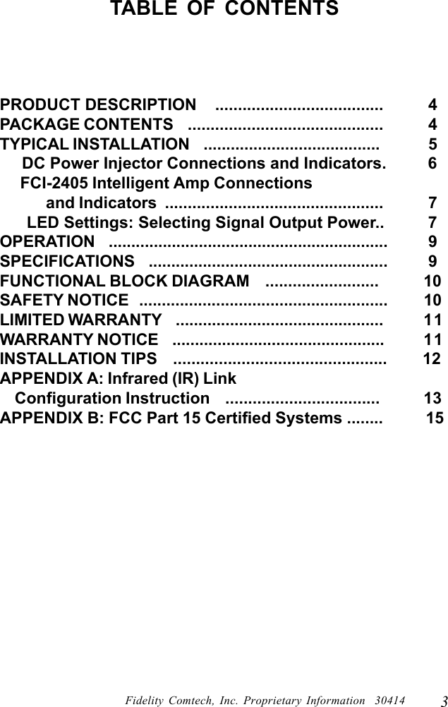
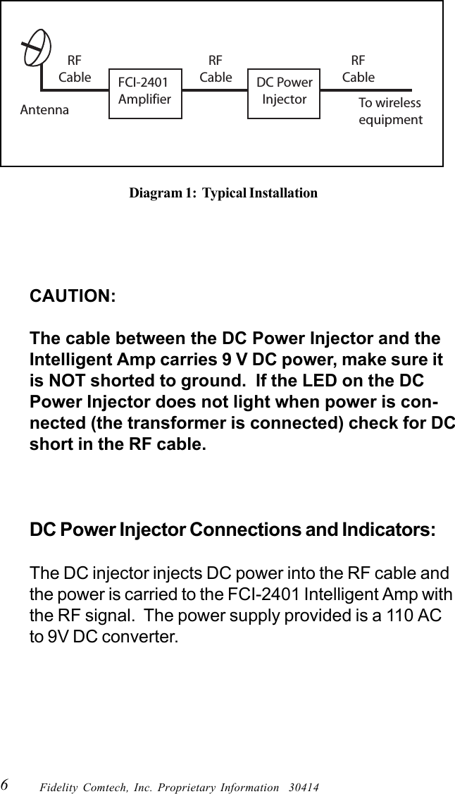
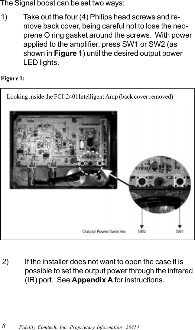
![7Fidelity Comtech, Inc. Proprietary Information 30414“RADIO” Connection:This “N” connector is connected to the wireless radioequipment via RF cable.“AMPLIFIER” Connection:This “N” connector is cabled to the FCI-2401 IntelligentAmp via the appropriate RF cable.FCI-2401 Intelligent Amp Connections andIndicators:“INPUT” Connection:This “N” connector is connected to the DC Power Injectorvia the transmission cable.“Antenna” Connection:This “N” Female connector connects to the antenna with anappropriate length of coax cable.LEDS: The LEDS indicate the current output powersettings.LED Settings: Selecting Signal Output Power[NOTE: Only Professional Installers are allowed to set or change the outputpower on the amplifier. Once these settings are established, the amplifierunit must be installed in a manor that the end user is prevented frommodifying the configuration].When power is applied one of the four (4) output powerindicator LEDs will light.To make changes to the power settings follow instructionsbelow:](https://usermanual.wiki/Fidelity-Comtech/FCI2400/User-Guide-321705-Page-8.png)