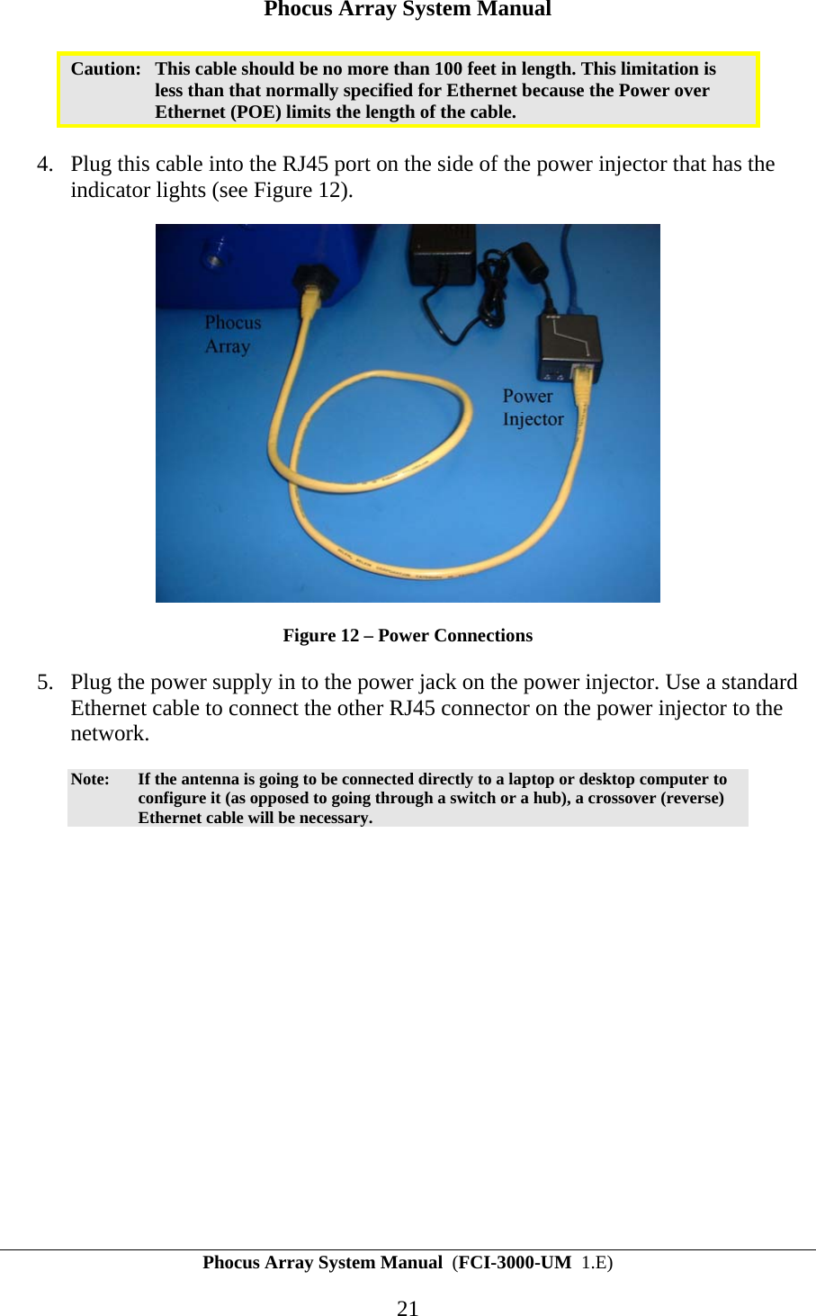
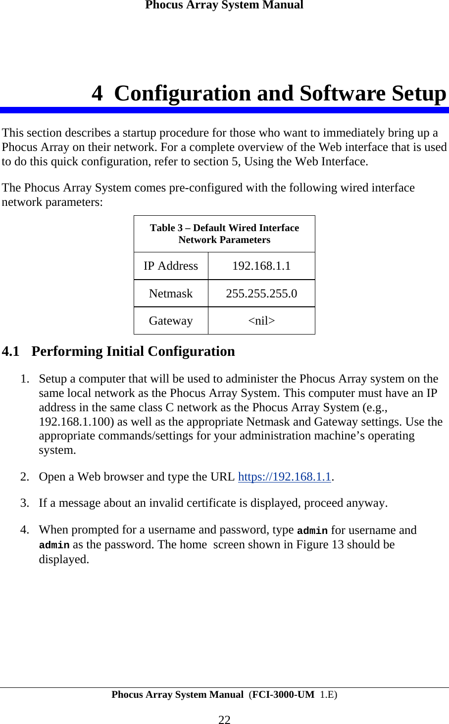
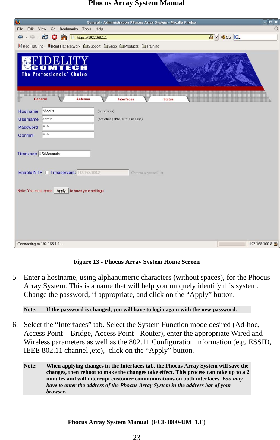
Fidelity Comtech FCI3000 Phased Array WLAN terminal User Manual Phocus 62006

Fidelity Comtech, Inc. Phased Array WLAN terminal Phocus 62006

User Manual

    Phocus Array™ System Manual  Part Number FCI-3000-UM   Document Version/Revision 1.E
Phocus Array System Manual  (FCI-3000-UM  1.E) 2 Information in this manual is subject to change without notice and does not represent a commitment on the part of Fidelity Comtech, Inc. Portions of the software described in this document are copyrighted by Fidelity Comtech, Inc and may not be copied or reproduced without written consent of Fidelity Comtech, Inc.  No part of this manual may be reproduced or transmitted in any form or by any means, electronic or mechanical, including photocopying and recording, for any purpose without the express written permission of Fidelity Comtech, Inc. © Copyright 2006 Fidelity Comtech, Inc. Fidelity Comtech, Inc 2400 Trade Centre Ave.  Longmont, Colorado, 80503, USA  General Information and Support: 303.678.8876 Fax 303.362.7545 Email: support@fidelity-comtech.com     This symbol indicates that this device provides a certain level of protection against electric shock.  This symbol indicates that the user must read and understand all instructions and warnings prior to use.  This symbol indicates that the associated jack is for a Universal Serial Bus connection. All rights reserved.  Reproduction, adaptation, or translation without prior written permission is prohibited, except as allowed under the copyright laws.   Phocus Array is a trademark of Fidelity Comtech, Inc. All other brand and product names mentioned in this document are trademarks and/or registered trademarks of their respective holders.
Phocus Array System Manual  (FCI-3000-UM  1.E) 3 TABLE OF CONTENTS 1 INTRODUCTION.............................................................................................................................. 6 1.1 ABOUT THIS MANUAL .................................................................................................................... 8 1.1.1 Documentation Conventions................................................................................................... 8 1.1.2 Device Description and Specifications................................................................................... 8 1.1.3 Warnings and Precautions...................................................................................................... 9 1.1.4 Maintaining Device Effectiveness........................................................................................... 9 1.1.5 Definitions............................................................................................................................... 9 2 PRINCIPLES OF BEAM STEERING .......................................................................................... 11 2.1 THEORY........................................................................................................................................ 11 2.2 THE PHOCUS ARRAY SYSTEM IMPLEMENTATION ......................................................................... 11 2.3 ADDITIONAL BEAM PATTERNS ..................................................................................................... 14 3 INSTALLATION AND HARDWARE SET UP ........................................................................... 16 3.1 INSTALLATION CONSIDERATIONS ................................................................................................. 18 3.1.1 Safety..................................................................................................................................... 18 3.1.2 How to Install your Phocus Array System Safely ................................................................. 18 3.1.3 Placement and Performance................................................................................................. 19 3.2 INSTALLATION PROCEDURE.......................................................................................................... 20 4 CONFIGURATION AND SOFTWARE SETUP ......................................................................... 22 4.1 PERFORMING INITIAL CONFIGURATION ........................................................................................ 22 5 USING THE WEB INTERFACE................................................................................................... 25 5.1 USING THE WEB INTERFACE......................................................................................................... 25 5.2  GENERAL TAB.............................................................................................................................. 25 5.3  ANTENNA TAB.............................................................................................................................. 26 5.3.1 Configure Antenna................................................................................................................ 26 5.3.2 Monitor Antenna................................................................................................................... 30 5.3.3 Manage Stations.................................................................................................................... 32 5.4  INTERFACES TAB ......................................................................................................................... 33 5.5  STATUS TAB ................................................................................................................................ 36 6 USING THE SSH INTERFACE..................................................................................................... 37 6.1 PRECAUTIONS WHEN WORKING UNDER THE HOOD ..................................................................... 37 6.2 USEFUL LINUX COMMANDS ......................................................................................................... 38 6.3 CHANGING THE ROOT PASSWORD ................................................................................................ 38
Phocus Array System Manual  (FCI-3000-UM  1.E) 4 6.4 KISMET......................................................................................................................................... 39 7 HARDWARE PLATFORM DETAILS ......................................................................................... 40 APPENDIX A - DETAILED DESCRIPTION OF THE PHOCUS ARRAY LINUX SOFTWARE................................................................................................................................................................... 43 A.1 DISTRIBUTION ANCESTRY................................................................................................................ 43 A.2 USER ACCOUNTS ............................................................................................................................. 43 A.3 FILE SYSTEM.................................................................................................................................... 43 A.4 BOOT PROCESSES............................................................................................................................. 43 A.5 PACKAGES ....................................................................................................................................... 45 APPENDIX B - DEFAULT PASSWORDS AND IP PARAMETERS .............................................. 47 APPENDIX C - CONTACT INFORMATION.................................................................................... 48 Table of Figures Figure 1 - Phocus Array Antenna System in a Wireless Access Point Application.....................................................................6 Figure 2 – Phocus Array System Block Diagram........................................................................................................................7 Figure 3 - Omni Antenna Pattern - State "0”.............................................................................................................................13 Figure 4 - Factory Default Antenna Patterns “State 12” and “State 15”....................................................................................14 Figure 5 - Sector Antenna Pattern..............................................................................................................................................15 Figure 6 - Two Lobe Pattern......................................................................................................................................................15 Figure 7 - Antenna in Outdoor Enclosure..................................................................................................................................16 Figure 8 – Power Cables, Software, and Accessories................................................................................................................17 Figure 9 - Right Angle Mounting Hardware..............................................................................................................................17 Figure 10 - Pole Mounting Hardware........................................................................................................................................17 Figure 11 - Bottom View showing Orientation Tab ..................................................................................................................20 Figure 12 – Power Connections.................................................................................................................................................21 Figure 13 - Phocus Array System Home Screen........................................................................................................................23 Figure 14 - Antenna Configure Page.........................................................................................................................................26 Figure 15 - Set Beamsteering Mode ..........................................................................................................................................28 Figure 16 - Upload New Patterns...............................................................................................................................................30 Figure 17 - Monitor Antenna.....................................................................................................................................................31 Figure 18 - Managing Associated Stations ................................................................................................................................33 Figure 19 - Interfaces Page - Upper Portion..............................................................................................................................34 Figure 20 - Interfaces Page - Lower Portion..............................................................................................................................35 Figure 21 - Status Page..............................................................................................................................................................36 Figure 22 – Internal System Block Diagram .............................................................................................................................41
Phocus Array System Manual  (FCI-3000-UM  1.E) 5  Table of Tables Table 1 – Device Description and Specifications........................................................................................................................8 Table 2 – Terms and Definitions .................................................................................................................................................9 Table 3 – Default Wired Interface Network Parameters............................................................................................................22 Table 4 – Default Wired Interface IP Address Parameters........................................................................................................47 Table 6 – Default Wireless Interface IP Address Parameters....................................................................................................47
Phocus Array System Manual Phocus Array System Manual  (FCI-3000-UM  1.E) 6 1 Introduction This is the installation and user manual for Fidelity Comtech’s Phocus Array system. The Phocus Array System is an IEEE 802.11b/g radio and phased array antenna system designed for outdoor use and housed in one package that can act as an access point or as a client station.    Figure 1 - Phocus Array Antenna System in a Wireless Access Point Application The unique feature of the Phocus Array System is that its antenna is electronically steerable. This means that by giving the Phocus Array System the appropriate software commands it can configure its antenna to an omni pattern, a 45-degree directional pattern in any direction, or many more complicated patterns.
Phocus Array System Manual Phocus Array System Manual  (FCI-3000-UM  1.E) 7  Figure 2 – Phocus Array System Block Diagram The Phocus Array System consists of the following components contained in a sealed outdoor enclosure: An embedded single board computer (SBC) running Linux-based software  An IEEE 802.11b/g based radio module wireless LAN card (WLAN) An 8:1 RF splitter Eight T/R (transmit/receive) modules that control the beam steering An array of eight antenna elements arranged in a circular pattern  Additionally, the system is shipped with an external power supply and Power Over Ethernet (POE) Injector that combines Ethernet signals and the correct power supply voltage to operate the unit. These two components should be mounted indoors separately from the outdoor mounted Phocus Array enclosure. There are several ways of managing the Phocus Array System. The primary one is the Web interface. This interface should be used to configure the Phocus Array System and for simple monitoring and maintenance. Additionally, there is a Secure Shell (SSH) interface to the SBC as well as several TCP/UDP ports designed for direct software access. The SSH interface requires considerable Linux expertise to use and must be used with caution to avoid rendering the system inoperable and possibly unrecoverable. The direct interfaces obviously require programming expertise. The remainder of this manual gives a basic overview of beam steering, walks you through the basic installation and configuration, explains the different interfaces and
Phocus Array System Manual Phocus Array System Manual  (FCI-3000-UM  1.E) 8 tools, and gives a much more detailed description of the internals of the Phocus Array System. The appendices contain the default passwords, details of the customized Linux distribution, and discussion of the direct software interfaces. 1.1 About this Manual The instructions in the following chapters assume the user is adequately familiar with the intended use and application of this device. Knowledge of the IEEE 802.11 wireless standard as well as concepts, protocols, and networking (e.g. TCP/IP and IEEE 802.3) are especially useful. 1.1.1 Documentation Conventions The following format conventions are used in this document to identify special information: Warning statements identify conditions or practices that could result in personal injury. Caution statements identify conditions or practices that could result in damage to equipment or loss of data. Notes: The displayed data in this document are for example purposes only.    The graphical illustrations in this document are for example purposes only and the hardware illustrated may differ from your hardware. 1.1.2 Device Description and Specifications Table 1 – Device Description and Specifications  Power Requirements:  Supplied external 120 VAC Power Supply, 24 VDC Output, 2.5 Amp Dimensions (w/o attachment hardware):  9.5” x 9.5” x 11” (24.1 cm x 24.1 cm x 28 cm) Weight (w/o attachment hardware):   10 lbs (4.5 kg) External Construction:  Outdoor mountable, sealed, high-impact, UV painted, ABS plastic radome over a powder-coated cast aluminum base. Base and radome are joined with a neoprene seal.  Operating Environment:  0°C to 60°C; 0 – 100% relative humidity. Not designed to be immersed in liquid. EMC Rating:  Designed to comply with FCC Part 15
Phocus Array System Manual Phocus Array System Manual  (FCI-3000-UM  1.E) 9 Table 1 – Device Description and Specifications  Wireless Protocols  IEEE 802.11 b/g 1.1.3 Warnings and Precautions Cautions: Always use the AC adapter that accompanied the system.  Using a different AC adapter can cause permanent damage to your system.   Always use outdoor-rated CAT5 or better Ethernet cable in order to comply with radiation and conducted emissions and immunity.   Do not attempt to immerse the device or accessories in water or cleaning fluid, as there are electronic components inside that will be permanently damaged. 1.1.4 Maintaining Device Effectiveness The recommended operating conditions for the device are 0° to 60°C, 0 to 100% humidity.  The recommended transport and storage conditions are -20°C to 50 °C; 0 to 95% non-condensing humidity; -1000 to 10,000 feet or 787.9-522.7 mm Hg.   Although the Phocus Array System is designed for outdoor use it should not be immersed in water or other fluids. The housing may be wiped clean with a soft cloth dampened with soapy water. 1.1.5 Definitions The following acronyms, abbreviations, and terms are used in this manual: Table 2 – Terms and Definitions Term Definition Azimuthally  Along the horizon. API  Application Programming Interface CF  Compact Flash. DHCP  Dynamic Host Configuration Protocol.  RFC 2131. DNS  Domain Name Server. ESSID  Extended Service Set IDentifier. IP  Internet Protocol. LED  Light Emitting Diode.
Phocus Array System Manual Phocus Array System Manual  (FCI-3000-UM  1.E) 10 Table 2 – Terms and Definitions Term Definition MAC  Media Access Control MADWiFi  Multiband Atheros Driver for WiFi WLAN  Wireless Local Area Network WEP  Wired Equivalent Privacy  POE  Power Over Ethernet RSSI  Receive Signal Strength Indication. SBC  Single Board Computer. SSH  Secure Shell State  An antenna configuration compromised of a set of weights, one for each T/R module, plus system-level drive and gain parameters that have been stored by the Phocus Array System and may be recalled. T/R module  Transmit/Receive module – a internal component of the Phocus Array System that is responsible for adjusting phase and magnitude of RF signals for one antenna element under the control of the SBC. TCP  Transmission Control Protocol.  RFC 793. UDP  User Datagram Protocol.  RFC 768. Weight  A particular set of the two parameters (magnitude and phase) that determine the basic behavior of a T/R module. WiFi  Wireless Fidelity.
Phocus Array System Manual Phocus Array System Manual  (FCI-3000-UM  1.E) 11 2 Principles of Beam Steering Before discussing the Phocus Array System, it is helpful to have a basic understanding of this feature that differentiates the Phocus Array System from other IEEE 802.11 radios. 2.1 Theory A phased array antenna is one that shapes its beam by applying the same signal to different antennas in an antenna system using different phases.  When the system combines two radio waves of the same frequency, the result depends on the phase difference. If the two radio waves are in phase (their positive peak occurs at the same time), the radio waves add. If they are 180 degrees out of phase (the positive peak of one occurs at the same time as the negative peak of the other), they reduce. In the latter case, if the two waves are the same amplitude, they will completely cancel each other out. If the phase difference is in between, the result will be in between. If there are more than two antenna elements, it is possible to create very complex beam patterns by choosing the amplitude and phase of the signal applied to each antenna element. The Phocus Array System uses an eight-antenna element uniform circular array.  This provides the ability to create a directional beam (about 45 degrees wide) in any direction azimuthally (i.e. along the horizon).   It also has the ability to form an omni-directional antenna, such that the signal can be transmitted in all directions simultaneously. It can also form much more complex beam patterns. Finally, the system can control a received signal in exactly the same way as it can a transmitted signal so that it can selectively receive from any direction, all directions at once, etc. 2.2 The Phocus Array System Implementation The Phocus Array System consists of a single radio (the IEEE 802.11b/g module) which handles both transmit and receive functions (refer to Figure 2). The antenna terminal of the radio connects to the common terminal of an eight-way splitter. Each of the other terminals of the splitter connects to a T/R module that connects to an antenna. The T/R module is a vector modulator and a bi-directional amplifier that is directed by the software. The software can specify precisely how much gain there will be in each direction, but also a precise phase delay. Each T/R module can be programmed with four parameters: the phase, the magnitude, the transmit drive, and the transmit gain. The Web interface enables you to specify the phase and the magnitude individually for each T/R module, but requires the same drive and gain for all the T/R modules. The phase and the magnitude are the primary adjustable parameters of the Phocus Array System. The phase sets the phase delay for the T/R
Phocus Array System Manual Phocus Array System Manual  (FCI-3000-UM  1.E) 12 module; allowable values are between 0 and 359 degrees of phase delay. The magnitude sets the amplification for the T/R module; allowable values are between 0 and 100 percent. The two additional parameters, the drive and the gain, are used in the exceptional case when you want the T/R module to behave differently when it is in receive mode than it does in transmit mode (normally it behaves identically in both modes).  Collectively a phase and magnitude set of these parameters for a T/R module is referred to as a weight. Setting the weights for all the T/R modules plus the overall drive and gain determines the beam pattern. The Phocus Array System is capable of storing the weights and the drive and gain; this stored configuration is referred to as a state. The Phocus Array System can store up to 169 states. Any state can be recalled to all the T/R modules with one command. Using these stored states, the Phocus Array System can dynamically change beam patterns much faster than it can if the SBC has to load the individual parameters for each T/R modules. States can be recalled using the “Antenna” Tab page of the Web interface (refer to section 5.3.1 Configure Antenna). The Phocus Array System can also compute certain beam patterns automatically. The “Antenna” page of the Web interface enables you to set a direction, and the Phocus Array System will compute the necessary beam pattern to create a unidirectional beam in the specified direction. The Phocus Array System can control its beam patterns using two basic modes: static and dynamic. In static mode, the beam pattern is configured and all radio operations are conducted using that pattern. The system remains fixed in the designated beam pattern until directed to change via the administration interface. In dynamic mode, the beam pattern can be different for each radio communication (packet) with each client. The dynamic mode obviously requires much closer cooperation between the radio and the antenna. Fidelity Comtech has pre-computed a number of beam patterns for the Phocus Array System. Seventeen of these patterns come pre-loaded into the Phocus Array System as States. You can load additional patterns. The following is brief description of some the factory default patterns: • Omni Pattern: Transmits/receives in a 360-degree circle. This pattern is pre-programmed as State 0 and is illustrated in Figure 3.  Note:  The pattern is illustrated by the blue line between the concentric green polar plot divisions. The antenna is implied at the center of the plot.
Phocus Array System Manual Phocus Array System Manual  (FCI-3000-UM  1.E) 13  Figure 3 - Omni Antenna Pattern - State "0” • Low Sidelobe Unidirectional Patterns (States 1-16): These patterns transmit/receive primarily in one direction. Each of the 16 states has a beam that is identical in shape (the half-power beamwidth for each is approximately 43 degrees), but each state is rotated 22.5 degrees more than the one before it. You can change the direction the beam is pointing by changing the active state (e.g.: from State 2 to State 5). The following example illustrates directional effect of changing the antenna from pre-programmed beam pattern State 12 (225 degrees), shown in red to State 15 (315 degrees) shown in blue.
Phocus Array System Manual Phocus Array System Manual  (FCI-3000-UM  1.E) 14  Figure 4 - Factory Default Antenna Patterns “State 12” and “State 15” 2.3 Additional Beam Patterns The factory default antenna patterns provide a balance between beam width, reach, and low sidelobe power, making them suitable for many applications.  Using the administration interface, you can steer the beam in a specific direction and the Phocus Array will synthesize a pattern dynamically. These generated patterns have different characteristics than the pre-computed “State” patterns. They are very efficient, have higher sidelobes, and offer the most precise control over the direction of the beam. This finer resolution (1 degree increments azimuthally) is not typically needed because the beam width is 43 degrees, but may be desirable in some applications. Finally, in addition to the factory default and the dynamically synthesized patterns described above, custom beam patterns can be designed and installed with different trade offs in mind. Two of the many possibly synthesizable patterns are illustrated in Figure 5 and Figure 6. Please contact Fidelity Comtech with your antenna pattern synthesis needs.
Phocus Array System Manual Phocus Array System Manual  (FCI-3000-UM  1.E) 15  Figure 5 - Sector Antenna Pattern   Figure 6 - Two Lobe Pattern
Phocus Array System Manual Phocus Array System Manual  (FCI-3000-UM  1.E) 16 3 Installation and Hardware Set Up Unpack the Phocus Array System from its shipping container. The system should consist of the following parts: Phase array antenna in outdoor enclosure (see Figure 7) Weatherproof Ethernet connector (see Figure 8) Power injector (see Figure 8) Power supply (see Figure 8) CDROM with Phocus Array System software (see Figure 8) Mounting bracket, either right angle (see Figure 9) or pole (see Figure 10) Four bolts to attach bracket to antenna (see Figure 9 or Figure 10  Figure 7 - Antenna in Outdoor Enclosure
Phocus Array System Manual Phocus Array System Manual  (FCI-3000-UM  1.E) 17  Figure 8 – Power Cables, Software, and Accessories  Figure 9 - Right Angle Mounting Hardware  Figure 10 - Pole Mounting Hardware
Phocus Array System Manual Phocus Array System Manual  (FCI-3000-UM  1.E) 18 3.1 Installation Considerations 3.1.1 Safety Warning:  Installation of this product near power lines is dangerous! For your safety, follow the installation directions. 3.1.2 How to Install your Phocus Array System Safely The following installation precautions and guidelines are extracted from the Recommendations of the U.S. Consumer Product Safety Commission on installing antennas.  These safety recommendations apply to all antennas. Each year, hundreds of people are killed, mutilated, or receive severe and permanent injuries when attempting to install an antenna. In many of these cases, the victim was aware of the danger of electrocution, but did not take adequate steps to avoid the hazard. For your safety, and to help you achieve a good installation, please read and follow the safety precautions below. They may save your life! That this is not complete list of instructions, precautions, and installation guidelines necessary to safely and effectively install the antenna. You should consult a professional, as well as observe local and national code requirements. 1. If you are installing an antenna for the first time, please, for your own safety as well as others, seek professional assistance. The professional can explain which mounting method to use for the size and type of antenna you are about to install. 2. Select your installation site with safety, as well as performance, in mind. REMEMBER: ELECTRIC POWER LINES AND PHONE LINES LOOK ALIKE. FOR YOUR SAFETY, ASSUME THAT ANY OVERHEAD LINES CAN KILL YOU. 3. Call your electric power company. Tell them your plans and ask them to come take a look at your proposed installation. This is a small inconvenience, considering YOUR LIFE IS AT STAKE. 4. Plan your installation procedure carefully and completely before you begin. Successful raising of a mast or tower is largely a matter of coordination. Each person should be assigned a specific task, and should know what to do and when to do it. One person should be designated as the leader/coordinator of the operation to call out instructions and watch for signs of trouble. 5. When installing your antenna, REMEMBER: DO NOT USE A METAL LADDER. DO NOT WORK ON A WET OR WINDY DAY. DO DRESS PROPERLY: shoes with rubber soles and heels, rubber gloves, long sleeved shirt or jacket.
Phocus Array System Manual Phocus Array System Manual  (FCI-3000-UM  1.E) 19 6. If the assembly starts to drop, get away from it and let it fall. Remember, an antenna, mast, cable, and metal guy wires are all excellent conductors of electrical current. Even the slightest touch of any of these parts to a power line completes an electrical path through the antenna and the installer – THAT’S YOU! 7. If ANY PART of the antenna system should come in contact with a power line, DON’T TOUCH IT OR TRY TO REMOVE IT YOURSELF. CALL YOUR LOCAL POWER COMPANY. They will remove it safely. If an accident should occur with the power lines, call for qualified emergency help IMMEDIATELY. 3.1.3 Placement and Performance Placement of the Phocus Array System can affect performance. Keep in mind that the number, thickness, and location of walls, buildings, trees, or other objects that wireless signals pass through or reflect off, may limit the range. Typical ranges vary depending on terrain, proximity to objects, types of materials and background RF noise. The key to maximizing range is to follow these basic guidelines. 1. Clear line-of-sight between the Phocus Array System and your network devices gives the best performance. 2. Keep the number of walls and ceilings between the Phocus Array System and other network devices to a minimum - each wall or ceiling can reduce your range from 3-90 feet (1-30 meters.) Position your devices so that the number of walls, trees, etc. is minimized. 3. Be aware of the direct line between network devices. A wall that is 1.5 feet thick (.5 meters), at a 45-degree angle appears to be just over 2 feet (.6 meters) thick. At a 2-degree angle it looks over 42 feet (14 meters) thick! Position devices so that the signal will travel straight through a wall or ceiling (instead of at an angle) for better reception. 4. Building materials can impede the wireless signal - a solid metal door or aluminum studs may have a negative effect on range. Try to position wireless devices and computers with wireless adapters so that the signal passes through drywall or open doorways and not other materials. 5. Keep your product away (at least 3-6 feet (1-2 meters)) from electrical devices or appliances that generate extreme RF noise.
Phocus Array System Manual Phocus Array System Manual  (FCI-3000-UM  1.E) 20 3.2 Installation Procedure 1. Attach the antenna to the bracket using the supplied bolts and fasten the bracket securely in its final location. There is an orientation tab on the bottom of the Phocus Array system housing that marks the 0 degree direction (see Figure 11). Notes:  Washers are not supplied with these bolts because threads in the base of the Phocus Array housing are self-locking.    The pole bracket requires a 1-inch pipe with an NPT thread.    If the Phocus Array System is to be used with the pole bracket, be aware that the pipe threads in the bracket are tapered and the bracket should be attached to the Phocus Array housing with the thicker center pad away from the housing.  Figure 11 - Bottom View showing Orientation Tab 2. Attach the supplied Ethernet connector to the end of a CAT5 (or better) cable.  If this is a temporary connection just to configure the antenna, an ordinary RJ45 connector will work. If the connection is permanent, use the supplied connector to ensure a weatherproof connection.  Caution:  Be sure to use outdoor rated CAT5 cable unless the antenna is to be installed in a sheltered location (cable will not be exposed to moisture or direct sunlight).  3. Put a standard RJ45 connector on the other end of the CAT5 cable.
Phocus Array System Manual Phocus Array System Manual  (FCI-3000-UM  1.E) 21 Caution:  This cable should be no more than 100 feet in length. This limitation is less than that normally specified for Ethernet because the Power over Ethernet (POE) limits the length of the cable.  4. Plug this cable into the RJ45 port on the side of the power injector that has the indicator lights (see Figure 12).   Figure 12 – Power Connections 5. Plug the power supply in to the power jack on the power injector. Use a standard Ethernet cable to connect the other RJ45 connector on the power injector to the network.  Note:  If the antenna is going to be connected directly to a laptop or desktop computer to configure it (as opposed to going through a switch or a hub), a crossover (reverse) Ethernet cable will be necessary.
Phocus Array System Manual Phocus Array System Manual  (FCI-3000-UM  1.E) 22 4 Configuration and Software Setup This section describes a startup procedure for those who want to immediately bring up a Phocus Array on their network. For a complete overview of the Web interface that is used to do this quick configuration, refer to section 5, Using the Web Interface. The Phocus Array System comes pre-configured with the following wired interface network parameters: Table 3 – Default Wired Interface Network Parameters IP Address  192.168.1.1 Netmask 255.255.255.0 Gateway <nil> 4.1 Performing Initial Configuration 1. Setup a computer that will be used to administer the Phocus Array system on the same local network as the Phocus Array System. This computer must have an IP address in the same class C network as the Phocus Array System (e.g., 192.168.1.100) as well as the appropriate Netmask and Gateway settings. Use the appropriate commands/settings for your administration machine’s operating system.  2. Open a Web browser and type the URL https://192.168.1.1.  3. If a message about an invalid certificate is displayed, proceed anyway.  4. When prompted for a username and password, type admin for username and admin as the password. The home  screen shown in Figure 13 should be displayed.
Phocus Array System Manual Phocus Array System Manual  (FCI-3000-UM  1.E) 23  Figure 13 - Phocus Array System Home Screen 5. Enter a hostname, using alphanumeric characters (without spaces), for the Phocus Array System. This is a name that will help you uniquely identify this system. Change the password, if appropriate, and click on the “Apply” button.  Note:  If the password is changed, you will have to login again with the new password. 6. Select the “Interfaces” tab. Select the System Function mode desired (Ad-hoc, Access Point – Bridge, Access Point - Router), enter the appropriate Wired and Wireless parameters as well as the 802.11 Configuration information (e.g. ESSID, IEEE 802.11 channel ,etc),  click on the “Apply” button.  Note:  When applying changes in the Interfaces tab, the Phocus Array System will save the changes, then reboot to make the changes take effect. This process can take up to a 2 minutes and will interrupt customer communications on both interfaces. You may have to enter the address of the Phocus Array System in the address bar of your browser.
Phocus Array System Manual Phocus Array System Manual  (FCI-3000-UM  1.E) 24 Note:  When these changes are applied to the wired network, the IP Address of the Phocus Array System will change, requiring reconfiguration of your administration computer or network to continue communicating with the Phocus Array System. Once the above steps have been completed, a wireless client should be able to find and associate the Phocus Array System in AP Mode.
Phocus Array System Manual Phocus Array System Manual  (FCI-3000-UM  1.E) 25 5 Using the Web Interface This section discusses the Web interface for the Phocus Array System. For a quick start guide to simply getting a Phocus Array System up and running on a network, refer to section 4, Configuration and Software Setup. Most common tasks can be performed using the Web interface for the Phocus Array System, making it the preferred method to access the System. Common tasks include: Installation and setup of the wireless and network parameters. Monitoring client associations. 5.1 Using the Web Interface To access the Web interface, perform steps 1–4 in section 4.1 (page 22). There are four different categories of settings, each accessible from a tab at the top of the page:  General Antenna Interface Status  These categories are discussed in the following subsections. 5.2 General Tab The general setup tab enables you to set general parameters that apply to Phocus Array system. These are: the hostname, username and password for the Web interface (these are different than the name and password for Linux root access if you log directly into the Linux system via a secure shell), and NTP services and time zone control. To change any of these parameters, enter the new parameter into the field on the Web page and click on “Apply.” Note, if you fail to click on the “Apply” button, the changes will be lost (this is true for any page in the Web interface). The Timezone parameter for the United States are: US/Alaska, US/Aleutian, US/Arizona, US/Central, US/East-Indiana, US/Eastern, US/Hawaii, US/Indiana-Starke, US/Michigan, US/Mountain, US/Pacific, and US/Samoa.
Phocus Array System Manual Phocus Array System Manual  (FCI-3000-UM  1.E) 26 5.3  Antenna Tab The Antenna page has three buttons allowing user control of three antenna related functions: • Configure – to download and review new patterns, set the antenna mode • Monitor – to monitor client associations and their direction • Manage Stations – to managing naming of associated client stations 5.3.1 Configure Antenna The Configure Antenna page, shown in  Figure 14, contains three separate but related functions allowing the user to configure and review the antenna system behaviors. Using the controls on this page a user can  • Review graphic visualizations of loaded antenna patterns using the pane on the right side titled “Review Loaded Patterns”,   • Set Beamsteering Mode, enabling either a “Static” antenna pattern (e.g. Omni, State 1 – North, etc.) or a “Dynamic” mode. • Upload new antenna patterns, replacing the factory default patterns.    Figure 14 - Antenna Configure Page
Phocus Array System Manual Phocus Array System Manual  (FCI-3000-UM  1.E) 27 Caution:  Using the Configure Antenna feature can be harmful to your system. Changing the States can lead to erratic behavior. Make sure you understand what you’re doing. Consult with Fidelity Comtech if you need assistance and required patterns beyond the factory installed states.   5.3.1.1 Review Loaded Antenna Patterns You can review a graphic of each of the currently loaded patterns in the Phocus Array System by clicking on the “Next” or “Previous” buttons. Clicking on these buttons does not change the state or operation of the system. Keep in mind the orientation mark illustrated in these graphics and their relationship to the actual orientation of the mark on the Phocus Array System case.  Dynamic mode is not illustrated in this pane. 5.3.1.2 Set Beamsteering Mode Utilizing the Set Beamsteering Mode control the user can select the antenna system configuration. • A static state selection such as State 1 - North configures the antenna to a particular pattern and leaves it that way until administered differently. Both transmitted and received radio communications use the designated pattern. • Dynamic mode allows the Phocus Array System to determine approximately where the client radios are located and sends any transmissions to a client radio using one of the system patterns for that client (receives are done with an omni-directional pattern). Defining custom patterns may improve your performance depending on your application. See Section 2.3 for more on custom patterns.   5.3.1.2.1 Static States Selections A user can select a static state, as shown in Figure 15, and thereby disable scanning of client radios and fix the antenna in a predetermined pattern or azimuth.  • Omni is State 0 which is preset to the omni-directional pattern for the factory configured patterns. All communications (transmit and receive) are performed with this omni-directional pattern   •  State 1 to State 16 creates an antenna pattern that optimizes transmissions and receives in one direction. You can choose 0 to 359 degrees in 1-degree increments. “0” degrees is indicated on the Phocus Array System by the orientation tab that is stamped on the bottom of the housing (see Figure 11). If you look down on the antenna from above as if it were a clock face, 90 degrees is at 9 o’clock, 180 degrees is at 6 o’clock and 270 degrees is at 3 o’clock.
Phocus Array System Manual Phocus Array System Manual  (FCI-3000-UM  1.E) 28 The “Apply” button must be clicked for the new antenna pattern to take effect. This setting will take effect immediately and remain effective even through system power cycles.   Figure 15 - Set Beamsteering Mode  Generally you’ll get the best reception using the Phocus Array System in the following modes (best first) and adhering to the installations recommendations in Section 3.1.3. 1) Custom Pattern (designed for your application). 2) State 1 to State 16  Patterns – The factory pre-defined patterns using States have the following trade offs – good efficiency, slightly shorter reach with much smaller sidelobes. They also generate less interference, provide better spectral reuse, and afford more privacy. 3) Default Pattern (Omni mode).
Phocus Array System Manual Phocus Array System Manual  (FCI-3000-UM  1.E) 29 5.3.1.2.2 Dynamic Mode In Dynamic Mode, the Phocus Array System periodically “scans” (every Scan Interval) using all stored directional beam patterns (States) to determine which pattern results in the best signal from the particular client’s radio. All signal values are stored, and the best signal value determines the beam pattern that will be used for transmitting data to that specific station. If Dynamic Mode is selected, you should select the scan interval. Essentially, the scan interval tells the Phocus Array System how often to stop and recompute the directional optimization for each associated wireless client.  The Scan Interval can be set to 1-300 seconds.  Under normal circumstances Fidelity Comtech recommends that the scan time be set at 5 seconds.  Consult with Fidelity Comtech if you have special requirements for scanning. 5.3.1.3 Upload New Patterns By utilizing the “Upload New Pattern” control, a user can upload a new set of patterns and replace the factory default patterns. Uploading a new set of patterns permanently overwrites the factory default patterns. Contact Fidelity Comtech for custom patterns such as those described in Section 2.3. To upload a new patterns file, as illustrated in Figure 16, first select the “Browse” button to navigate to the location of the file, select an appropriate file, and then press “Upload”.  The upload and programming of new patterns into the system takes about 1 minute, after which the antenna system will be in the static “Default” state.   Review the newly download patterns using the Review Antenna Patterns control. Proceed to the Set Beamsteering Mode pane to activate a different static pattern or Dynamic mode.
Phocus Array System Manual Phocus Array System Manual  (FCI-3000-UM  1.E) 30  Figure 16 - Upload New Patterns  5.3.2 Monitor Antenna  When in Dynamic Mode the Phocus Array System periodically scans through all static states (except the Default state) searching for the strongest RSSI value of associated client stations and determines their approximate direction (or more precisely the Angle of Arrival of its packets). Utilizing the Antenna Tab, Monitor button you can view the results of the most recent antenna system scan in Dynamic mode.  After pressing the “Monitor” button in your browser, you may be asked to accept and download a Java component from the Phocus Array System. This Fidelity Comtech authored component is a graphic allows you to “see” a radar-like display of the direction of 802.11-associated clients. Press “Yes” to accept the download of the component. See Figure 17 for an example of the page, in this case, illustrating a single client station (MAC 00:06:25:ac:df:ee) associated with the system. By clicking the “Plot” checkbox in the first column, the radar display will draw a line illustrating the “angle of arrival” (i.e. the approximate direction) of the station with relationship to the Phocus Array System.
Phocus Array System Manual Phocus Array System Manual  (FCI-3000-UM  1.E) 31 Note the green orientation mark at 0 degrees at the top of the radar display – it represents the orientation mark on the Phocus Array System base, as if you are looking down on the top system.  The “Refresh Screen” control at the top of this screen sets the rate at which the browser asks the Phocus Array System for data to display, and thus updates the radar display. (This is different than the Scan Interval described on the Antenna Configuration page, which is how often the antenna system scans the for station position.) Ideally the Refresh Screen setting should be the same or larger than the Scan Interval. If a station is moving (e.g. a laptop PC or handheld pocket computer) the radar display will up automatically update changes in apparent direction of the client. Note, even if a client station is stationary, the display may occasionally show different directions for the client. This is normal and reflects the changing conditions of the RF environment, including reflections, obstructions, and possibly movement of other objects in the environment or the fact that a client may be aligned between 2 antenna states.   Figure 17 - Monitor Antenna
Phocus Array System Manual Phocus Array System Manual  (FCI-3000-UM  1.E) 32 Note:  Display of direction and RSSI values only is relevant to Dynamic mode. Even though Station MAC addresses are listed in the Associated Stations Monitor table when Static mode is selected; the radar plot produced is only relevant to the Dynamic mode scans.  Note:  If a new station associates, its MAC will automatically appear in the Associated Stations Monitor table.   If you download new antenna patterns with a greater or less number of states, the display will adapt to however many states are loaded in the Phocus Array System.  If a new client station associates with the Phocus Array System, it’s MAC will automatically appear in the Associated Stations Monitor Table with a name of “unnamed”. The Phocus Array System then attempts to scan the new client station and if successful, a direction will be established it. To display the direction, click the Plot checkbox adjacent to the MAC. If the client station can’t be successfully scanned, it’s MAC address still appears in the Associated Stations Monitor table, but with a 0 RSSI value.  Note:  With the antenna in DYNAMIC mode an associated client station with an incomplete/indeterminate scan will appear as a MAC address or name in the center of the radar display.   Note:  With the antenna in STATIC mode an associated client station MAC/name will appear in the center of the radar display.   An incomplete dynamic mode scan can be the result of a client station being turned off or moving out of range.  5.3.3 Manage Stations By utilizing the Manage Stations button on the Antenna Tab, as shown in Figure 18, you can give a Nickname (name) to a client station. This name is local to the Phocus Array System and is not related to 802.11 broadcast nickname.  Until a client station is given a name using this page, the Monitor described in Section 5.3.2  page only displays MAC addresses in the radar plot. Naming stations allows you to assign meaningful names to clients in your network. It also makes it easy to see when a new (perhaps unwelcome) station arrives in the network.  To assign a name, type a character string into the text box to the right of MAC address. It can be anything you feel descriptive of the client such as “Ricks Laptop” or “Node in Room 6”. After entering the desired names, press “Apply” to have the Phocus Array System memorize the MAC/Name pair. This name will remain in the system associated with the MAC through power cycles, and even if the client station becomes disassociated. The next time station associates the system will automatically display the name on this page as well as the Antenna Tab – Monitor page.
Phocus Array System Manual Phocus Array System Manual  (FCI-3000-UM  1.E) 33   Figure 18 - Managing Associated Stations Note:  After clicking “Apply” the names will be stored, but the screen may not refresh correctly on this page. Press your browsers “Refresh” button to see the newly assigned names.  5.4 Interfaces Tab The Interfaces page, shown in Figure 19, administers the overall function of the Phocus Array System as an Access Point – Bridge, Access Point – Router, or Ad-hoc (Mesh) Network. Once a system function is selected, the appropriate fields in the lower parts of the page can be completed with information for your application.
Phocus Array System Manual Phocus Array System Manual  (FCI-3000-UM  1.E) 34  Figure 19 - Interfaces Page - Upper Portion The Wired and Wireless interfaces can be configured with static IP addresses or utilizing DHCP services. Additionally Wireless interface parameters are available configure the radio mode, channel, ESSID and WEP security.  An Access Control List (ACL) field allows user entry of a list of MAC addresses for stations that are permitted to communicate over the wireless interface.  Entries should be comma-separated. An empty list allows all stations with the appropriate configuration ( b/g/auto radio-mode, channel, WEP key, ESSID) to associate and communicate.  Note:   In Release 0.3.1 the RTS Threshold administration is not functional and will not activate RTS/CTS protection of transmissions.
Phocus Array System Manual Phocus Array System Manual  (FCI-3000-UM  1.E) 35 In the lower portion of the page as shown in Figure 20  includes a DNS (Domain Name Server) entry-field. Entries should be comma separated.  Figure 20 - Interfaces Page - Lower Portion The “Submit” button must be pressed to save the modifications and make them take effect. As a normal part of processing the settings the system will reboot after “Submit” is pressed. After approximately 2 minutes the system will be in service again. Warning: Pressing “Submit” on the Interfaces page will cause new setting to take effect and take the system out of service for approximately 2 minutes. Subsequently you may have to direct your browser back to the Phocus Array System home page.
Phocus Array System Manual Phocus Array System Manual  (FCI-3000-UM  1.E) 36  5.5 Status Tab The Status page, shown in Figure 21, provides hardware and software information about the system as well as the system up time. Most fields are determined at boot time, except Date/Time and Up Time which are updated each time the page is accessed or refreshed. The Wireless MAC address field is useful when administering the ACL list on other meshing nodes.  Figure 21 - Status Page
Phocus Array System Manual Phocus Array System Manual  (FCI-3000-UM  1.E) 37 6 Using the SSH Interface This section discusses the details of using the SSH (Secure Shell) interface.  The Phocus Array System runs a SSH server so that you can set up a Secure Shell connection to directly log-in to the control computer. To do this there has to be an SSH client that will run on the management machine. If your PC is running Windows, PuTTY is a free SSH client. PuTTY can be found on the Web at http://www.chiark.greenend.org.uk/~sgtatham/putty/. There are also other shareware and commercial SSH clients available. To log in, on your administration computer start the SSH client and enter the IP Address of the Phocus Array System. Log-in with the name and password of any user on the Linux on-board computer. The default password for “root” user is “fci3000”. Note:  If you are going to use this interface, it is important that you have a good understanding of Linux and the particular variant that runs on the Phocus Array System (the Pebble distribution of Debian Linux).  See http://www.debian.org for some information on Debian Linux and http://nycwireless.net/tiki-index.php?page=PebbleLinux for information on the Pebble distribution. Fidelity Comtech has made substantial modifications to this distribution. The most important of these are discussed in Appendix A - Detailed Description of the Phocus Array Linux . 6.1 Precautions When Working Under the Hood At its core, the Phocus Array System is an embedded Debian Linux system. It boots as any normal system using the configuration scripts found in /etc/rc3.d (/etc/init.d) and various system configuration files (e.g. /etc/network/interfaces).  Utilizing the Web interface, users modify the underlying system configuration files when they the press “Submit” or “Apply.”  This is important to note if you use the SSH interface and choose to hand modify the configuration files.  Caution:  Users working via the SSH command line interface and modifying Linux system configuration files should be aware the subsequent use of the Web interface may overwrite their changes, rendering the system unusable or inoperable.
Phocus Array System Manual Phocus Array System Manual  (FCI-3000-UM  1.E) 38 6.2 Useful Linux Commands Linux commands that may be of particular interest in managing the Phocus Array System include: ifconfig  Command to view or configure interfaces. Type “ifconfig” to display the current configuration for active interfaces. Type “ifconfig --help” for a list of options. netstat  Command to view interface statistics or routing tables. Type “netstat -i” for statistics on interfaces. Type “netstat –r” for a routing table. Type “netstat --help” for a list of options. iwconfig  Command to view or configure wireless interfaces. Type “iwconfig” to display the current configuration for wireless interfaces. Type “iwconfig -–help” for a list of options. iwlist  Command to retrieve wireless statistics from an interface. Type “iwlist ath0 <parameter>” for information about a parameter. Type “iwlist -–help” for a list of parameters. iwpriv  Command to set and retrieve private (as opposed to generic) parameters for a wireless interface. Type “iwpriv ath0” for a list of parameters. Type “iwpriv -—help” for the command line format. remountrw  Command script from Fidelity Comtech to mount the flash-based file system as read/write. remountro Command script from Fidelity Comtech to mount the flash-based file system as read only. 6.3 Changing the Root Password When you first use the system, you should change the root password from the default of “fci3000” to something only you know. To do this, perform the following steps: 1. Log in as root.  2. Mount the basic file system as read/write (normally the Phocus Array System runs with its file system as read-only) by running the script “remountrw”.  3. Run the “passwd” command and provide the requested information.  4. Run the script “remountro” to return the file system to read-only state.
Phocus Array System Manual Phocus Array System Manual  (FCI-3000-UM  1.E) 39 6.4 Kismet Kismet is a publicly available wireless sniffer that comes already loaded on the Phocus Array System. The home page for Kismet is http://www.kismetwireless.net. To run Kismet, perform the following steps: 1. Connect using SSH into the Phocus Array System as root and type /etc/init.d/kismet start. This will start the Kismet server. This window must be left open (unless the server is put into the background).  Note:  When the server starts, the Phocus Array System will be put into monitor mode; and when it quits, the Phocus Array System will stay in that mode. You must either reboot the Phocus Array System or change the mode directly with the iwconfig command before it will perform as an access point again.  2. Open a second SSH window into the Phocus Array System and type kismet_client. This will start the client.  3. Type h to display the available commands. Be sure to scroll down to the bottom of the page to see all the commands.  4. You can run a Kismet client on a separate system from the Phocus Array System – this will allow you to capture or log all the packets (the Phocus Array System does not have the memory necessary to do this). Once you have captured packets you can play the packets back with a tool like Ethereal (http://www.ethereal.com). To do this, you will have to find the client or build it from the source on your client system.
Phocus Array System Manual Phocus Array System Manual  (FCI-3000-UM  1.E) 40 7 Hardware Platform Details A block diagram of the Phocus system is shown in Figure 22.  The system is comprised of a single board PC with a flash file system and a wireless LAN card.  The Phased array subassembly connects to the antenna port of the wireless LAN card and uses the serial port to send and receive commands. A splitter, located between the WLAN card and the T/R modules, splits the signal from the WLAN card into eight equal signals that are in phase.  The splitter is a passive device that splits the signals evenly apart when transmitting and combines them together when receiving.  Each of the eight outputs of the splitter is fed to the input of a T/R module. The T/R module is responsible for applying the correct amplitude and phase to the signals so that the desired beam is formed. Each of the eight antenna elements in the Phased Array subassembly has a T/R module associated with it.  Besides phase shifting, the T/R module provides amplification during both transmission (high power amplification) and reception (low noise amplification).
Phocus Array System Manual Phocus Array System Manual  (FCI-3000-UM  1.E) 41  Figure 22 – Internal System Block Diagram  The T/R modules are installed on a backplane that provides power and an RS-485 multi-drop communications interface. The single board computer (SBC) is a Soekris Net4511.  This is a 100 MHz x86 class processor based on the SC520 from AMD.  It has 64MB of RAM.  The Phocus software executable normally ships on a 256MB Compact Flash card. Each T/R Module includes a microcontroller that processes the commands from the central CPU, applies a factory calibration factors, and converts them to analog readings that set the phase and magnitude of the signal.
Phocus Array System Manual Phocus Array System Manual  (FCI-3000-UM  1.E) 42 There are two LEDs located on the T/R module.  The bottom LED acts as a power indicator.  Once the T/R module microcontroller is powered up, the power LED is on.  The other LED acts as a synchronization indicator indicating communication between the SBC and T/R modules.   The backplane provides the RS-232 to RS-485 conversion for the SBC to T/R modules communication.  The backplane also provides the location information for the T/R modules.  The T/R modules are numbered 0 through 7, which is based on the backplane connection to the T/R module.  This is necessary because each T/R module controls an antenna element.  The T/R module reads its number (0-7) based on its backplane connection and then performs antenna element control based on this information.  The backplane provides power regulation for all T/R modules.   The wireless LAN card is an Atheros chipset based card in a mini-PCI format with the driver based on the MADWiFi driver software.
Phocus Array System Manual Phocus Array System Manual  (FCI-3000-UM  1.E) 43 Appendix A -  Detailed Description of the Phocus Array Linux Software Many aspects of the Phocus Array System Linux software will be familiar to anyone who has experience with Linux systems.  The Phocus system is simpler than many other distributions in the sense that it has fewer daemons running than a typical graphics workstation or server. This section describes the details of the configuration, user accounts, and customizations delivered in this Linux-based system.  A.1 Distribution Ancestry The Phocus Array System processor is running Linux, based on the Pebble Linux distribution that is a variant of the Debian distribution. See http://www.debian.org for some information on Debian Linux and http://nycwireless.net/tiki-index.php?page=PebbleLinux for information on the Pebble distribution. Fidelity Comtech has made substantial modifications to this distribution.  A.2 User Accounts The Pebble distribution has user accounts typical of a GNU/Linux system.  The ones that are of special interest are root, kismet, and www-data.  • The root user is necessary for system administration and maintenance tasks. The default root user password is fci3000.  It is strongly recommended that you modify this password immediately using good password techniques.  Typical administration and maintenance is performed via a SSH session over the wired Ethernet interface.   • The kismet user is utilized when the Phocus system is placed in monitor mode.  All logging and server connections are made utilizing this user.   • The www-data user is for the Web management interface.  All interactions via the apache-ssl server are performed as this user. A.3 File System The filesystem is ext3 to provide a journaling filesystem for the compact flash card. The filesystem is mounted read-only at startup with a small read-write partition (tmpfs) of 5MB for temporary files located at mount point /rw.  There are two scripts, remountrw and remountro, located in /usr/local/sbin to change the read-only filesystem to read-write and read-only respectively.  A.4 Boot Processes The boot process performs the same as a normal Pebble distribution until run-level 3 is started.  The run-level 3 startup scripts, found in /etc/rc3.d/, include:
Phocus Array System Manual Phocus Array System Manual  (FCI-3000-UM  1.E) 44 S10sysklogd S11klogd S20bridge S20daemontools S20ddclient S20dhcp S20inetd S20makedev S20snmpd S20ssh S41tr (FCI) S60myroute (FCI) S89cron S91apache-ssl (FCI) S92get_info (FCI) S93proxyarp (FCI) S94antenna (FCI) S99rmnologin The startup scripts marked (FCI) are created by Fidelity Comtech and differ from a typical Pebble distribution startup. The S41atheros script links to /etc/init.d/trmodules that enables the Fidelity Transmit/Receive (T/R) modules that are part phased array antenna system.  The S60myroute script links to /etc/init.d/rc.myroute which sets up the iptables configuration. The S91apache-ssl script links to /etc/init.d/apache-ssl which starts apache-ssl (http://www.apache-ssl.org).  This allows for secure Web-based management of the unit. The S92get_info script links to /etc/init.d/get_info which collects and formats system information such as system software version and T/R module hardware revision for the Status user interface web page. The S93proxyarp  script links to /etc/init.d/proxyarp which configures the network stack to the correct proxy arp values. Proxy ARP is the technique in which one host, usually a router, answers ARP requests intended for another machine. By "faking" its identity, the router accepts responsibility for routing packets to the "real" destination. The script S94antenna links to /etc/init.d/antenna which reads the state-based information in the configuration file, configures the T/R modules with complete state information, configures the scan interval, and configures the mode of the wireless driver.  The mode of the wireless driver indicates if the antenna direction/state is static or dynamic.  Dynamic mode enables the driver to transmit packets in the direction of the intended target.  The direction is determined by a scan process that occurs at the specified scan interval.  Static mode indicates that the phased array is pointing in a fixed direction
Phocus Array System Manual Phocus Array System Manual  (FCI-3000-UM  1.E) 45 and can only be changed manually. This is useful for “nomadic” networking application where service in a specific geographic area is temporarily setup.  A.5 Packages The following packages are used in support of the Phocus system  • adduser • airsnort • apache • apache-common • apache-ssl • apt • apt-utils • base-files • base-passwd • bash • binutils • bridge-utils • bsdutils • cpp • cpp-2.95 • cron • daemontools • ddclient • debconf • debianutils • dhcp • dhcp-client • dhttpd • diff • djbdns • dpkg • e2fsprogs • elvis-tiny • esound-common • ethereal • ethereal-commo • exim • fileutils • findutils • ftp • gcc • gcc-2.95 • gdk-imlib1 • gnome-bin • gnome-libs-dat • gnupg • grep • gzip • host • hostname • ifupdown • imlib-base • iproute • iptables • kernel-image-2 • kismet • klogd • libart2 • libaudiofile0 • libc6 • libc6-dev • libcap1 • libdate-manip- • libdb1-compat • libdb2 • libdb3 • libdigest-md5- • libesd0 • libexpat1 • libfreetype6 • libgdbmg1 • libglib1.2 • libgnome32 • libgnomesuppor • libgnomeui32 • libgnorba27 • libgnorbagtk0 • libgtk1.2 • libgtk1.2-comm • libhtml-clean- • libhtml-parser • libhtml-tagset • libhtml-tree-p • libident • libjpeg62 • libldap2 • liblockfile1 • libmime-base64 • libncurses5 • libnet-perl • libnewt0 • liborbit0 • libpam-modules • libpam-runtime • libpam0g • libparse-yapp- • libpcap0 • libpcre3 • libpng2 • libpopt0 • libreadline4 • libsasl7 • libsnmp-base • libsnmp4.2 • libssl0.9.6 • libssl0.9.7 • libstdc++2.10- • libstorable-pe • libtiff3g • libungif4g
Phocus Array System Manual Phocus Array System Manual  (FCI-3000-UM  1.E) 46 • liburi-perl • libwrap0 • libwww-perl • libxml-dom-per • libxml-libxml- • libxml-namespa • libxml-node-pe • libxml-parser- • libxml-perl • libxml-regexp- • libxml-sax-exp • libxml-sax-per • libxml-simple- • libxml-xpath-p • libxml-xql-per • libxml-xslt-pe • libxml2 • lilo • linux-kernel-h • login • logrotate • lsof • lynx • mailx • make • makedev • mawk • mime-support • minicom • modutils • mount • nano • ncurses-base • ncurses-bin • net-tools • netbase • netkit-inetd • netkit-ping • nmap • ntpdate • openssl • passwd • pciutils • pcmcia-cs • perl • perl-base • perl-modules • ppp • pppoe • procps • psmisc • rsync • sed • shellutils • slang1 • snmp • snmpd • ssh • sudo • sysklogd • sysvinit • tar • tcpd • tcpdump • telnet • textutils • traceroute • util-linux • wget • whiptail • wireless-tools • xfree86-common • xlibs • zebra • zlib1g To determine the version of each package, type the command in an SSH session: dpkg –s <package_name> Where package name is from the list above.
Phocus Array System Manual Phocus Array System Manual  (FCI-3000-UM  1.E) 47 Appendix B -  Default Passwords and IP Parameters Default SSH interface login: user: root password: fci3000 Default Web Client login: user: admin password: admin Default Wired Interface (eth0) IP Address parameters: Table 4 – Default Wired Interface IP Address Parameters IP Address  192.168.1.1 Netmask 255.255.255.0 Gateway <nil> Default Wireless Interface (ath0) IP Address parameters: Table 5 – Default Wireless Interface IP Address Parameters IP Address  192.168.2.1 Netmask 255.255.255.0 Gateway <nil>
Phocus Array System Manual Phocus Array System Manual  (FCI-3000-UM  1.E) 48 Appendix C -  Contact Information Fidelity Comtech, Inc 2400 Trade Centre Ave.  Longmont, Colorado, 80503, USA  General Information and Support: 303.678.8876 Fax 303.362.7545 Email: support@fidelity-comtech.com

Navigation menu