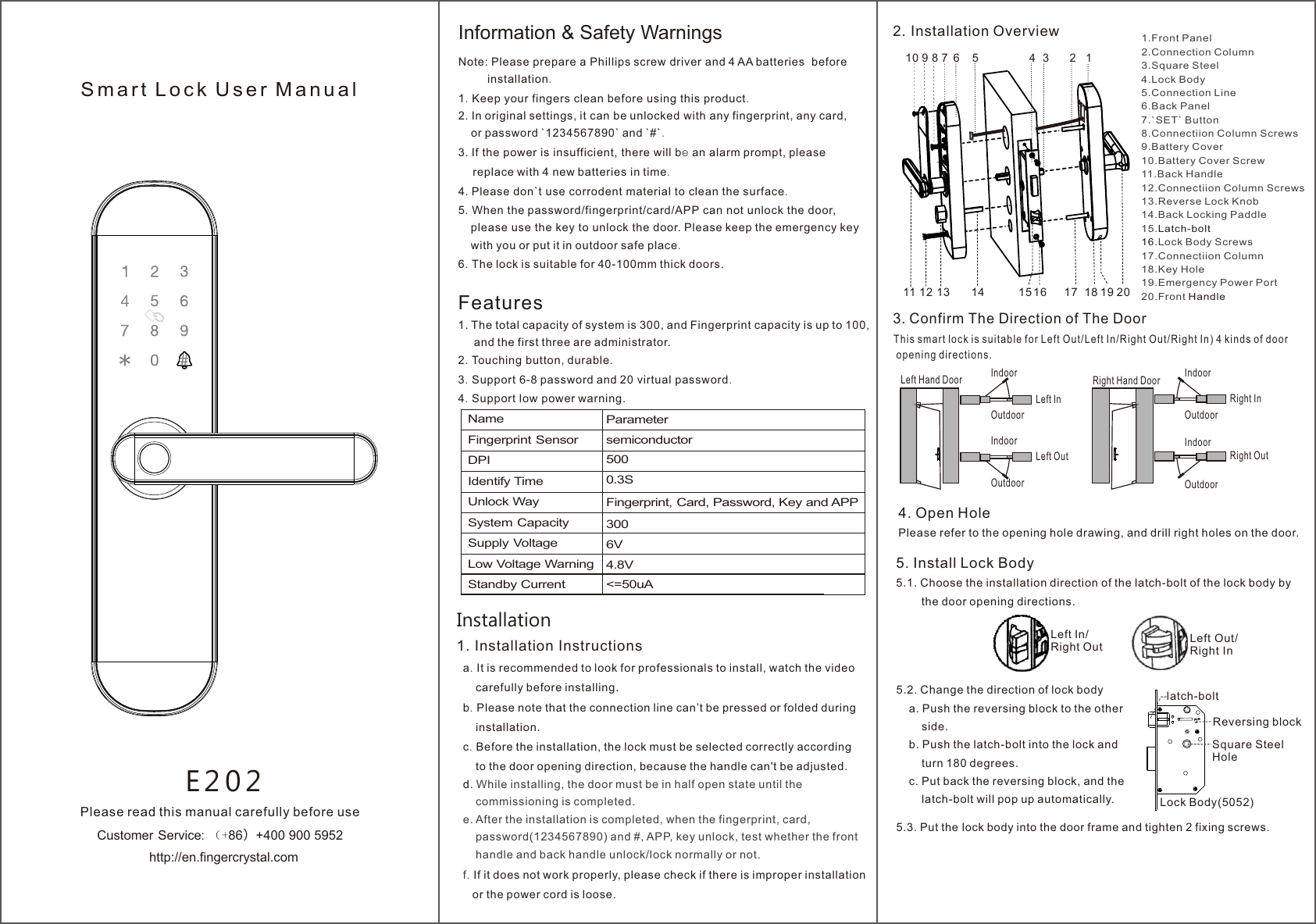
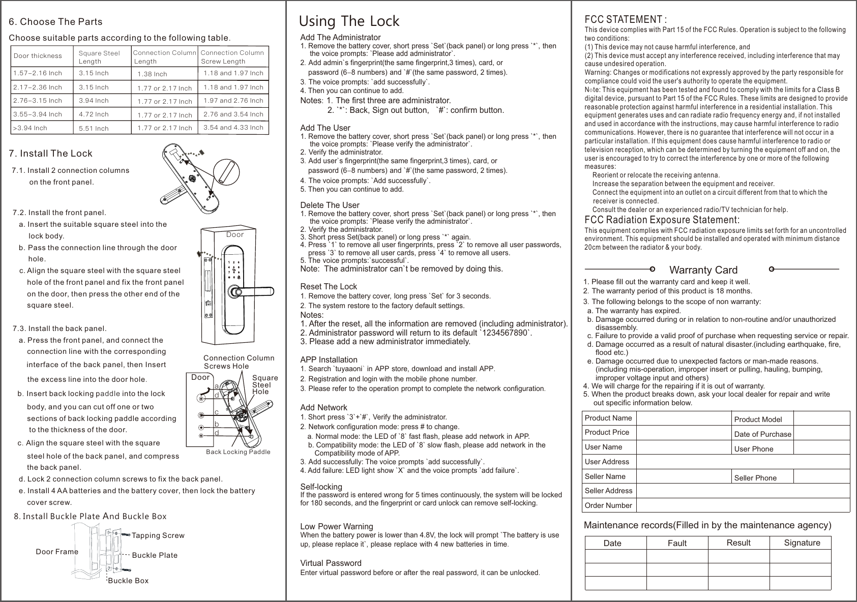
Fingerchip Intelligent Technology E202 Smart lock User Manual 1

Shenzhen Fingerchip Intelligent Technology Co., Ltd. Smart lock 1

User Manual

Note: Please prepare a Phillips screw driver and 4 AA batteries  before         installation.1. Keep your fingers clean before using this product.2. In original settings, it can be unlocked with any fingerprint, any card,    or password `1234567890` and `#`.3. If the power is insufficient, there will be an alarm prompt, please     replace with 4 new batteries in time.4. Please don`t use corrodent material to clean the surface.5. When the password/fingerprint/card/APP can not unlock the door,     please use the key to unlock the door. Please keep the emergency key    with you or put it in outdoor safe place.6. The lock is suitable for 40-100mm thick doors. Features1. The total capacity of system is 300, and Fingerprint capacity is up to 100,     and the first three are administrator.2. Touching button, durable.3. Support 6-8 password and 20 virtual password.4. Support low power warning.E 2 0 2S m a r t  L o c k  U s e r  M a n u a lPlease read this manual carefully before usehttp://en.fingercrystal.comCustomer Service: (+86)+400 900 5952 Information & Safety WarningsNameFingerprint SensorDPIIdentify TimeUnlock WaySystem CapacitySupply VoltageLow Voltage WarningStandby CurrentParametersemiconductor5000.3SFingerprint, Card, Password, Key and APP3006V 4.8V<=50uAInstallation1. Installation Instructions  a.  It is recommended to look for professionals to install, watch the video      carefully before installing.  b. Please note that the connection line can’t be pressed or folded during       installation.  c. Before the installation, the lock must be selected correctly according      to the door opening direction, because the handle can't be adjusted.  d. While installing, the door must be in half open state until the       commissioning is completed.  e. After the installation is completed, when the fingerprint, card,      password(1234567890) and #, APP, key unlock, test whether the front       handle and back handle unlock/lock normally or not.. If it does not work properly, please check if there is improper installation  f     or the power cord is loose. 123456810 9191716 1814131211 2072. Installation Overview 1.Front Panel2.Connection Column3.Square Steel4.Lock Body5.Connection Line6.Back Panel7.`SET` Button8.Connectiion Column Screws9.Battery Cover10.Battery Cover Screw11.Back Handle12.Connectiion Column Screws13.Reverse Lock Knob14.Back Locking Paddle15.Latch-bolt16.Lock Body Screws17.Connectiion Column18.Key Hole19.Emergency Power Port20.Front Handle15Left Hand Door IndoorLeft InOutdoorLeft OutRight InRight OutRight Hand Door3 Confirm The Direction of The Door.                Th i s smart lock is suitable for Le f t Out/Left In/Right Ou t / R i g h t In) 4 ki n d s of door        op e n i n g directions.  IndoorOutdoorIndoorOutdoorIndoorOutdoor4. Open HolePlease refer to the opening hole drawing, and drill right holes on the door.Left Out/Right InLeft In/Right Out5. Install Lock Body   5.1. Choose the installation direction of the latch-bolt of the lock body by        the door opening directions. 5.2. Change the direction of lock body    a. Push the reversing block to the other        side.    b. Push the latch-bolt into the lock and         turn 180 degrees.     c. Put back the reversing block, and the        latch-bolt will pop up automatically.Reversing blocklatch-boltLock Body(5052) 5.3. Put the lock body into the door frame and tighten 2 fixing screws.             Square Steel Hole
DoorWarranty Card1. Please fill out the warranty card and keep it well.2. The warranty period of this product is 18 months.3. The following belongs to the scope of non warranty:  a. The warranty has expired.   b. Damage occurred during or in relation to non-routine and/or unauthorized      disassembly.  c. Failure to provide a valid proof of purchase when requesting service or repair.  d. Damage occurred as a result of natural disaster.(including earthquake, fire,       flood etc.)  e. Damage occurred due to unexpected factors or man-made reasons.      (including mis-operation, improper insert or pulling, hauling, bumping,       improper voltage input and others)4. We will charge for the repairing if it is out of warranty.5. When the product breaks down, ask your local dealer for repair and write     out specific information below.Product NameProduct PriceUser NameUser AddressSeller NameSeller AddressOrder Number7.2. Install the front panel.   a. Insert the suitable square steel into the        lock body.   b. Pass the connection line through the door       hole.   c. Align the square steel with the square steel        hole of the front panel and fix the front panel        on the door, then press the other end of the        square steel.7.3. Install the back panel.   a. Press the front panel, and connect the       connection line with the corresponding      interface of the back panel, then Insert      the excess line into the door hole.  b. Insert back locking p into the lock addle        body, and you can cut off one or two         sections of back locking paddle according         to the thickness of the door.  c. Align the square steel with the square        steel hole of the back panel, and compress        the back panel.   d. Lock 2 connection column screws to fix the back panel.   e. Install 4 AA batteries and the battery cover, then lock the battery        cover screw.Add The Administrator1. Remove the battery cover, short press `Set`(back panel) or long press `*`, then    the voice prompts: `Please add administrator`.2. Add admin`s fingerprint(the same fingerprint,3 times), card, or     password (6-8 numbers) and `#`(the same password, 2 times).3. The voice prompts: `add successfully`. 4. Then you can continue to add.Notes: 1. The first three are administrator.            2. `*`: Back, Sign out button,   `#`: confirm button.Add The User1. Remove the battery cover, short press `Set`(back panel) or long press `*`, then     the voice prompts: `Please verify the administrator`.2. Verify the administrator.3. Add user`s fingerprint(the same fingerprint,3 times), card, or     password (6-8 numbers) and `#`(the same password, 2 times).4. The voice prompts: `Add successfully`. 5. Then you can continue to add.Delete The User1. Remove the battery cover, short press `Set`(back panel) or long press `*`, then      the voice prompts: `Please verify the administrator`.2. Verify the administrator.3. Short press Set(back panel) or long press `*` again.4. Press `1` to remove all user fingerprints, press `2` to remove all user passwords,     press `3` to remove all user cards, press `4` to remove all users.5. The voice prompts:`successful`.Note:  The administrator can`t be removed by doing this. Reset The Lock1. Remove the battery cover, long press `Set` for 3 seconds.2. The system restore to the factory default settings.Notes: 1. After the reset, all the information are removed (including administrator).2. Administrator password will return to its default `1234567890`.3. Please add a new administrator immediately.APP Installation1. Search `tuyaaoni` in APP store, download and install APP.2. Registration and login with the mobile phone number. 3. Please refer to the operation prompt to complete the network configuration.Add Network1. Short press `3`+`#`, Verify the administrator.2. Network configuration mode: press # to change.    a. Normal mode: the LED of `8` fast flash, please add network in APP.    b. Compatibility mode: the LED of `8` slow flash, please add network in the        Compatibility mode of APP.3. Add successfully: The voice prompts `add successfully`.4. Add failure: LED light show `X` and the voice prompts `add failure`.Self-lockingIf the password is entered wrong for 5 times continuously, the system will be lockedfor 180 seconds, and the fingerprint or card unlock can remove self-locking. Low Power WarningWhen the battery power is lower than 4.8V, the lock will prompt `The battery is use up, please replace it`, please replace with 4 new batteries in time.Virtual PasswordEnter virtual password before or after the real password, it can be unlocked.Using The Lock4.72 Inch      1.77 or 2.17 Inch  2.76 and 3.54 Inch3.55-3.94 Inch5.51 Inch      1.77 or 2.17 Inch  3.54 and 4.33 Inch>3.94 Inch6. Choose The Parts Choose suitable parts according to the following table. Door thickness           Square Steel   Connection Column 3.15 Inch        1.38 Inch 1.18 and 1.97 Inch3.15 Inch       3.94 Inch       Connection Column1.77 or 2.17 Inch  1.18 and 1.97 Inch1.77 or 2.17 Inch 1.57-2.16 Inch2.17-2.36 Inch2.76-3.15 Inch 1.97 and 2.76 InchLength Length Screw Length7.1. Install 2 connection columns         on the front panel. 7. Install The Lock 8. Install Buckle Plate And Buckle BoxTapping ScrewBuckle PlateBuckle BoxDoor FrameBack Locking PaddleabcddConnection Column DoorScrews HoleSquare Steel HoleFCC STATEMENT :This device complies with Part 15 of the FCC Rules. Operation is subject to the followingtwo conditions:(1) This device may not cause harmful interference, and(2) This device must accept any interference received, including interference that maycause undesired operation.Warning: Changes or modifications not expressly approved by the party responsible forcompliance could void the user's authority to operate the equipment.Note: This equipment has been tested and found to comply with the limits for a Class Bdigital device, pursuant to Part 15 of the FCC Rules. These limits are designed to providereasonable protection against harmful interference in a residential installation. Thisequipment generates uses and can radiate radio frequency energy and, if not installedand used in accordance with the instructions, may cause harmful interference to radiocommunications. However, there is no guarantee that interference will not occur in aparticular installation. If this equipment does cause harmful interference to radio ortelevision reception, which can be determined by turning the equipment off and on, theuser is encouraged to try to correct the interference by one or more of the followingmeasures: Reorient or relocate the receiving antenna. Increase the separation between the equipment and receiver. Connect the equipment into an outlet on a circuit different from that to which the     receiver is connected. Consult the dealer or an experienced radio/TV technician for help.FCC Radiation Exposure Statement:This equipment complies with FCC radiation exposure limits set forth for an uncontrolled environment. This equipment should be installed and operated with minimum distance 20cm between the radiator & your body.Product ModelDate of PurchaseUser PhoneSeller PhoneMaintenance records(Filled in by the maintenance agency)Date Fault Result Signature

Navigation menu