Flir BelgiumBA CCTR Low-power (unlicensed) wireless device for leisure User Manual 81276 1 GSeries RefMan
Raymarine UK Ltd. Low-power (unlicensed) wireless device for leisure 81276 1 GSeries RefMan
Contents
Gseries Reference Part 2

G-Series Reference Manual 112
9.1 Disclaimer
For disclaimer see
page 218
.
9.2 Weather application pre-requisites
Before you can use the weather application you need to:
• Obtain a Sirius ID number. (For full details, see the Sirius Instal-
lation handbook.)
• Customize a page set to include a weather application.
• Specify the weather elements that you wish to display.
• For the G-Series system to display weather data, it must be
connected to an SR100 Sirius Receiver which is supplying the
appropriate data.
• For your vessel to be displayed and for weather reports to be
available at your position, you need a fix for your boat’s position
and be within range of Sirius satellites.
For further information on installing and commissioning a weather
receiver, see the SR100 Weather Receiver Installation Guide.
Creating a weather window
A weather application window is not included in the pre-configured
page sets. You therefore need to customize a page set to include
one. For information about how to do that, see Selecting an appli-
cation page on page 26.
9.3 Weather application setup
With a weather window active, the Weather Setup Menu is avail-
able from the system Setup menu.
To open the Weather Setup Menu
1. With a weather window active, press the MENU button.
2. Select Weather Setup menu.
Specifying meteorological elements
You can choose to view textual weather reports or animated graph-
ics for specific weather element.
To specify meteorological elements
1. Make a weather window active.
2. Press the DISPLAY GRAPHICS softkey.
3. Select a weather element and make the appropriate setting for
each element you are interested in.
4. Press OK.
FUNCTION OPTION
Sirius Weather User ID
Details the Weather ID obtained from Sirius
and keyed in on your display.
(as advised)
Wind Symbol
Graphic used for wind symbol
Arrow
Barb
Marine Watchbox Alerts
Enables alert when watchbox is issued.
OFF
50nm
150nm
300nm
500nm
ALL
113 Chapter 9: Sirius Weather (US only)
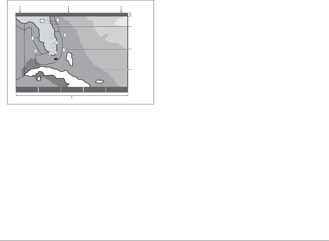
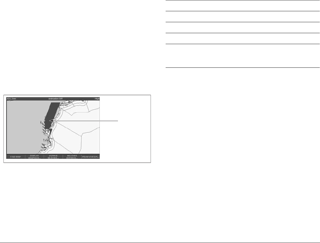
9.4 The weather display
The main features of the weather display are shown below.
Note: Time shown can be either for the time of latest data or
animation time/date, as appropriate.
9.5 Moving around the weather map
When you open the weather application, a world map is displayed.
Use the cursor to move around the map and the range button to
zoom in and out.
To re-centre the map on your boat, use the FIND SHIP softkey.
9.6 Placing waypoints
The waypoint button operates as normal when a weather window is
active, but you need to make a radar or chart window active to see
the waypoints.
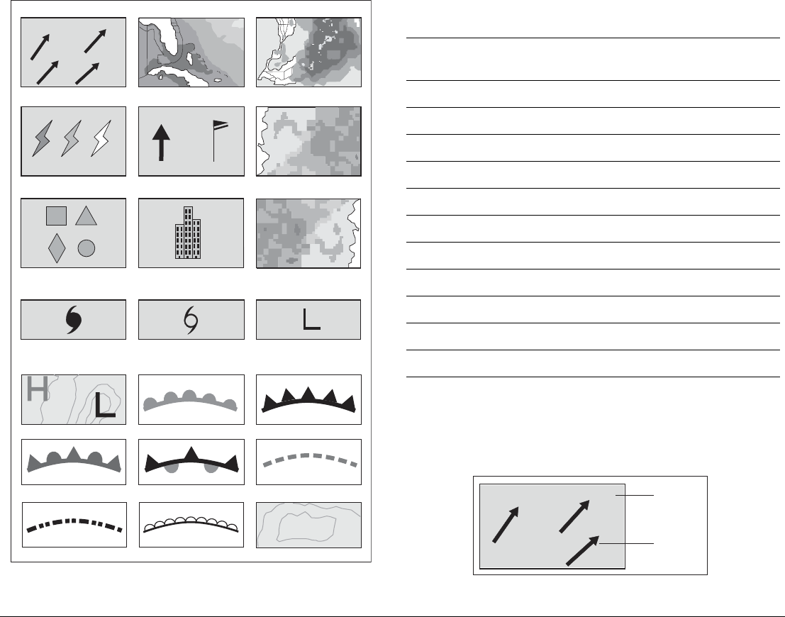
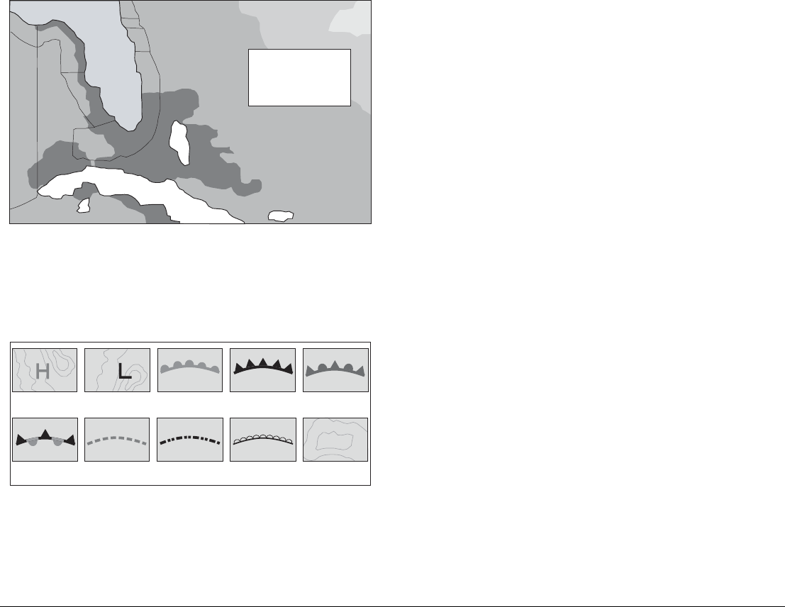
9.7 Weather symbols
The following table summarizes the weather symbols used by the
G-Series system. The section after it gives more information about
each.
Many symbols have additional data associated with them. If this is
the case, the object window will contain the text “OK for more info”.
To display additional data for meteorological objects
1. Highlight the object.
2. If a pop-up indicates that additional data is available, press OK
to see it.
FIND SHIP DISPLAY
GRAPHICS...
ANIMATE
WEATHER...
WEATHER
REPORTS... PRESENTATION...
2400 nm Medium
Marine
zone
Range Animation time/data
Status
bar
Weather soft keys
D8564_1
Signal strength
Wave
heights
Surface
observation
stations
12:00 22/11
G-Series Reference Manual 114
Precipitation (NOWRad)
NOWRad displays the type and level of precipitation:
Storm Cast
Storm cast arrows indicate the direction and speed of a storm.
Waves (blues) Canadian radar (Dark greens-yellow)
Storm cast
Cities (grey)
Surface observation stations (pink)
Lightning Wind Sea surface temperature
( green-yellow-orange)
Weather symbols
Surface pressure
26
22
22
24
Squall line (red)
D8613_1
Hurricane (Category 1-5) Tropical storm Tropical disturbance,
tropical depression
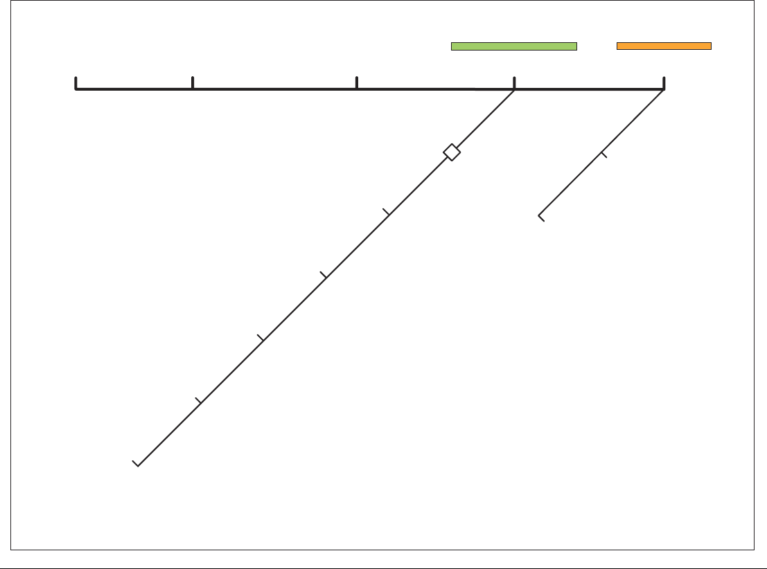
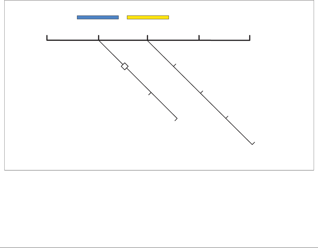
Storm Tracks symbols
Or
1012
High / low pressure (blue & red) Cold front (blue)Warm front (red)
Occluded front (purple) Stationary front (red-blue) Trough (brown)
Isobars (grey)
1010
Dry line (red)
NOWRad (green-yellow-red)
Snow (Blues),Mixture (Pinks)
Color Precipitation
type Intensity (dBz)
Light green Rain 15-19
Medium green Rain 20-29
Dark green Rain 30-39
Yellow Rain 40-44
Orange Rain 45-49
Light red Rain 50-54
Dark red Rain 55 +
Light blue Snow 5-19
Dark blue Snow 20 +
Light pink Mixed 5-19
Dark pink Mixed 20 +
Direction
of storm
Speed of
storm
26
22
24
D8926_1
115 Chapter 9: Sirius Weather (US only)
Sea surface
temperature
(SST)
The temperature
range of the sea sur-
face is indicated by
shading, from low
temperatures to
higher temperatures
through blue-green-
yellow-orange-red.
Canadian radar
Canadian radar shows the intensity of precipitation for Canada.
Unlike NOWRad, Canadian radar does not show the precipitation
type.
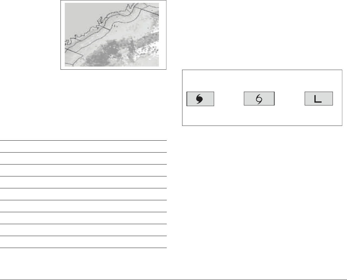
Tracking storms
You can use the STORM TRACK function to monitor significant
storms in your area. These include tropical disturbances, depres-
sions, storms and cyclones, hurricanes, typhoons and super-
typhoons.
The G-Series system displays the path the storm has taken, its cur-
rent and forecast position, the wind radii (for its current position
only), and its current direction and speed of travel.
Tropical storm data
Tropical storm data can be displayed for a selected storm. The data
includes:
• The storm’s name, type, date and time.
• The position, direction and speed of travel of the storm.
• The pressure and maximum wind speed and gusts.
Color Intensity (mm/hr)
Transparent 0.00-0.20
Light green 0.21-1.00
Medium green 1.01-4.00
Dark green 4.01-12.00
Yellow 12.01-24.00
Orange 24.01-50.00
Light red 50.01-100
Dark red 100.01 +
D8570_1
Hurricane
(Category 1-5)
Tropical storm Tropical disturbance,
tropical depression
Storm Tracks symbols
These symbols are displayed on screen in three different colours:
Grey - historical, Red - current, Orange - forecast
Move the cursor over the symbol for additional information.
D8931_1
G-Series Reference Manual 116
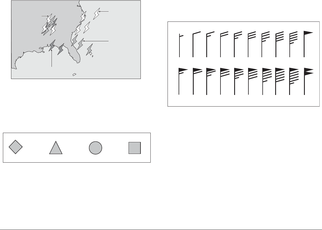
Lightning
The system puts a lightning symbol at every cloud-to-ground strike
recorded within the last 5, 10 and 15 minutes.
Surface observation stations
You can view current or historical weather data at surface observa-
tion stations.
City forecasts
The Cities option gives you access to details of city weather fore-
casts. Forecasts for up to three days may be available.
Wind
This option displays the current wind direction and magnitude. You
can choose (using the Weather Setup Menu) to display the wind
symbol as either an arrow or a wind barb. Wind arrows give an indi-
cation of wind speed - the larger the arrow the stronger the wind.
Wind barbs give a more precise representation of wind speed:
Waves
This option gives you wave period, wave direction and wave height
data.
Strike recorded in
last 0 - 5 minutes
Strike recorded in
last 5 - 10 minutes
More recent strikes
overlay older ones
Strike recorded in
last 10 - 15 minutes
D8575_1
Lightning Strikes
Buoy Station C - MAN WSI NWS
All surface observations stations are represented by a pink symbol:
D8975-1
3-7 kts 8-12 kts 13-17 kts 18-22 kts 23-27 kts 28-32 kts 33-37 kts 38-42 kts 43-47 kts 48-52 kts
53-57 kts 78-82 kts73-77 kts68-72 kts63-67 kts58-62 kts 88-92 kts83-87 kts 98-102 kts93-97 kts
Wind speed symbols
D8571_1
etc.
117 Chapter 9: Sirius Weather (US only)
Wave height is displayed in 16 levels:
Surface pressure
This option shows surface pressure data using standard meteoro-
logical symbols.
Waves shown in
16 shades of colour from:
Reds - Highest waves
Greens - Intermediate waves
Blues - Lowest waves
Cuba
Florida
Wave height ranges
D8603_1
D8651_1
Squall line (red)
High pressure
(blue)
High pressure
(red) Cold front (blue)Warm front (red) Occluded front
(purple)
Stationary front
(red-blue)
Trough (brown) Isobars (grey)
1012
1010
Dry line (brown)
G-Series Reference Manual 118
9.8 Weather toolbar
Options available under the default weather toolbar are summarized in the following two diagrams.
FIND SHIP DISPLAY GRAPHICS ANIMATE WEATHER WEATHER REPORTS PRESENTATION
Weather reports pop-up
Forecast at cursor/ship
Tropical statements
Marine warnings
Marine zone forecasts
Watchbox warnings
Watchbox show/hide
Marine zone show/hide
D10566-1
119 Chapter 9: Sirius Weather (US only)
9.9 Viewing data for a specific
position
It is possible to display the sea temperature, wind speed and direc-
tion, wave height, precipitation intensity and type for a location
specified by you. The marine zone is also shown.
To view data for a specific position
1. Move the cursor to the required position.
2. Press OK.
FIND SHIP DISPLAY
GRAPHICS
ANIMATE
WEATHER
Forecast win/wav/pres
Wave Direction
Wave Period
WEATHER
REPORTS PRESENTATION
Animate type forecast/n-rad
Animate on/off
Pause on/off
Weather graphics pop-up
D10566-1
G-Series Reference Manual 120
9.10 Animated weather graphics
The animated weather feature allows you to view an animation
from the current time for:
• The forecast for wind and wave activity or surface pressure.
• The weather radar history loop (NOWRad).
You cannot display information by moving the cursor over a symbol
when animation is running.
The range and trackpad controls do however remain operable, pro-
vided the PAUSE option has not been selected. Ranging or
panning causes the animation to restart.
The animation stops if you press any of the ACTIVE, PAGE, DATA,
WPS/MOB, or MENU buttons, or if you close the window containing
the animation.
To set up an animated weather graphic
1. Press the ANIMATE WEATHER softkey.
2. Toggle to the required setting on the ANIMATE TYPE softkey.
3. Toggle to the required option on the FORECAST softkey (wind,
wave or surface pressure).
To run an animation
1. Press the ANIMATE WEATHER softkey.
2. Toggle to ON with the ANIMATE softkey.
The status bar indicates the time-frame displayed. The weather
radar history provides up to eight images of data covering the last
two hours, at 15-minute intervals.
To pause an animation
1. Press the PAUSE softkey.
9.11 Viewing weather reports
The following weather reports are available:
• Tropical statements.
• Marine warnings.
• Marine zone forecasts.
• Watchbox warnings.
Each report type may contain several bulletins; the window can be
scrolled to view all the data.
To view weather reports
1. Press the WEATHER REPORTS softkey.
2. Press the appropriate softkey for the type of report you want.
3. If available, select the relevant option on the FORECAST AT
softkey (ship or cursor).
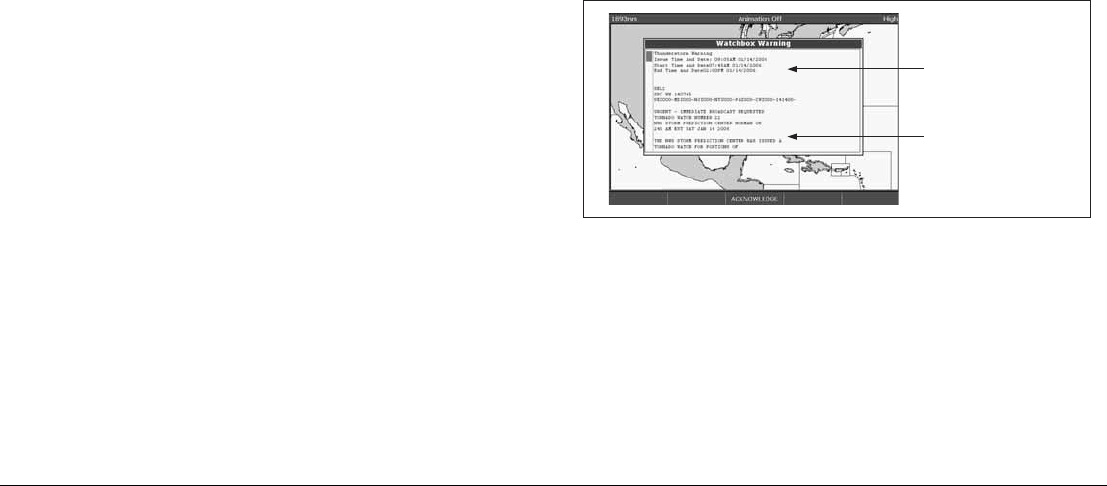
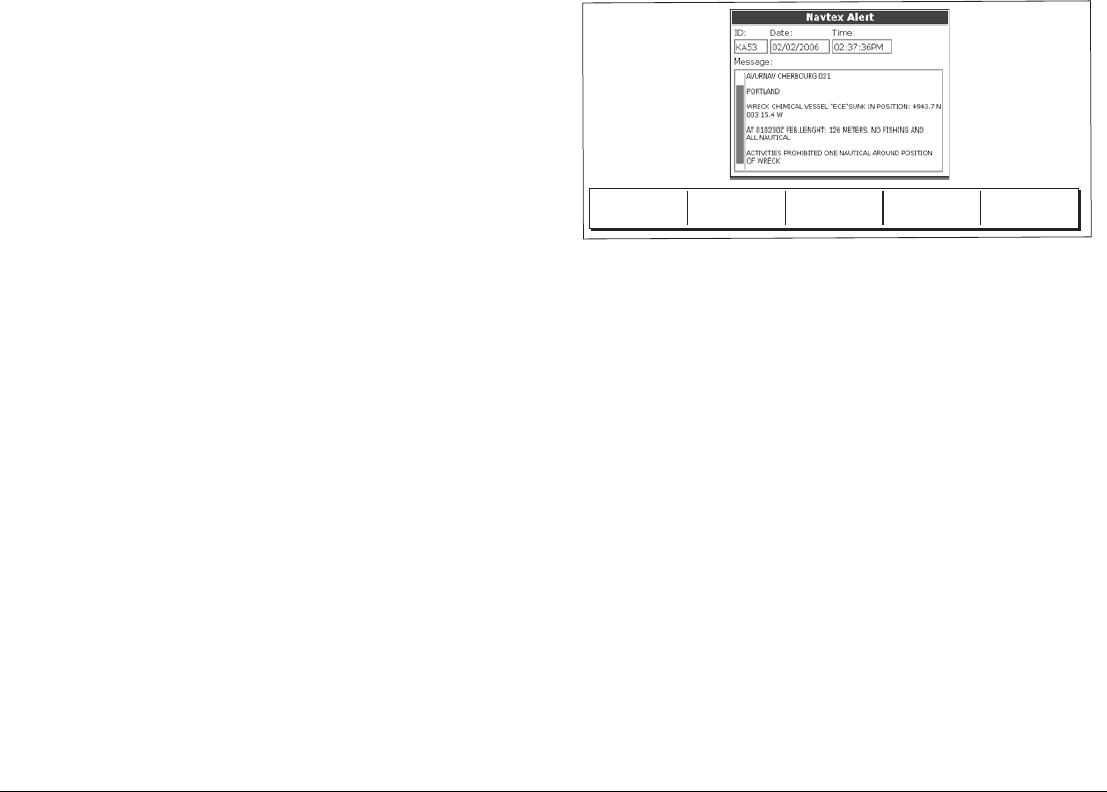
Watchbox warnings
When a tornado or thunderstorm warning is received, the system
generates a watchbox alert:
Use the trackpad or rotary control to scroll through the report.
You can set the range for the watchbox alert to: OFF; 50; 150; 300;
500 and ALL using the weather setup menu. Any watchbox outside
of the selected range will not trigger the alarm. (Units vary accord-
ing to the configuration of your system.)
D8606_1
Warning type and
period for which
warning is valid
Watchbox report
text
121 Chapter 9: Sirius Weather (US only)
You can switch off the marine watchbox alert (using the Weather
Setup Menu, see page 112) or set the watchbox status to hide.
Reports continue to be added to the database, irrespective of the
alert and show/hide status.
To clear a watchbox alert
1. Press ACKNOWLEDGE.
The alert is removed from the display but you can still see the
watchbox warning by using the Weather Reports softkeys.
Displaying marine watchboxes
When the marine watchboxes feature is ON (default), any regions
for which a watchbox is valid are highlighted on the weather map as
a red polygon.
To show or hide watchboxes
1. Press the PRESENTATION softkey.
2. Toggle to the appropriate setting on the WATCHBOX softkey.
To display watchbox data
1. Highlight the watchbox.
2. Press OK to display the Object Info pop-up screen.
3. Press OK again to display the watchbox data.
9.12 Troubleshooting
D8608_1
Watchbox alert
warning area
Problem Reason
Boat symbol not displayed No position fix
FIND SHIP softkey greyed-out No position fix
Boat symbol drawn as a solid circle No heading or COG available
‘No Connection’ message is displayed
in the status bar
No signal received from SR100;
check cabling and that SR100 is
powered.

G-Series Reference Manual 122

10
Chapter 10: Navtex
You can use the G-Series system to view marine safety information (including weather forecasts and marine
warnings) if you have a Navtex integrated receiver connected to your system.
Major areas of coverage include the Mediterranean Sea, The North Sea, coastal areas around Japan and
areas around the North American continent.
Chapter contents
• 10.1 Setting up Navtex on page 124
• 10.2 Selecting message alert categories on page 124
• 10.3 The Navtex message window on page 124
• 10.4 Managing Navtex messages on page 124
G-Series Reference Manual 124
10.1 Setting up Navtex
Before you are able to view Navtex messages you need to:
• Specify the baud rate of your Navtex receiver.
• Enable the appropriate category of Navtex messaging (see
page 125).
10.2 Selecting message alert
categories
On initial power up, the system provides alerts for all message cat-
egories listed in the Navtex Alert Menu. You can switch off any
category except Navigation Warnings (Category A), Meteorological
Warnings (Category B) and Search and Rescue information (Cate-
gory D).
To select the message alert categories
1. Press MENU to open the Setup menu.
2. Select Navtex Messages and open the Navtex Message List.
3. Press the SETUP ALERTS softkey.
4. Select the appropriate category and toggle its status to the
required setting.
10.3 The Navtex message window
Once correctly connected to the Navtex unit, the system will display
messages it receives from within your chosen categories:
When you receive a message, the toolbar gives you the option to
erase or save the message as appropriate. The G-Series system
can save up to 100 Navtex messages. Once this capacity is
reached, it starts to overwrite the oldest messages with newer
ones.
To view saved messages
1. Press MENU to open the Setup menu.
2. Select Navtex messages.
3. Select the appropriate message from the list.
The message text is displayed in the right-hand column. Scroll
through it to see the complete text.
You also have the option to sort the message list by date, station or
category, erase a message, or set up the message alerts.
10.4 Managing Navtex messages
Management options for Navtex messages allow you to:
D8870_1
ERASE MESSAGE SAVE MESSAGE

125 Chapter 10: Navtex
• Select categories for which the G-Series system will show
alerts.
• Erase messages.
• Sort the message list.
Sorting the message list
By default the message list sorts by the date and time the message
was received (DATE) with the most recent message at the top. If
required, you can sort the list by station identifier (STN) or by mes-
sage category (CAT).
To sort the message list
1. Press MENU to open the Setup menu.
1. Select Navtex Messages and open the Navtex Message List.
2. Toggle to your preferred sorting method on the SORT LIST
softkey.

G-Series Reference Manual 126

11
Chapter 11: Radar
The G-Series can be used with digital radar scanners. Digital scanners offer:
• Improved target definition.
• Full-color image.
• Scan-to-scan.
• SuperHD option. Super HD effectively increases the transmitter power by a factor of at least two, and re-
duces the beamwidth by a similar amount.
• Dual-range operation.
• Simultaneous operation of two radar scanners.
Chapter contents
• 11.1 Radar setup on page 128
• 11.2 Controlling power to the scanners on page 130
• 11.3 Radar range and image quality on page 131
• 11.4 Radar window overview on page 134
• 11.5 Using waypoints with the radar on page 135
• 11.6 Radar display options on page 136
• 11.7 Tuning the radar display: GAIN on page 140
• 11.8 Tuning the radar display: ENHANCE ECHOES on page 143
• 11.9 Radar range on page 144
• 11.10 Measuring distance, range and bearing on page 145
• 11.11 Using radar to track objects on page 150

G-Series Reference Manual 128
11.1 Radar setup
The Radar Setup Menu lets you customize the way the radar operates. Changes you make in this menu are kept when you remove power
from the G-Series system.
.
Note: The radar needs to be receiving heading and position data
for full functionality.
Select scanner
Selects which scanner is displayed in the active radar window.
Scanner setup
The scanner setup option lets you customize various aspects of the
scanner’s behavior.
Dual range
If dual range is set to on, the system allows you to view two ranges
simultaneously in one window.
Short range gives you a maximum range of 3 nautical miles; long
range provides standard ranges.
When dual range is enabled, chart overlay and synchroniza-
tion functions are disabled. If you already have chart overlay
or synchronization turned on, dual range is not available.
Tune
The tune function is used to fine-tune the scanner’s receiver for
maximum target returns on the display.
Auto mode: recommended
In AUTO mode, the radar tunes itself automatically on all range
scales.
This is the default mode and it is recommended that you leave the
tune function in auto mode to ensure that the radar receiver is
always tuned to receive the maximum signal.
Radar Setup > Select Scanner
Scanner Setup > Dual Range
Color Palette
EBL Reference Tune
Timed Transmit Sea Clutter Curve
Transmit Period Parking Offset
Standby Period Scanner Size
Bearing Alignment
Radar Advanced Setup
MENU

129 Chapter 11: Radar
Manual (MAN) mode
If you do set the tune function to MANUAL, you will need to adjust it
about 10 minutes after you have turned on the radar, since the
required setting will change after the magnetron has warmed up.
Adjust the control to obtain the maximum signal strength (indicated
by the eight-step horizontal bar). If you cannot tune the radar suc-
cessfully, refer to the Installation Guide.
Sea clutter curve
Adjust the system’s sensitivity to sea clutter. The steepest setting is
1 and the shallowest is 8. The default setting is 4.
Parking offset
The default parking offset is 0 degrees: the scanner aligns with the
pedestal, facing forwards.
With parking offset selected you can use the rotary controller to
adjust the parking offset from 0 to 358 degrees in steps of two
degrees.
This setting change is only available when the digital radar is set to
Off or Standby. The changes you make are applied at the end of the
next transmit cycle.
To open the radar setup menu
1. Make a radar application window active.
2. Press the MENU button.
Edit name
The edit name softkey is available when the radar setup menu is
open. This option allows you to name scanners. The default names
are 1 for the first scanner and 2 for the second scanner if there is
one. Names can be up to five characters long, and are displayed on
the title bar.
Radar alarms
For information about the radar-specific alarms you can configure,
see Alarm Setup Menu on page 194.
Note: Until you are familiar with interpreting the radar display, take
every opportunity to compare the radar display with your
physical surroundings. Note the location of boats, buoys and
coastal structures and their corresponding echoes on the
radar display. Practice harbor and coastal navigation during
daylight hours and in clear weather conditions.
G-Series Reference Manual 130
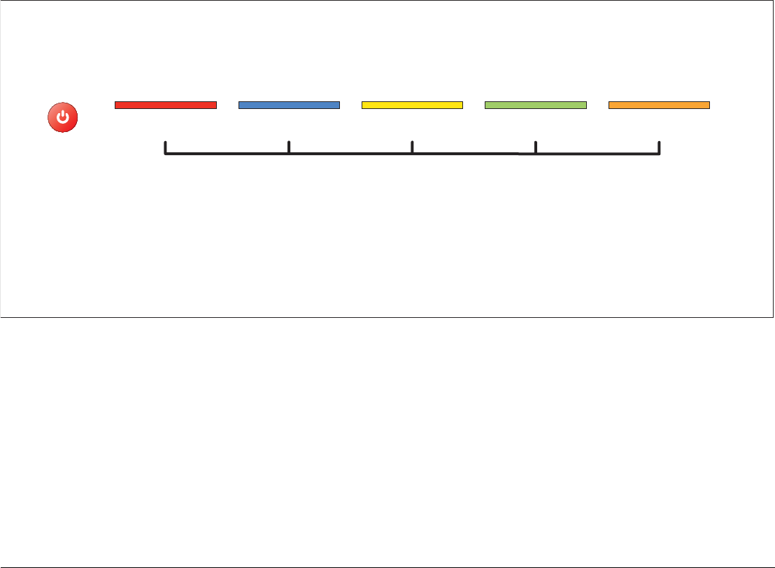
11.2 Controlling power to the scanners
You control power to the radar scanners from the power control toolbar, which you open with the power button on the G-Series keyboard:
There are three power states for the radar scanners:
• Off.
• On and in standby: powered up and ready to transmit.
• On and in transmit (TX): rotating and transmitting.
The default power mode is on and in standby.
To change scanner power states
1. Press the power button.
2. Toggle to your desired power state on RADAR 1 or RADAR 2
as appropriate.
You can turn the radar scanners off even if there is no display, or if
the display is blank for any reason. In this situation, a message on
the keyboard LCD screen prompts you.
To switch scanners off when the monitor is blank
1. Press the power button.
A prompt on the keyboard LCD says “To switch radars off
press power”.
2. Press the power button.
PWR
RADAR 1
TX STBY
RADAR 1
ON OFF
RADAR 2
TX STBY
RADAR 2
ON OFF
MONITOR
CONTROLS
D10569-1
131 Chapter 11: Radar
Radar status
The following table summarizes the various scanner states and
associated status icons.
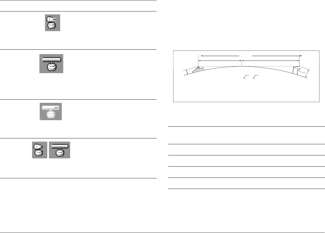
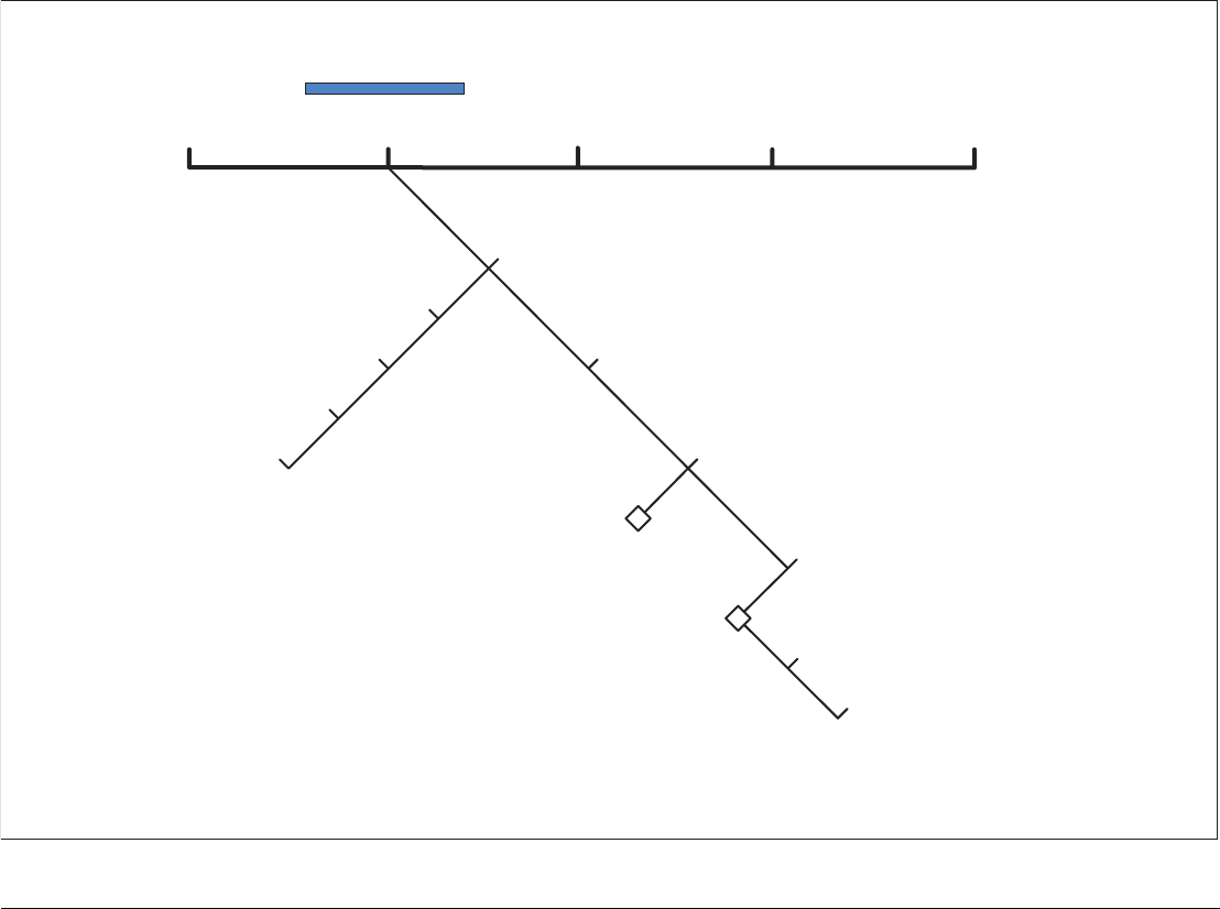
11.3 Radar range and image quality
Radar operates by transmitting radio pulses, then detecting the
reflections as the pulses bounce back from objects within radar
range. The reflections are processed and displayed on-screen as
‘echoes’.
Range
Radar range is limited by the height of your scanner and the height
of the target, as illustrated below:
The table below gives the approximate range for various antenna
and target heights.
Image quality
Not all radar echoes are produced by valid targets. Spurious ech-
oes may be caused by:
Status Icon Description
Transmit
(TX)
Scanner on and transmitting.
This is the usual mode of operation.
Standby
(STDBY)
Scanner powered on but not transmit-
ting; antenna not rotating.
This is a power-save mode used when
radar is not needed for short periods.
When you return to transmit mode, the
magnetron does not need to warm up.
This is the default mode.
Off
Scanner powered off.
When radar is not required.
Timed
transmit
Scanner switches between on/trans-
mitting & standby mode.
Power save mode when constant use of
radar not required. To set up this option,
see page 131
D7440-1
(Rotating icon)
D6894-2
(static icon)
D7441-1
(grayed-out icon)
D7442-1
(rotating/static icon)
Antenna height
(m)
Object height
(m)
Range
(nm)
3 3 7.7
3 10 10.9
5 3 8.8
5 10 12
a1a2
Earth
h
H
Cliff
Radar
D1643-3
Rmax
Rmax = 2.23 ( h + H )
Rmax
h
H
maximum radar range
radar antenna height
target height
in nautical miles
in metres
in metres
Rmax = radar horizon of antenna (a1) + radar horizon of target (a2)
G-Series Reference Manual 132
• Side lobes
• Indirect echoes
• Multiple echoes
• Blind sectors
• Sea, rain or snow clutter
• Interference
Through observation, practice, and experience, you can generally
detect these conditions very quickly and use the radar controls to
minimize them.
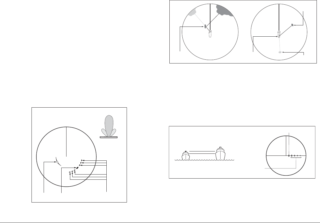
Side lobes
Side lobe patterns are produced by small amounts of energy from
the transmitted pulses that are radiated outside the narrow main
beam.
The effects of side lobes are most noticeable with targets at short
range (normally below 3 nm) and with large objects. Side lobe ech-
oes form either arcs on the radar screen similar to range rings, or a
series of echoes forming a broken arc.
Indirect echoes
There are several types of indirect echoes, or ‘ghost’ images.
These sometimes have the appearance of true echoes, but in gen-
eral they are intermittent and poorly defined.
Multiple echoes
Multiple echoes are uncommon but can occur if there is a large
object with a wide vertical surface at a comparatively short range.
The transmitted signal bounces between the object and your own
vessel, producing multiple echoes. The false echoes are displayed
beyond the range of the true target echo, but on the same bearing.
Blind sectors
Obstructions such as funnels and masts near the radar antenna
can obstruct the radar beam and cause radar shadows or ‘blind
sectors’.
True echo Side echoes
Main lobe
Antenna
Arc
Side
lobe
Side
lobe
D1638-4
False echo
Passing
ship
True echo
D1641-4
True echo
False echo
Mast
or funnel
D1642-3
True echo
Multiple echoes
133 Chapter 11: Radar
If the obstruction is relatively narrow, there will be a reduction of the
beam intensity, though not necessarily a complete cut-off. However,
with wider obstructions there can be a total loss of signal in the
shadow area. There might also be multiple echoes which extend
behind the obstruction.
Blind sector effects can normally be minimized by careful selection
of the scanner site prior to installation.
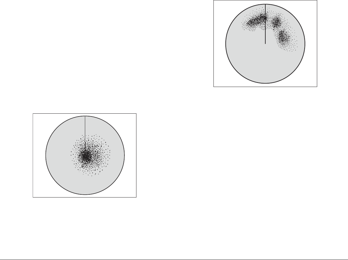
Sea clutter
Radar returns from waves around the vessel can clutter the centre
of the radar picture, making it difficult to detect real targets. Such
‘sea clutter’ usually appears as multiple echoes on the display at
short range, and the echoes are not repetitive or consistent in
position.
In high winds or extreme conditions, sea clutter can produce an
almost solid disc on a radar display.
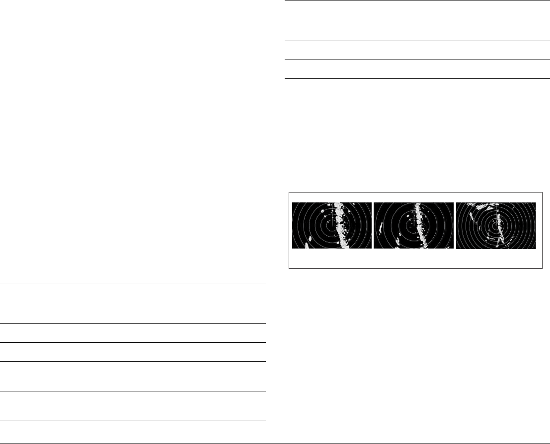
Rain or snow clutter
Radar detects rain and snow. Returns from storm areas and rain
squalls consist of countless small echoes which continually change
in size, intensity and position.
These returns sometimes appear as large hazy areas, depending
on the intensity of the rainfall or snow in the storm cell.
Mutual radar interference
This can occur when two or more radar-equipped vessels are oper-
ating within range of each other. The interference usually appears
as a spiral of small dots from the display centre, and is most
marked at long ranges.
D3968-4
D3967-4
G-Series Reference Manual 134
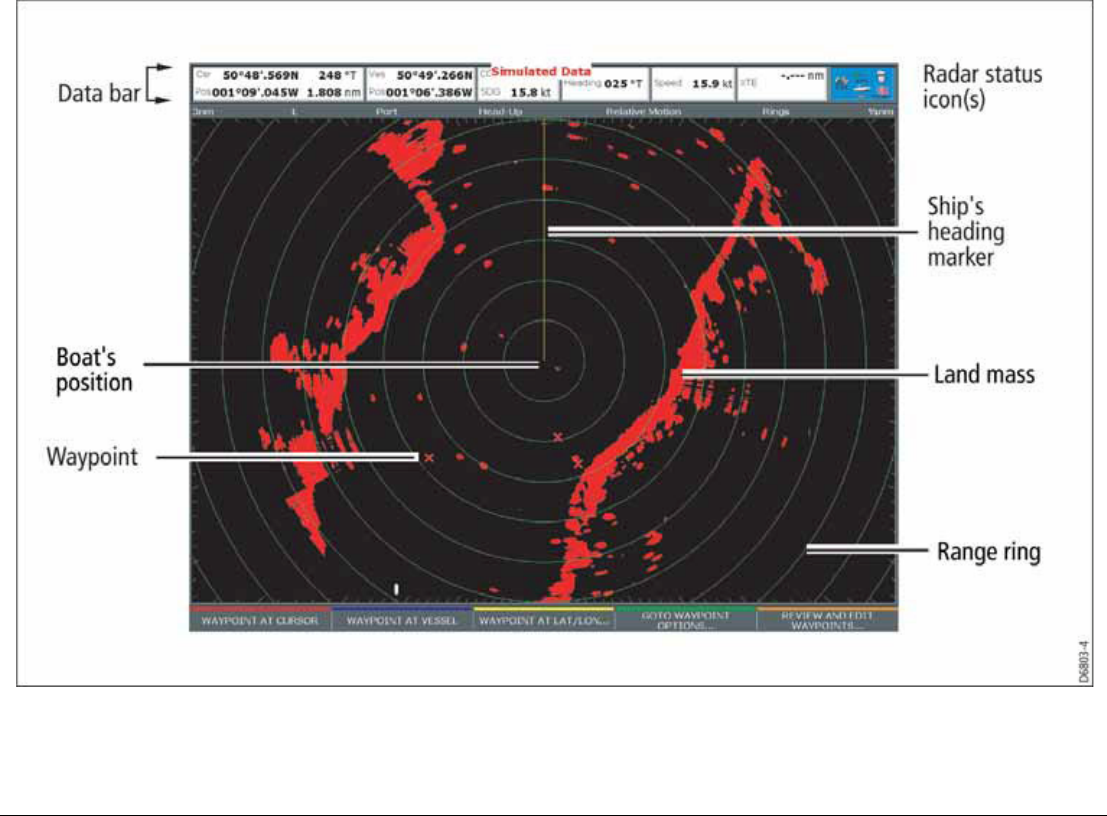
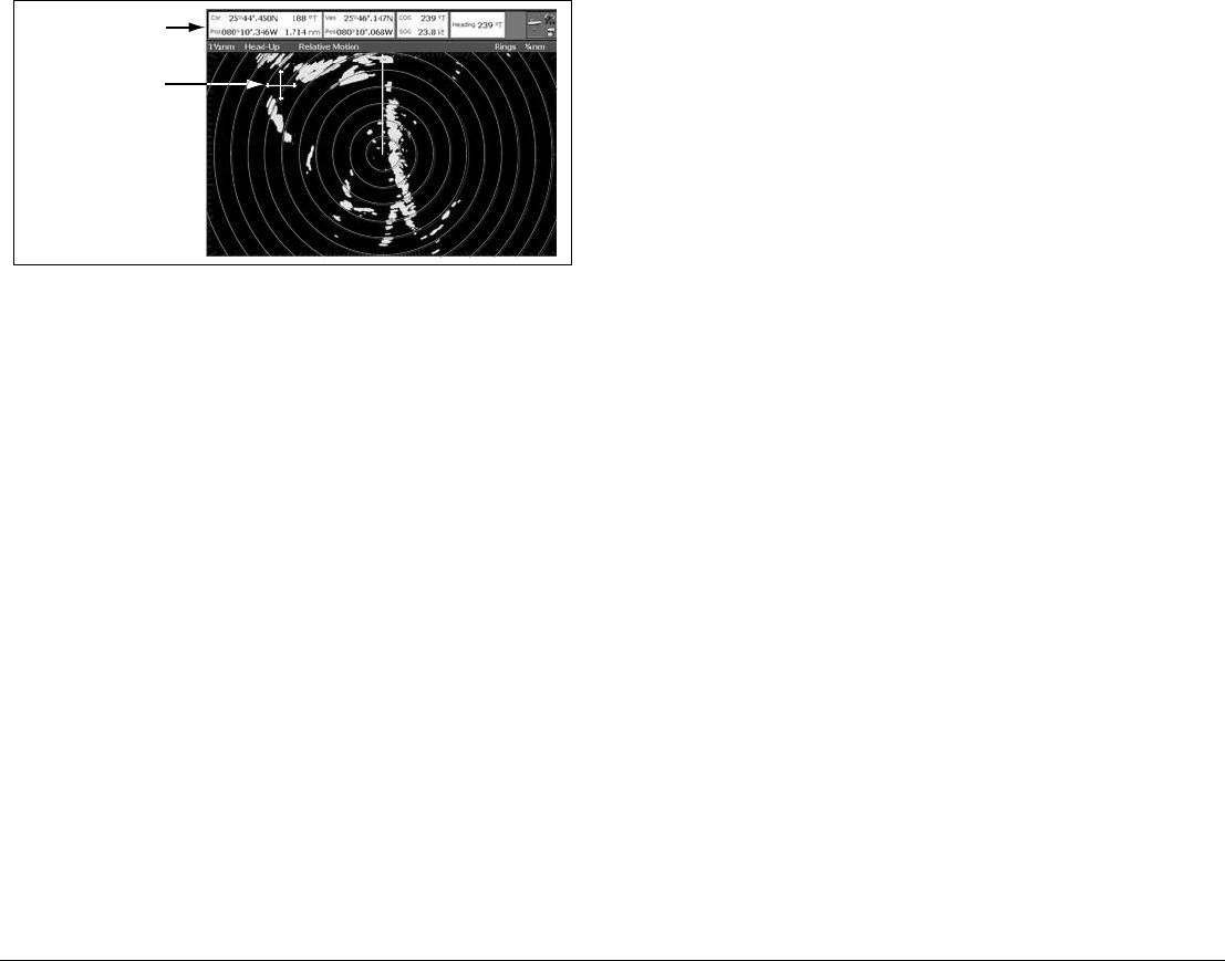
11.4 Radar window overview

135 Chapter 11: Radar
Your position
By default your boat is shown at the centre of the radar display and
your dead-ahead bearing is indicated by a vertical line known as
the Ship’s Heading Marker (SHM).
Operation modes
The radar gives excellent results in one of the four preconfigured
operation modes under the GAIN softkey. Select the mode that
best suits your circumstances: attempting to make manual adjust-
ments to the settings could degrade your image. (However, this
facility is available.)
See page 140 for more information.
Other vessels or objects
On-screen targets may be large, small, bright or faint, depending
on the size of the object, its orientation and surface type.
Remember that the strength of an object’s echo may not be propor-
tional to the physical size of the object. For example, a nearby
object might produce an echo of the same strength as a more dis-
tant, but larger, object.
With experience, the approximate size of different objects can be
determined by the relative size and brightness of the echoes.
Factors affecting echo strength
• The physical size of the reflecting object.
• The material from which the object is made. Metallic surfaces
reflect signals better than non-metallic.
• Vertical surfaces, like cliffs, reflect the radar signal better than
sloping surfaces, like sandbanks.
• High coastlines and mountainous coastal regions can be ob-
served at longer radar ranges. Therefore, the first sight of land
may be a mountain several miles inland from the coastline. Al-
though the coastline may be much nearer, it may not appear on
the radar until the vessel is closer to shore.
• Some targets, such as buoys and small boats, can be difficult to
discern, because they do not present a consistent reflecting
surface as they bob about in the waves. Consequently, these
echoes tend to behave erratically on the radar screen.
• Buoys and small boats often resemble each other, but boats
can often be distinguished by their motion.
• Trees and shrubbery do not reflect radar. Thus, they can dis-
guise the shape of nearby land.
11.5 Using waypoints with the radar
You can use waypoints in the radar application for navigation (just
like in the chart application), using the WPTS/MOB button.
You can also edit waypoints from within the radar application.
For full details on using waypoints, see Chapter 4:Using Waypoints
on page 35 and Chapter 5:The Chart Application on page 43.
G-Series Reference Manual 136
11.6 Radar display options
VRM/EBL TARGET
TRACKING
GAIN
Radar mode and orientation
Range rings on/off
AIS layer on/off
ENHANCE
ECHOES
PRESENTATION
Show/hide waypoints
Show waypoints menu
Show by symbol/group
On radar show/hide
Waypoint name on/off
Vessel offset 0, 1/3, 2/3
Motion mode true (TM)/relative (RM)
Orientation heading-up/north-up/course-up
Dual range long/short
D10570-1
137 Chapter 11: Radar
The presentation softkey on the radar toolbar gives you control
over:
• Waypoint behavior
• EBL
• Radar mode and display orientation
• Range rings
• AIS
These radar settings are locally applied, which means they affect
only the scanner and display on which you are working.
Orientation
Radar orientation refers to the relationship between the radar dis-
play and your direction of travel. There are three orientation modes:
• Head up
• North up
• Course up
These orientation modes are used in conjunction with motion
modes (see page 138) to control how your vessel’s progress is
shown on screen.
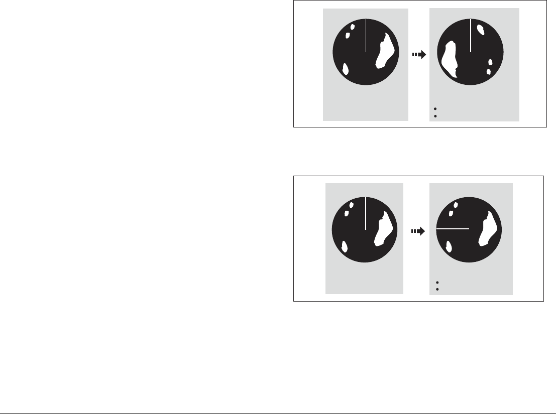
Heading-Up (H-UP)
This is the default mode for the radar application.
North-Up (N-UP)
If heading data becomes unavailable while in this mode, a warning
message will be shown, the status bar shows North-Up in brackets
and the radar uses 0° heading in relative motion. When heading
data becomes available once more, North-Up mode is reinstated.
It is not possible to select Head Up mode when the motion mode is
set to True.
Ship's Heading Market (SHM)
(indicating the boat's current
heading) is upwards
As your boat's heading changes:
SHM fixed upwards
Radar picture rotates accordingly
N
N
e.g:
D8398_1
N
e.g:
True north at top
N
D8399_1
As your boat's heading changes:
Radar picture fixed (north up)
SHM rotates accordingly
G-Series Reference Manual 138
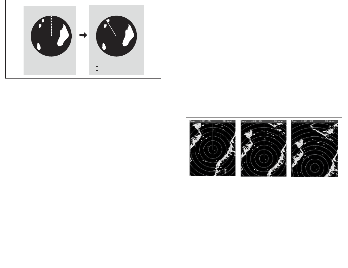
Course-Up (C-UP)
If you select a new course, the picture will reset to display the new
course upwards.
The reference used for Course-Up depends upon the information
available at a given time. The system prioritizes this information in
the following order:
1. Bearing from origin to destination (your intended course).
2. Locked heading from an Autopilot.
3. Bearing to waypoint.
4. Instantaneous heading.
If heading data becomes unavailable while in this mode a warning
message is displayed; the status bar puts Course-Up in brackets to
show it is suspended; and the radar uses 0° heading in relative
motion mode.
When heading data becomes available again, Course-Up mode is
reinstated.
To select an orientation mode
1. Press the PRESENTATION softkey.
2. Press RADAR MODE & ORIENTATION.
3. Choose your preferred setting under the ORIENTATION
softkey.
The selected orientation mode is displayed in the status bar.
Setting the motion mode
Motion modes control how your progress is represented on the dis-
play. The selected motion mode is displayed in the status bar. If no
position data is available, the status bar shows the motion mode in
brackets.
There are two motion modes:
• Relative motion
• True motion
The default setting is relative motion.
Relative motion (RM) with optional vessel offset
When the motion mode is set to Relative, the position of your boat
is fixed on the screen and all the targets move relative to the boat.
You can specify whether the boat is fixed in the centre of the win-
dow (0 offset) or offset by 1/3 or 2/3:
The default vessel-offset value is zero.
True Motion (TM)
When the motion mode is set to True, fixed radar targets maintain a
constant position and moving vessels (including your boat) travel in
true perspective to each other and to fixed landmasses on the
screen. As the boat’s position approaches the edge of the screen,
the radar picture is automatically reset to reveal the area ahead of
the boat.
Current course upwards
NN
D8400_1
As your boat's heading changes:
Radar picture fixed
SHM rotates accordingly
e.g:
D6842-2
0 offset 2/3 offset
1/3 offset

139 Chapter 11: Radar
If heading and position data become unavailable when true motion
is selected: a warning message is shown; the display reverts to rel-
ative motion; the status bar indicates that True Motion is selected
but suspended by showing it in parentheses (TM).
It is not possible to select True Motion when the orientation is set to
Head Up.
To set the motion mode
1. Press the PRESENTATION softkey.
2. Press RADAR MODE AND ORIENTATION.
3. Toggle between True and Relative Motion on the MOTION
MODE key.
To change the vessel offset
1. Press the PRESENTATION softkey.
2. Press RADAR MODE & ORIENTATION.
3. Toggle to your desired offset using the VESSEL OFFSET
softkey.
Changing the bearing mode for EBLs
The default bearing mode for EBLs is relative to your vessel’s
heading. If heading data is available, you can set the bearing mode
to be relative (REL) or magnetic/true (M/T).
When M/T is selected, the EBL bearings will be expressed as either
true or magnetic, depending on the equipment connected. The cur-
rent EBL bearing is given on the EBL label and on the ADJUST
EBL softkey label.
To change the EBL reference
1. Press the PRESENTATION softkey.
2. Toggle between M/T and REL on the EBL REFERENCE key.
Dual range
The G-Series system allows you to view either a short- or a long-
range image in separate radar windows. To allow this, dual range
must be enabled in the Radar Setup Menu (see Radar setup on
page 128).
To set the range
1. Press the PRESENTATION softkey.
2. Press RADAR MODE & ORIENTATION.
3. Toggle between LONG and SHORT on the DUAL RANGE
softkey.
The default setting is long, which provides a standard scanner
range. The short setting provides a maximum range of six or twelve
nautical miles.
Note: If chart-radar sync is turned on in the chart application, you
cannot enable dual range in the radar application. If dual
range is on, you cannot turn on chart-radar synchronization.
G-Series Reference Manual 140
11.7 Tuning the radar display: GAIN
Gain reduces the effect of false echoes and clutter. For best results, retain the default AUTO setting. You can, however, adjust gain settings
manually if required
.
VRM/EBL TARGET
TRACKING
GAIN
Threshold auto/man
Super HD controls
Adjust harbour mode
Rain on/off
Coastal mode
Sea auto/man Offshore mode
ENHANCE
ECHOES
PRESENTATION
Gain auto/man
Buoy mode
Power boost auto/manual
Antenna boost auto/manual
D10571-1

141 Chapter 11: Radar
Gain presets
There are four preset gain modes to give you the best picture in dif-
ferent circumstances.
Harbor is the default mode. This setting takes account of land clut-
ter so that smaller targets, like navigation buoys, are not lost.
Coastal accounts for the slightly higher levels of sea clutter you
might encounter out of harbor and adjusts the radar display
accordingly.
Offshore automatically adjusts for high levels of sea clutter.
Buoy is a special mode to enhance the detection of small objects
like mooring buoys. It is useful at ranges up to 3/4 nm.
Manually adjusting gain
The gain function makes the radar picture clearer by changing the
sensitivity of radar reception.
•For long ranges select a sensitivity level that gives a slight
speckle in the background. Setting the gain too low can cause
weak or small targets to disappear, however.
•For shorter ranges reduce the gain slightly to reduce speckle
and improve target definition.
Note: If you control gain manually, check it each time you change
the range scale.
To manually adjust gain settings
1. Press the GAIN softkey.
2. Press the ADJUST softkey for the preset mode you are in.
3. Select manual on the GAIN softkey.
The changes you make are applied to both the active window and
any other radar windows displaying this preset. Gain setting
changes are kept at system power-off.
Rain clutter
Radar detects echoes from rain or snow. The strength of these ech-
oes depends upon the altitude, range, density and size of the snow
flakes or rain droplets and appear on screen as countless small
echoes continuously changing size, intensity and position.
Turning the RAIN clutter function on suppresses the bulk effect of
rain returns from around your boat, so that recognizing other
objects is easier.
Sea clutter
Radar echoes from waves around your boat can clutter the centre
of the radar picture, making it difficult to detect real targets (see
page 131).
Adjusting the sea mode will reduce this clutter for up to 5 nautical
miles (depending on wave and sea conditions) from your boat. This
reduces sea echoes to intermittent small dots, while small targets
remain visible and persistent. Gain levels further from your boat
remain unchanged.
Super HD adjustments
You can generally use the default AUTO settings for best results,
but two manual controls allow you to explore Super HD’s
capabilities.
Antenna boost
This scales the effective antenna size. At zero, the effective
antenna size matches its actual size. At 95, the effective antenna
size is doubled.
Increasing effective antenna size has the effect of separating tar-
gets that appear merged at lower settings.

G-Series Reference Manual 142
In some circumstances, a larger effective scanner can be a draw-
back. In particular, if you are in a harbor or close to land, you may
see more detail than is useful.
For that reason, the AUTO settings for Harbor and Coastal modes
provide lower scale factors of about 30% and 60%.
Power boost
This adjusts effective transmit power. At zero, the radar operates at
its standard power (4kW or 12kW). At 90, the effective power is
increased by a factor of at least two.
Increasing power has the effect of making targets more distinct
from noise. For maximum benefit, reduce gain to prevent saturation
of strong targets.
The default power boost setting for all AUTO modes is 90.
143 Chapter 11: Radar
11.8 Tuning the radar display: ENHANCE ECHOES
The ENHANCE ECHOES softkey gives you access to further features for tuning the radar display.
Interference rejection
Interference rejection automatically reduces mutual radar interfer-
ence when two radar-equipped vessels are operating within range
of each other. It is switched on by default.
You can adjust the strength of interference rejection in the Radar
Setup Menu.
Turning interference rejection off altogether allows you to detect the
presence of other radars in the vicinity.
To turn interference rejection off
1. Press the ENHANCE ECHOES softkey.
2. Toggle the setting to OFF on the INT REJECT softkey.
VRM/EBL TARGET
TRACKING
GAIN
Expansion on/off
Wakes on/off
Scan to scan on/off
ENHANCE
ECHOES
PRESENTATION
Interference rejection on/off
D10572-1

G-Series Reference Manual 144
Expansion
The expansion function allows you to either override the pulse
length or to give larger returns so targets are easier to see.
To override the pulse length
1. Open the Radar Setup Menu. You can either use the MENU
button, or press and hold the EXPANSION softkey.
2. Set the magnification level for target expansion to HIGH.
To give larger returns
1. Open the Radar Setup Menu.
2. Set the magnification level for target expansion to LOW.
Note: Selecting this option may compromise target resolution.
Wakes
When the wakes function is switched on, you can see the direction
and speed of moving targets relative to your boat. Targets are dis-
played in yellow, turning to paler shades of blue as the signal
diminishes.
The wakes option is a local setting which applies only to the display
on which you are working. You can choose to display wakes for a
period of 10 seconds, 30 seconds, 1 minute, 5 minutes or 10
minutes.
To switch wakes display on
1. Press the ENHANCE ECHOES softkey.
2. Toggle wakes to ON using the WAKES softkey.
3. Select your preferred wakes setting.
4. Press OK.
To switch wakes display off
1. Press the ENHANCE ECHOES softkey.
2. Press the WAKES softkey.
3. Press the CLEAR WAKES softkey.
Scan to scan
When scan to scan is switched on, stationary objects appear stron-
ger with each sweep of the radar. If the object moves, it appears
relatively weakly on screen.
This can be used to reduce the effects of rain and sea clutter.
To switch scan to scan on or off
1. Press the ENHANCE ECHOES softkey.
2. Toggle to ON or OFF using the SCAN TO SCAN softkey.
3. Press OK.
11.9 Radar range
You can zoom in or out to view the radar display at different scales.
The scale is measured from the centre to the top of the window and
is displayed in the left-hand corner of the status bar.
•Short-range scales show nearby objects in greater detail, and
are most suitable as you approach coastlines, harbors, or other
vessels. The shortest range available is 1/8 nautical miles.
•Long-range scales provide the best overview of the vessel’s
relationship to landmasses, weather fronts and large ships with-
in or beyond your field of vision. The longest range available is
72 nautical miles, depending upon the scanner fitted.
To change the radar range
1. Zoom to your required scale using the RANGE button on the
keyboard.
Synchronizing radar range and chart scale
The chart application includes an option to synchronize the radar
range with the chart scale.
When synchronization is switched on:
• The radar range in all radar windows changes to match the
chart scale.
145 Chapter 11: Radar
• ‘Sync’ is displayed in the top left-hand corner of the chart
window.
• If you change the radar range, all synchronized chart views
change scale to match.
• If you change the scale of a synchronized chart window, all ra-
dar windows update to match.
To synchronize radar range and chart scale
1. Make a chart window active.
2. Press the PRESENTATION softkey.
3. Press CHART MODE AND ORIENTATION.
4. Toggle to RDR on the CHART SYNC softkey.
Note: Radar range synchronization is not available when the chart
motion mode is set to autorange, nor when the selected
scanner is set to dual range.
11.10 Measuring distance, range and
bearing
You can measure distance, range and bearing in the radar applica-
tion. Options for doing so are detailed in the table below.
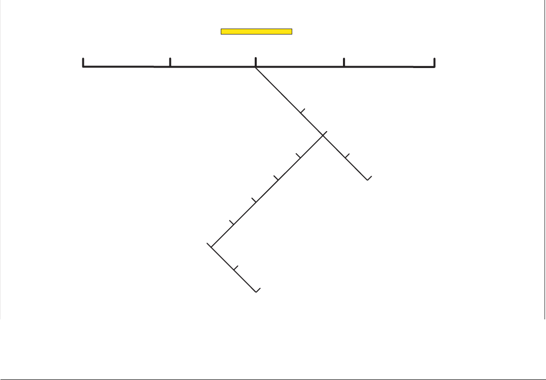
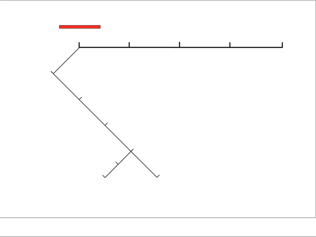
Range rings
Range rings help you gauge the approximate distance between
points at-a-glance. Range rings are centred on your position and
displayed on the screen at pre-set intervals.
The number and spacing of range rings changes to suit the scale
you have set.
To show or hide range rings
1. Press the PRESENTATION softkey.
2. Toggle to ON or OFF using the RANGE RINGS softkey.
Bearing and range
The radar display shows you bearing and range data to any object
you highlight.
To find the bearing and range to an object
1. Move the cursor to the object’s position.
2. Read off the bearing and range in the databar.
Functions
Distances
between
points
Range from
your boat Bearings
Range Rings Yes (approx.) Yes (approx.) -
Cursor - Yes Yes
Variable Range
Markers (VRMs)
- Yes -
Electronic Bearing
Lines (EBLs)
- - Yes
Floating VRMs Yes - -
Floating EBLs - - Yes
Functions
Distances
between
points
Range from
your boat Bearings
Range - 1/4 nm
Range rings - 1/8 nm apart
Range - 3/4 nm
Range rings - 1/4 nm apart
Range - 11/2 nm
Range rings - 1/4 nm apart
D8407_1
e.g.
G-Series Reference Manual 146
Bearing and range from
your vessel to cursor
D8402_1
Cursor
147 Chapter 11: Radar
The Variable Range Marker (VRM) and Electronic Bearing Line (EBL)
The VRM/EBL softkey opens the toolbars shown below:
VRM/EBL TARGET
TRACKING
GAIN
Adjust VRM
Adjust EBL
Adjust Float
Center
Floating EBL
Setup VRM/EBL 2
VRM/EBL on/off
ENHANCE
ECHOES
PRESENTATION
D10573-1
G-Series Reference Manual 148
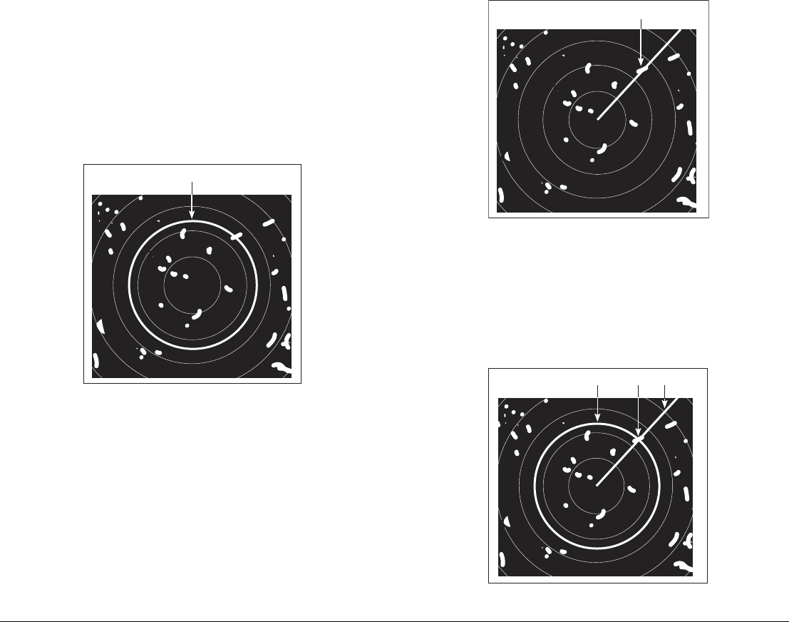
Variable Range Marker
A Variable Range Marker (VRM) is a circle of variable radius cen-
tred on your vessel’s position.
You can use the VRM to measure the distance from your vessel to
a selected object by adjusting the radius of the marker so that it
intersects the object’s position.
The range is displayed on the ADJUST VRM softkey label when
you highlight the VRM.
Electronic Bearing Marker
An Electronic Bearing Line (EBL) is an on-screen marker drawn
from your position to the edge of the window.
When this line is rotated to align with a target, the bearing relative
to your current heading is measured and displayed on the ADJUST
EBL softkey label.
The data is also displayed if you select the EBL with the cursor.
To change the EBL reference from relative to magnetic or true, see
page 139.
Combined range and bearing
You can combine a VRM and an EBL to measure range and bear-
ing simultaneously:
D8408_1
VRM
D8425_1
EBL
D8403_1
EBL
VRM Target

149 Chapter 11: Radar
Tracking a target with a VRM or EBL
You can tell which direction an object is travelling in by tracking its
movement in relation to the EBL. If it continues travelling towards
the EBL, it could be on a collision course with your boat.
To create a VRM or an EBL
1. Press the VRM/EBL softkey.
2. Toggle to ON with the VRM/EBL softkey.
3. To adjust settings, press either the ADJUST VRM or ADJUST
EBL softkey and make changes with the rotary controller.
To place a second VRM or EBL
1. Press the SET UP VRM/EBL 2 softkey.
2. Proceed as with VRM/EBL 1.
Floating VRM and EBL
The VRM/EBL float function allows you to measure range and
bearing between any two points on the radar screen (rather than
from your vessel’s position).
First you move the VRM/EBL centre to the position you want to
measure from. Then you change the radius of the VRM to measure
distance, or change the angle of the EBL to take a bearing.
To use floating VRM
1. Create a standard VRM.
2. Highlight the VRM or press the VRM/EBL softkey.
3. Press the FLOATING VRM softkey.
4. Press the ADJUST FLOAT softkey.
5. Move the cursor to the point to measure from.
6. Press OK.
7. Move the cursor to the point to measure to.
8. The range between the two points is shown on the ADJUST
VRM softkey label.
To use floating EBL
1. Create a standard EBL.
2. Highlight the EBL or press the VRM/EBL softkey.
3. Press the ADJUST EBL softkey.
4. Adjust the direction and start point of the EBL using the
trackpad and rotary controller.
5. The bearing is shown on the ADJUST EBL softkey label.
To use a second floating VRM or EBL
1. Press SET UP VRM/EBL 2.
2. Toggle VRM/EBL 2 to ON.
3. Repeat the steps for using a floating VRM (steps 1-8).
To unfloat a VRM or EBL
1. Press the VRM/EBL softkey.
2. Press the FLOATING EBL softkey (under SET UP VRM/EBL 2
if you are using a second floating VRM or EBL).
3. Select CENTER.
4. Press OK.
G-Series Reference Manual 150
11.11 Using radar to track objects
The TARGET TRACKING softkey opens the toolbars shown below:
VRM/EBL TARGET
TRACKING
GAIN
Acquire target
Monitor in zones
MARPA & AIS options
Zone 1 on/off
Setup zone 1
Zone 2 on/off
Setup zone 2
Options window
MARPA list window
Cancel all targets
Cancel target
ENHANCE
ECHOES
PRESENTATION
MARPA list
D10573-1
151 Chapter 11: Radar
Target tracking functions are used to help avoid collisions.
•Guard zones sound an alarm when an object comes within a
specified range.
•MARPA displays information about tracked objects.
•AIS displays the identity and voyage information of other AIS-
enabled vessels.
To track a target
1. Press the TARGET TRACKING softkey.
2. Highlight the object you wish to track.
3. Press the ACQUIRE TARGET softkey.
The ‘target being acquired’ icon is displayed, followed by the appro-
priate MARPA status icon.
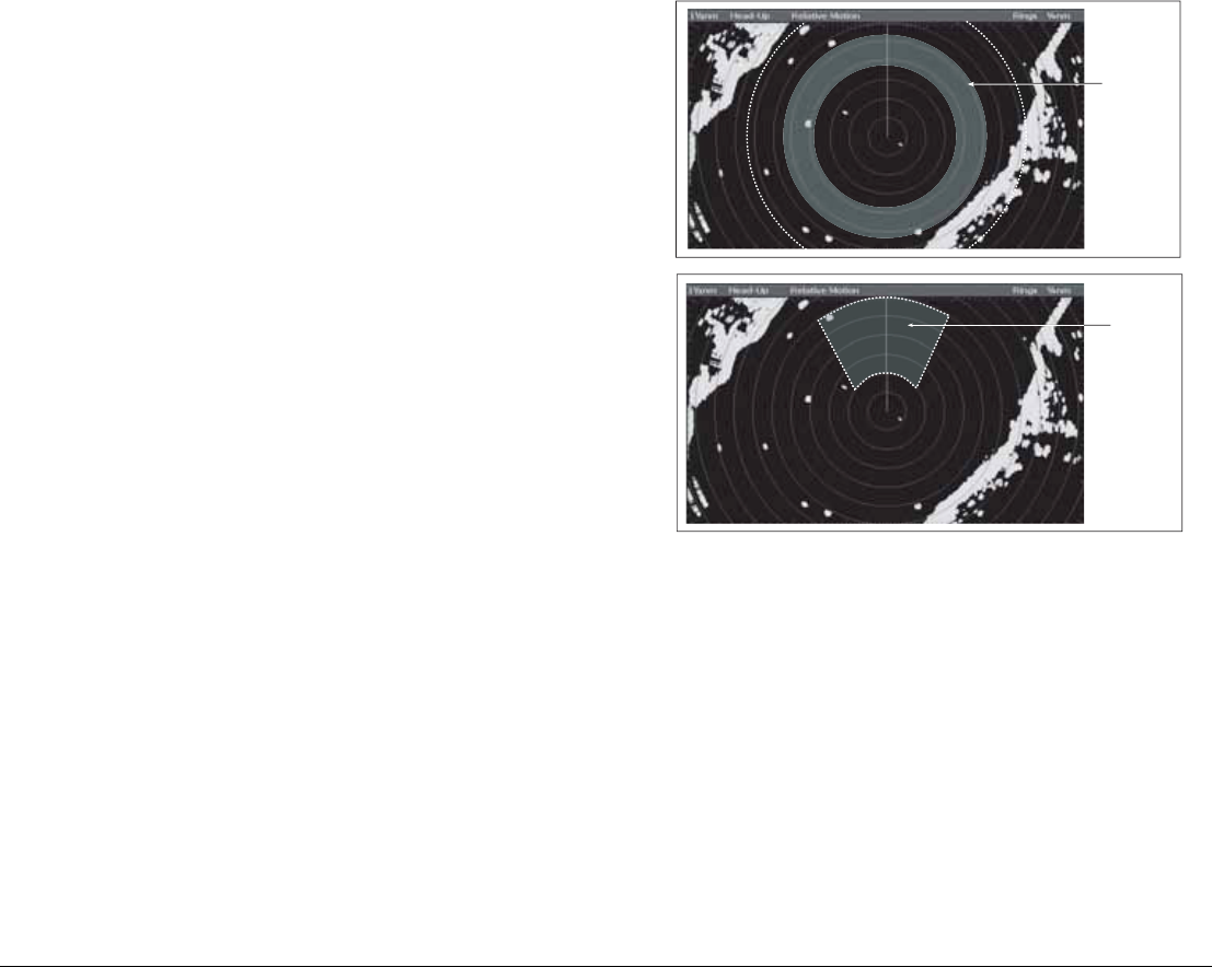
Guard zones
A guard zone is a ‘protected’ area around your vessel: as soon as
an object (like another vessel) enters the zone, it triggers an alarm
on your Nav Station. Guard zones are managed from the Monitor in
Zones toolbar.
Guard zones can be either circular- or sector-guards, and you can
define up to two of them on your system. You can adjust the sensitivity of guard zones on the Alarms Setup
Menu. For more information, see Alarm Setup Menu on page 194.
Guard zones only operate when the whole zone is displayed on the
screen. To avoid inappropriate alarms, they become active ten sec-
onds after being placed or edited.
To place a guard zone
1. Press the TARGET TRACKING softkey.
2. Press the MONITOR IN ZONES softkey.
3. Toggle ZONE 1 or ZONE 2 to ON, as appropriate.
4. Press the corresponding SET UP ZONE softkey.
5. Choose your zone shape.
6. Set the limits of the guard zone using the rotary controller.
7. Press OK.
6nm Head
-
Up
D6832-2
Circular
Guard Zone
6nm Head-Up Relative Motion Rings 1nm
D6815_3
Sector
Guard Zone

G-Series Reference Manual 152
MARPA
The Mini Automatic Radar Plotting Aid (MARPA) provides target-
tracking and risk-analysis features. MARPA obtains detailed infor-
mation for up to ten automatically tracked objects and provides
continuous, accurate and rapid situation analysis.
To use MARPA, you need a fast heading sensor.
Setting up MARPA
You can customize the following parameters from the MARPA
Options menu:
To open the MARPA Options menu
1. Press the TARGET TRACKING softkey.
2. Press the MARPA & AIS OPTIONS softkey.
3. Change MARPA options as required.
Safety notices
MARPA can improve collision avoidance when used wisely. It
is the User’s responsibility to exercise common prudence and
navigational judgements.
There are certain conditions under which acquiring a target may
become difficult. Some of those conditions are:
• The target echo is weak.
• The target is very close to land, buoys or other large targets.
• The target or your own ship is making rapid manoeuvres.
• Choppy sea state conditions exist and the target is buried in ex-
cessive sea clutter or in deep swells.
• Choppy sea state conditions exist yielding poor stability.
• Inadequate heading data exists.
Symptoms of such conditions are that acquisition is difficult and the
MARPA vectors are unstable; the symbol wanders away from the
target, locks on to the wrong target or changes to a lost symbol
target.
If any of these conditions are present, acquisition and tracking may
need to be re-initiated or, in some cases be impossible to maintain.
Improving the quality of the heading data will reduce the effect of
the other conditions.
To acquire a target
MARPA automatically tracks acquired targets, calculates target
bearing and range, speed and course, Closest Point of Approach
(CPA), and Time to Closest Point of Approach (TCPA).
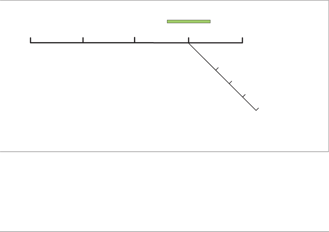
Parameter Options
Vector Length
The time period specified for drawing
length of vectors.
0.5min, 1 min, 3 min, 6min,
12min, 30 min, 60 min
Target History
Plots a target’s previous position at the
specified intervals. The four most recent
position points are displayed. If True
target vectors are selected, the four most
recent vessel position points are also
displayed.
OFF, 0.5 min, 1 min, 3 min, 6 min
Own vessel safe zone
The safe zone is a ring, centred on your
boat, within which a target is considered
dangerous if it will enter this zone within
the time to safe zone period.
0.1 nm, 0.2nm, 0.5nm, 1.0 nm,
2.0nm
Time to safe zone
If a target enters your safe zone within this
time period, it is considered dangerous.
3 mins, 6 mins, 12 mins, 24 mins
Safe zone ring
Controls whether the safe zone ring is
displayed or hidden on screen
Visible
Hidden
153 Chapter 11: Radar
Each target tracked can be displayed with a CPA graphic which
shows the target vessel, course and speed (as a vector) and indi-
cates the CPA. The calculated target data can also be shown on
your screen. Each target is continually assessed and an audible
alarm is sounded if a target becomes dangerous, or is lost.
Effective MARPA operation is dependant on accurate own-ship’s
heading and speed. Speed Over Ground (SOG) and Course Over
Ground (COG) information are required to show true target course
and speed. The better the quality of the heading and speed data,
the better MARPA will perform. MARPA will function without SOG
and COG in relative mode. For the best heading data a Raymarine
SMART heading sensor or a gyro-stabilized autopilot is required.
Risk assessment
Each target is monitored to see if it will be within a certain distance
from your boat within a certain time. If so, the target is designated
as dangerous and an audible warning is sounded along with an on-
screen warning being shown. The target symbol changes to the
dangerous target symbol and flashes to indicate that it is a danger-
ous target. Pressing the appropriate soft key will silence the alarm
and remove the warning.
If a target is lost, either because the MARPA software has lost con-
tact with it, or because it has moved out of range, an audible alarm
is sounded and an on-screen warning appears. The on-screen
symbol will change to the target lost symbol. Pressing the appropri-
ate soft key will silence the alarm and remove the on-screen
warning and the target lost symbol.
MARPA range
MARPA target acquisition is only available at radar range scales of
up to 12nm, although tracking continues at all ranges.
If you change to a smaller range scale, targets may be beyond the
range of your scanner and will be lost. In such cases, an on-screen
warning will indicate that the target is off-screen.
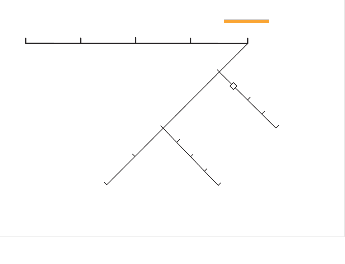
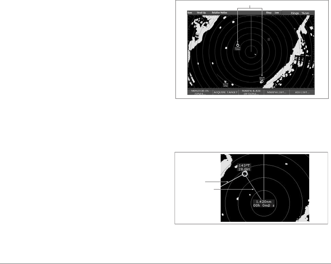
Closest point of approach
Closest point-of-approach (CPA) graphics show vectors for your
vessel and a selected target. (A vector is a line showing a predicted
course.) Vector length varies with speed (settings can be changed
in the MARPA Setup Menu).
To show or hide closest point-of-approach
1. Highlight the object with the cursor.
MARPA targets
D6810_4
D9008_1
Vector
CPA graphic
3 9
G-Series Reference Manual 154
2. Toggle to the required CPA setting using the CPA GRAPHIC
softkey.
How motion modes affect CPA
In true motion mode, the vectors of your vessel and the target are
shown extended to their intersection point. The CPA is shown as a
line that is placed on your boat’s vector at the point of the CPA. The
length and direction of the line indicates the distance and bearing of
the target at CPA. The text indicates CPA and TCPA. The text next
to the target symbol indicates its true course and speed.
In relative motion mode, no vector extension of your boat is
shown. The CPA line emerges from your own boat, with the target
vector extension being shown as relative, not true. The text next to
the target indicates its course and speed.
Press SHOW DETAILS to display the calculated relative course
and speed.
Displaying MARPA data
All MARPA data is held in a list containing:
• MARPA ID
• Bearing
• Range
• True Course
• True Speed
• CPA
• TCPA
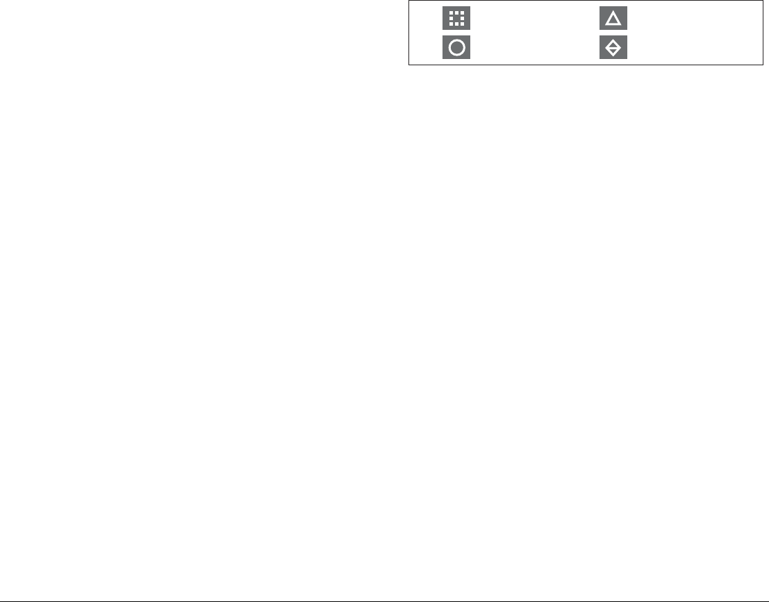
Target display
The position of MARPA objects is marked with an icon, which also
indicates its MARPA status.
To view the MARPA list
1. Press the TARGET TRACKING softkey.
2. Press the MARPA LIST softkey.
To cancel MARPA directly
1. Highlight a tracked MARPA object.
2. Press either the CANCEL TARGET or CANCEL ALL
TARGETS softkey, as appropriate.
To cancel MARPA from the MARPA list
1. Open the MARPA list.
2. Select a target and press CANCEL TARGET or CANCEL ALL
TARGETS, as required.
Displaying vessel identity (AIS)
If you have an AIS receiver fitted to your system, you can use it to:
• Show the position and display vessel data for other AIS-
equipped vessels within a specified range of your boat.
• Display voyage data (position, course, speed and rate of turn)
of AIS-equipped vessels.
• Display basic or detailed information for each target vessel in-
cluding safety critical target data.
• Set up a safe zone around your boat.
• View alarm and safety related messages.
This information is displayed in the form of an overlay or as a dialog
box on your radar screen. For more information about AIS, see
Chapter 12:Automatic Identification System on page 157.
D7542_2
Dangerous target
Safe target
Target being acquired
Lost target

155 Chapter 11: Radar
To overlay AIS on a radar window
1. Press the PRESENTATION softkey.
2. Toggle the AIS LAYER to ON.

G-Series Reference Manual 156

12
Chapter 12: Automatic Identification System
The Automatic Identification System (AIS) provides safety features when you are at sea.
On the G-Series system, AIS is overlaid on a chart or radar widow. It provides:
• Heading, speed and rate of turn data for nearby AIS-equipped vessels.
• A ‘safe zone’ around your boat.
• Alarms and safety messages.
Chapter contents
• 12.1 Background on page 158
• 12.2 System requirements on page 158
• 12.3 System settings on page 158
• 12.4 AIS setup on page 158
• 12.5 Using AIS on page 159
• 12.6 The AIS data display on page 159
• 12.7 Displaying AIS vectors on page 160
• 12.8 Displaying safety-critical AIS data on page 160
• 12.9 Safe zones on page 161
• 12.10 MARPA and AIS options on page 162
• 12.11 AIS alarms on page 163
• 12.12 Simulator mode on page 163

G-Series Reference Manual 158
12.1 Background
AIS broadcasts information between vessels and shore-based sta-
tions on VHF frequencies in the maritime band. This information is
used to provide fast, automatic and accurate collision-avoidance
data. AIS augments the radar application. It can operate in radar
blind spots and can detect smaller (AIS-equipped) vessels than
radar can.
AIS does not replace radar, because it is unable to detect land or
navigation beacons.
Classes of AIS data
AIS data is defined as Class A or Class B. The sending and receiv-
ing of Class A data is compulsory for larger vessels. You will
therefore be able to view all larger vessels on your AIS display.
Not all AIS receivers will decode all information and not all of the
Class A vessels input all of the required AIS data. For example,
some inexpensive AIS Class B receivers do not decode and output
the ship’s name, IMO number and vessel data.
Class B data is applicable to smaller vessels and is not compulsory.
Do not assume that your AIS will display data for all smaller vessels
in your area.
The following information can be transmitted by a Class A AIS
system:
•Static data: ship name, type, MMSI number, call sign, IMO
number, length, beam and GPS antenna location.
•Voyage data: draft, cargo, destination, ETA, other relevant
information.
•Dynamic data: time, position, COG, SOG, gyro heading, rate of
turn, navigational status.
•Dynamic reports: speed and status.
•Messages: alarm and safety.
12.2 System requirements
To use AIS, you need:
•AIS unit: either a receive-only or full transceiver device.
•VHF antenna
12.3 System settings
For the NMEA port that communicates with the AIS transceiver
unit, specify a baud rate of 38,400 (see page 188).
12.4 AIS setup
The AIS Layer Setup Menu allows you to:
• Select target types displayed (ALL or DANGEROUS).
• Switch AIS safety messages on or off.
• View the list of active AIS alarms.
To display the AIS Layer Setup Menu
1. Ensure the AIS LAYER is set to ON (see Using AIS, below).
2. Press the MENU button.
3. Select AIS Layer Setup.
WARNING
Product installation
Smaller vessels do not have to be fitted with AIS, and
although it is mandatory for larger commercial vessels to
use AIS, do not assume that they all do. Always exercise
due prudence and judgement.
AIS complements radar, it is not a radar substitute.
159 Chapter 12: Automatic Identification System
12.5 Using AIS
AIS is a selectable layer of the chart or radar application.
To switch AIS layer on
1. With either a chart or radar window active, press the PRESEN-
TATION softkey.
2. If you are in a radar window, toggle AIS on or off using the AIS
LAYER softkey.
If you are in a chart window, press the CHART LAYERS
softkey to open the toolbar containing SYMBOLOGY, then
select AIS.
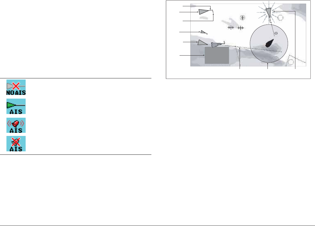
AIS status icons
Status icons are displayed in the data bar.
12.6 The AIS data display
Suitably AIS-enabled vessels (or AIS ‘targets’) appear as triangular
symbols. Up to 100 targets can be displayed.
Vectors can be displayed for each target. These vectors indicate
the direction of travel and rate of turn of the vessel and the distance
it will travel over a specified period of time (COG/SOG vector). Tar-
gets displayed with their vectors are referred to as ‘active targets’
and are scaled according to the size of the vessel.
You can choose to display all targets or just the dangerous ones
(see page 158).
oo
No recent AIS messages.
There are recent AIS messages.
AIS unit on with active alarms.
AIS unit switched on and operating but dangerous and
lost alarm disabled.
D9541-1
D9056_1
097°T
11.6kt
1.237nm
00h04m33s
Safety
critical data
Heading
Large
vessel
Direction
of turn
Small
vessel
Sleeping
target
Dangerous
target (flashes)
Safe zone (defined by
distance or time)
COG/SOG
vector
G-Series Reference Manual 160
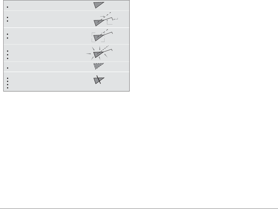
AIS Target symbols
AIS target symbols are summarized below.
Viewing AIS information
You can display information relating to individual AIS targets.
To see AIS data for a selected target
1. Highlight the AIS target with the cursor.
2. Select the appropriate data from the toolbar.
The AIS toolbar
Softkeys on the AIS toolbar give you access to:
• AIS vectors
• AIS safety critical data
• AIS List
• Full AIS data
12.7 Displaying AIS vectors
The AIS vector feature gives you the following data for selected
targets:
• A COG/SOG vector indicating the predicted distance that a tar-
get will travel within a given period of time.
• Graphical representation of heading and direction of turn.
To switch AIS vectors on or off
1. Highlight the AIS target for which you want to display vectors.
2. Toggle to your desired setting on the AIS VECTOR softkey.
12.8 Displaying safety-critical AIS data
Safety-critical target data such as COG, SOG, CPA and TCPA can
be displayed in the tag alongside each target. You can switch this
data on or off or set it to display it automatically when the cursor is
over the target.
To view AIS data
1. Highlight an AIS target.
2. Toggle to your preferred setting on the AIS DATA softkey:
AUTO (default): safety-critical data shown when the cursor is
over the target.
ON: safety-critical data shown constantly.
OFF: safety-critical data never shown.
Uncertain target
Calculated CPA/TCPA value uncertain.
Sleeping target
Target not activated, dangerous or lost.
Activated target
Target activated i.e. AIS vector displayed.
Vector line (optional) shows predicted distance travelled within
given time.
Dangerous target
Targets within specified distance (CPA) or time (TCPA).
Dangerous target alarm sounds if en-abled.
Target flashes.
Lost target
When signal of dangerous target not received for 20 seconds.
Target in latest predicted position.
Alarms sounds if enabled.
Target flashes.
Selected target
Target selected with cursor.
Can activate the target and view detailed data.
COG/SOG
vector
Heading
Direction
of turn
AIS
D8523-1
161 Chapter 12: Automatic Identification System
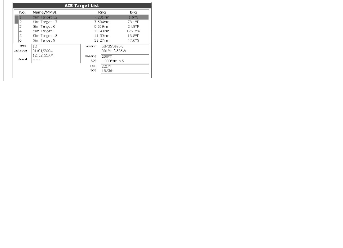
AIS list
The AIS list provides collision-avoidance data for the highlighted
target:
To display the AIS List
1. Make a chart window active, with AIS Layer turned on.
1. Press the AIS OPTION softkey.
2. Press the TARGET TRACKING softkey.
3. Select AIS LIST.
Full AIS data
Full AIS data for an individual target includes static, dynamic and
voyage related data.
To view full AIS data for a target
1. Highlight the target with the cursor.
2. Press the VIEW FULL AIS DATA softkey.
or
1. Select the target on the AIS list.
2. Press the VIEW FULL AIS DATA softkey.
12.9 Safe zones
A safe zone is a circular area about your vessel. If another vessel
enters this area, the G-Series system considers it dangerous. The
perimeter of the zone is displayed on the radar and chart window
as a red ring.
The AIS safe zone uses the same criteria as MARPA and will deem
a target dangerous if it comes within a specified distance of your
vessel (closest point of approach, or CPA) within a specified time
(time to closest point of approach, or TCPA). The CPA and TCPA
are calculated using COG/SOG and position from the AIS target.
When the system recognizes a dangerous AIS target:
• The target symbol changes to red and flashes.
• An warning is displayed.
• An alarm sounds (if AIS alarm is enabled).
Safe zone alarm
You can disable the dangerous target alarm. Doing so will prevent
the visual warning from displaying and the audible alarm from
sounding, but dangerous targets are still displayed in red.
The AIS status icon shows the current status of AIS alarms.
The dangerous target alarm operates irrespective of the status of
the AIS target display or the status (VISIBLE/HIDDEN) of the safe
zone ring.
To set up an AIS safe zone
1. Press the TARGET TRACKING softkey.
2. Press the MARPA and AIS OPTIONS softkeys.
3. Select Own Vessel Safe Zone and set the radius of your safe
zone.
D9092_1

G-Series Reference Manual 162
Time to safe zone
The time to safe zone function calculates how long it will take other
AIS-equipped vessels to reach your safe zone, based on their AIS
data. You can set your system to alert you when such vessels
reach a designated ‘time to safe zone’.
To set the time to safe zone
1. Press the TARGET TRACKING softkey.
2. Press the MARPA and AIS OPTIONS softkey.
3. Select Time to Safe Zone in the MARPA & AIS OPTIONS
menu.
12.10 MARPA and AIS options
Safety messages
When AIS Safety Messages is on (controlled from the AIS Layer
Setup Menu), incoming safety messages from vessels, shore sta-
tions and mobile stations are displayed in a pop-up box. The
message will include latitude and longitude if it is available.
Whenever you receive a safety message, the system gives you
options to:
• Remove the message (ACKNOWLEDGE).
• Place a waypoint to mark the sending vessel’s position.
Parameter Options
Vector Length
The time period specified for drawing length of
vectors.
0.5min, 1 min, 3 min,
6min, 12min, 30 min, 60
min
Target History
Plots a MARPA target’s previous position at speci-
fied intervals. The four most recent position points
are displayed. If True target vectors are selected,
the four most recent vessel position points are also
displayed.
OFF, 0.5 min, 1 min, 3
min, 6 min
Own vessel safe zone
The safe zone is a ring, centred on your boat, within
which a target is considered dangerous if it comes
within a specified distance (CPA).
0.1 nm, 0.2nm, 0.5nm,
1.0 nm, 2.0nm
Time to safe zone
If a target enters your safe zone within this time
period, it is considered dangerous.
3 mins, 6 mins, 12 mins,
24 mins
Safe zone ring
Controls whether the safe zone ring is displayed or
hidden on screen
Visible
Hidden
163 Chapter 12: Automatic Identification System
• GOTO the sending vessel’s position.
Note: When the simulator is operating you will not be able to
receive any safety messages.
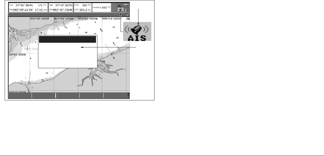
12.11 AIS alarms
In addition to the dangerous target alarm, the system generates an
alarm when a dangerous target becomes lost (this happens if the
AIS signal from a tracked vessel is not received for more than 20
seconds).
When the connected AIS unit generates an alarm, the G-Series
system indicates the alarm status in the data bar and displays a
warning message:
Active alarm list
The active alarm list shows the status of each local alarm. This list
can either be accessed via the AIS Layer Setup Menu (see
page 158) or from the Alarms Setup Menu (see page 194).
To acknowledge an AIS alarm
1. Press either the REMOVE MESSAGE or VIEW AIS ALARM
LIST softkey.
2. Acknowledge the message at your AIS unit.
Note: Alarms remain active until they are acknowledged on the
AIS unit. Removing the message or adding it to the Alarm
list on your G-Series system does not cancel the alarm.
12.12 Simulator mode
We recommend that you use the simulator to familiarize yourself
with the AIS function.
When the system simulator is switched on (see page 29), it dis-
plays 20 AIS targets within a 25nm range. These targets are
displayed using the appropriate AIS targets status symbol (see
page 160) and move around the screen as if they were real targets.
Note: Incoming safety messages cannot be displayed while the
simulator is switched on.
REMOVE
MESSAGE
VIEW AIS
ALARM LIST...
4nm North-Up (Relative Motion) Local
AIS message
AIS Local Alarm
This alarm must be acknowledged on your
AIS Receiver.
To remove this message press REMOVE
MESSAGE.
"AIS message"
D8968_1
AIS Alarm
active icon

G-Series Reference Manual 164

13
Chapter 13: Video
The video application allows the G-Series system to display images from on-board cameras and DVD
players.
Chapter contents
• 13.1 Video overview on page 166
• 13.2 Setting up the video application on page 166
• 13.3 Using composite video on input 1 on page 166
• 13.6 Cycling through video feeds on page 167
• 13.7 Adjusting the image on page 167
See also…
•G-Series System Installation Guide
for information about connecting video equipment, and the various input configurations available.

G-Series Reference Manual 166
13.1 Video overview
The G-Series system is supplied with S-Video cabling but you can
also use composite video devices. Video processing is handled by
a GVM400: each of these devices provides four inputs. The total
number of video inputs available depends upon your system
configuration.
The system can handle multiple video inputs, and you can cycle
through the attached devices to stay updated on each view.
You can also adjust the brightness, contrast, color and aspect ratio
of the image, adjust audio volume, and set a video window to dis-
play a mirror image of the feed (see page 167).
13.2 Setting up the video application
Before you can use the video application, you may need to config-
ure a page set to include a video application window. For
information about how to do that, see page 25.
At installation, the video module (GVM400) or modules attached to
your system, along with any video input devices, were named. You
can change these names if you wish.
Customizing the video application
You need to change the default settings in the following
circumstances:
• To use composite video on input 1.
• To name video inputs (for example ‘engine room’, ‘view stern’,
‘DVD’, etc).
• To cycle video views.
• To set up the selection softkeys.
All these options are accessed from the Video Setup Menu.
To open the video setup menu
1. With a video window active, press the MENU button.
2. Select Video Setup Menu.
3. Press OK.
13.3 Using composite video on input 1
By default, the system allows for one S-Video input (input 1) and
three composite video inputs (inputs 2-4). If you want to use input 1
for composite video, you need to change the video input settings.
To change video input settings
1. Open the Video Setup Menu.
2. Select Composite.
3. Press OK.
13.4 Setting a name for the video feed
By default, the video sources are labelled ‘Comp1’ to ‘Comp3’ and
‘S-Video’. You can change these labels to make them more
descriptive, for example: ’engine room’, ‘stern’, or ‘bow’. You can
also rename each video controller module (GVM).
To edit the video feed name
1. Open the Video Setup Menu.
2. Select the video source whose name you want to change.
3. Select RENAME.
4. Change the name and press OK to save the changes.
13.5 Selecting a video input
To change choose a video input to display, press the appropriate
softkey. If you have more than four video inputs, press the rotary
controller to open a list of all video feeds available and then select
the one you want to use.

167 Chapter 13: Video
13.6 Cycling through video feeds
You can set up the video application to cycle through images from
the attached devices. This is particularly useful if you have on-
board cameras and want a regular overview of the areas they are
pointing at.
You can specify the length of time each feed is displayed for. By
default the cycle period is 10 seconds but you can change this
(from 1 to 99 seconds) if required.
While a video cycle is running, you cannot change the aspect ratio,
contrast, brightness or color levels of the video image.
To set up a video cycle
1. Open the Video Setup Menu.
2. Select Cycle 1 and the name of the input you want to set as the
first view in the cycle.
3. Repeat this process for each successive input in the cycle.
4. To exclude an input from the cycle, switch its status to NONE.
To set the cycle period
1. Open the Video Setup Menu.
2. Specify the cycle period.
3. Press OK.
To run the video cycle
1. Press the PRESENTATION softkey.
2. Toggle the CYCLE VIDEO setting to ON.
To stop running the video cycle
1. Press any of the four video softkeys.
or
1. Toggle the CYCLE VIDEO option to OFF.
13.7 Adjusting the image
Unless a video cycle is running, you can make changes to the
aspect ratio, contrast, color and brightness settings in the video
application.
Mirror image
Setting up a video window to display a mirror-image of the video
feed can be useful if you have, for example, a rear-facing camera
linked to a forward-facing display.
Aspect ratio
The video application automatically detects the appropriate aspect
ratio for each input source. If an image appears distorted
(squashed or stretched), you can override the automatic setting to
choose the appropriate aspect ratio manually.
An aspect ratio of 4:3 is standard format, while 16:9 is widescreen
format.
To change the aspect ratio
1. Open the Video Setup menu.
2. Navigate to the required setting using the trackpad.
Contrast, brightness and color
If necessary you can adjust the level of contrast, brightness or
color. If a video cycle is running, this adjustment is unavailable.
To change contract, brightness or color
1. Press the PRESENTATION softkey.
2. Choose the setting you want to change.
3. Make your adjustments using the rotary controller.
4. Press OK.

G-Series Reference Manual 168

14
Chapter 14: Sirius Audio (US only)
If you have a Sirius SR100 data receiver installed, you can use the G-Series system to control satellite radio
broadcasts.
Refer to the SR100 documentation for installation information.
Chapter contents
• 14.1 Using Sirius Radio on page 170
• 14.2 Tuning to a channel on page 170
• 14.3 Browsing channels on page 170
• 14.4 Scanning channels on page 171
• 14.5 Hiding or showing channels and categories on page 171
• 14.6 Presets on page 171
• 14.7 Parental locking on page 172
• 14.8 Favourite song alerts on page 172
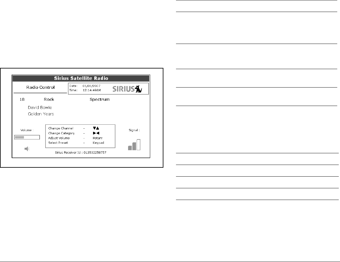
G-Series Reference Manual 170
14.1 Using Sirius Radio
As well as using the G-Series to control your radio, you can set up
parental locks to limit access to selected channels and create alerts
to tell you when a favourite song is being played.
To start using Sirius radio
1. Press MENU.
2. On the Setup Menu, select Sirius Satellite Radio.
The Sirius Radio Control screen opens:
Information contained on the Sirius Radio Control screen includes:
• Current channel name, number and category
• Play data for the current channel
• Date and time
• Receiver ID and signal strength
Use the softkeys and trackpad to control audio functions. Use the
rotary controller to adjust volume.
The toolbar gives you access to the functions outlined below.
14.2 Tuning to a channel
From the Sirius Control screen, you tune to channels using the
trackpad or the alphanumeric keys.
14.3 Browsing channels
The browse function allows you to view play data for channels with-
out tuning to them.
MUTE ON/OFF Controls the mute setting.
PRESETS Displays a list of preset channels and the full
channel list with modify options. Use the
trackpad or rotary controller to scroll through
the list of presets.
SETUP CHANNELS Gives access to the Edit Presets, Edit Alerts,
Edit Channel Access, Scan Channels
softkeys.
ALERTS Lets you set up an alert to tell you when favou-
rite songs or artists are played on any channel.
BROWSE Scroll to view play data and to select channels,
presets, or categories.
Trackpad up Next channel.
Trackpad down Previous channel.
Trackpad left First channel in the previous category.
Trackpad right First channel in the next category.

171 Chapter 14: Sirius Audio (US only)
To browse channels
1. On the Sirius Audio Control screen, press the BROWSE
softkey.
Pressing this key displays the Channel List or Preset List for
browsing. Toggle between the two lists with the VIEW ALL/PRE
softkey.
2. Use the rotary controller or trackpad to scroll through the
channels.
3. Press the TUNE TO CHANNEL softkey (or the rotary controller)
to listen to the selected channel.
To go back to the Sirius Control screen, press OK or CANCEL.
Filtering categories from the browse
This feature allows you to choose a category from which to browse
channels; other categories are excluded from the browse.
To filter categories
1. On the Browse screen, press the FILTER BY softkey.
2. Press the SELECT CATEGORY softkey.
3. Using the trackpad or rotary controller, select the category you
want to browse.
4. Press OK.
14.4 Scanning channels
The Scan function automatically tunes to all channels in turn.
To scan channels
1. Press the SETUP CHANNELS softkey.
2. Select SCAN CHANNELS.
3. Use the SCAN ALL/PRE softkey to choose to scan all channels
or only preset channels.
4. Press SELECT to stop the scan and listen to the active
channel.
14.5 Hiding or showing channels and
categories
You can select particular channels and categories to be excluded
(hidden) from the Browse and Scan sequences.
To hide or show a channel or category
1. Press the SETUP CHANNELS softkey.
2. Select EDIT CHANNEL ACCESS.
3. In the channel list, select the channel you want to hide. If you
want to hide a category, select any channel in that category.
4. Toggle between hidden and shown states with either the
CHANNEL SHOWN/HIDDEN or CATEGORY SHOWN/
HIDDEN softkeys.
14.6 Presets
You can assign up to 18 channels to presets to make tuning, scan-
ning and browsing easier. To assign a channel to a preset, use the
PRESETS softkey from the main control screen or the EDIT PRE-
SETS softkey from either of the following screens:
• Setup channels
• Browse channels
At the Edit Preset Channels screen you can select a preset and
assign a channel to it, move the assigned channel to a different
preset, or delete the assigned channel.
Toggle between the Preset Channels list and the Channel List
either by using the trackpad (left/right) or by pressing the appropri-
ate softkey.
To assign a channel to a preset
1. Select an unused preset number from the Preset List.
2. Press the ASSIGN NEW CHANNEL softkey.
3. Select the target channel from the Channel List.
4. Press the ASSIGN TO PRESET softkey.

G-Series Reference Manual 172
Note: If the preset you want to use already has a channel
assigned to it, delete the preset first.
To delete a channel from a preset
1. In the Preset Channels list, select the preset you want to clear.
2. Press the DELETE CHANNEL softkey.
To move a channel to a new preset
1. Use the rotary controller or trackpad to select the preset you
want to move.
2. Press MOVE TO NEW PRESET.
3. Scroll to the preset you want to move the channel to.
4. Press MOVE TO NEW PRESET.
Note: You can overwrite a channel that has already been assigned
to a preset, but you will be prompted to confirm the action.
14.7 Parental locking
You can set up blocks on selected channels so that they can only
be played if a correct password is entered. Parental locking must
be enabled for the blocks on your selected channels to be effective.
By default, blocking is not enabled.
To enable blocking
1. Press the SETUP CHANNELS softkey.
2. Press the PARENTAL LOCK ON/OFF softkey so that ON is
highlighted.
To set up a password
1. Press the SETUP CHANNELS softkey.
2. Press the PARENTAL LOCK softkey to highlight ON.
3. At the Password Setup screen, enter and confirm your pass-
word and hint.
You can also access the password entry screen by pressing EDIT
CHANNEL ACCESS then CHANNEL ENABLED/LOCKED.
To change an existing password
1. Press the EDIT CHANNEL ACCESS softkey.
2. Press the EDIT LOCKOUT PASSWORD softkey.
3. Enter your old password, then the new password and hint.
To block a channel
1. Press the SETUP CHANNELS softkey.
2. Press the EDIT CHANNEL ACCESS softkey.
3. In the Channel List, select the channel you want to block.
4. Press the CHANNEL ENABLED/LOCKED to highlight
LOCKED.
5. Repeat steps 3-4 for each additional channel you want to block.
6. When you blocked all the channels you want, press the CLEAR
key.
7. Ensure the parental lock is on (ON is highlighted on the
PARENTAL LOCK ON/OFF softkey).
8. At the prompt, enter your password.
Blocked channels remain visible in channel lists, but you cannot
select them with the trackpad and they are ignored by the scan
function. They are marked as locked by an icon next to the channel
name.
Entering passwords
If you select a blocked channel from the channel list or want to
block a channel when the parental lock is on, you will be asked to
enter the password.
After three incorrect attempts, the system displays your password
hint.
14.8 Favourite song alerts
The favourites feature alerts you when a favourite song or artist is
playing on any channel. You can define up to ten favourites using
the Alerts softkey.

173 Chapter 14: Sirius Audio (US only)
To enable favourite alerts
1. Press the ALERTS softkey to open the Edit Alerts screen.
2. Use the ALERTS ON/OFF softkey to toggle favourite alerts on
and off.
To set up a song or artist alert
• Press the ALERTS softkey to open the Edit Alerts screen. This
screen shows ten favourites and the song playing currently.
• You can delete a favourite from the list, add the current song or
artist to the list or switch the favourites alert off.
• You can also mark a channel or song as a favourite by pressing
the ASSIGN TO ALERT softkey while scanning.
When alerts are turned on and the system detects one of your
favourites being played on any channel, it will display an alert and
sound the alarm.
• To tune to the channel playing the song, press TUNE TO
CHANNEL. To ignore the alert, press CLEAR ALERT.

G-Series Reference Manual 174

15
Chapter 15: Course Deviation Indicator
With the G-Series system receiving accurate heading and position data, you can use the Course Deviation
Indicator (CDI) to monitor your course and help you steer to a target waypoint.
Chapter contents
• 15.1 The CDI display on page 176
• 15.2 Using the CDI application on page 176
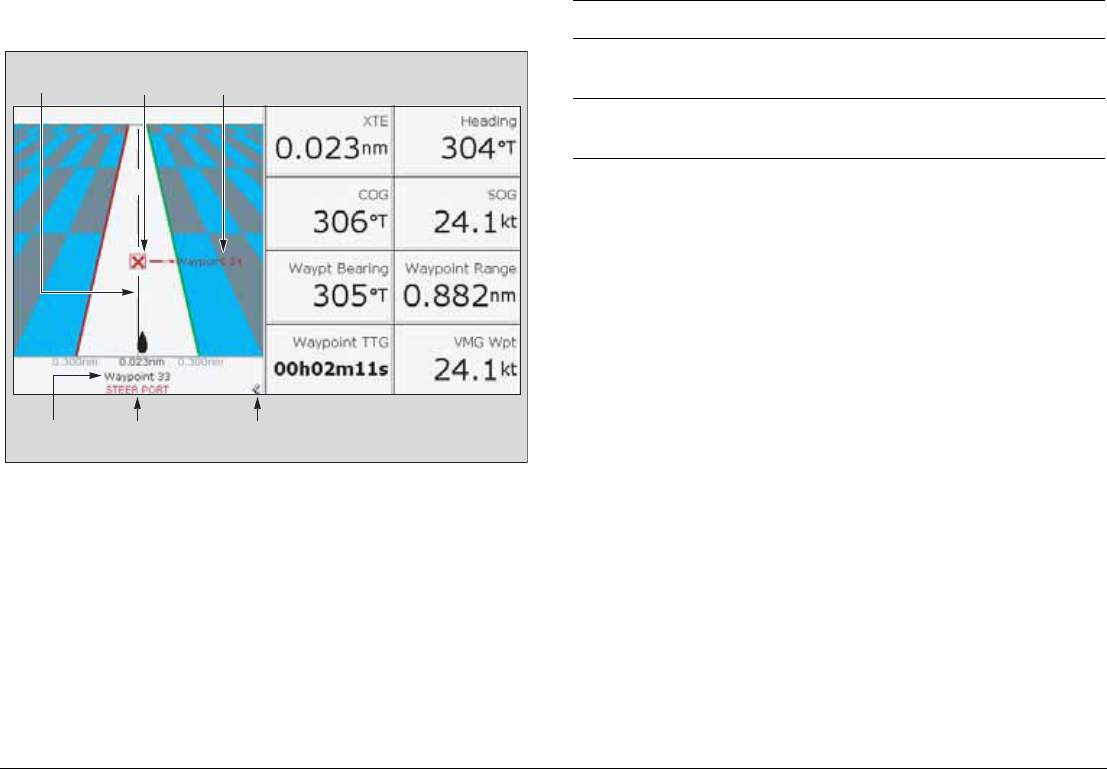
G-Series Reference Manual 176
15.1 The CDI display
The CDI gives you a ‘rolling road’ representation of your progress,
with navigation data displayed alongside.
The rolling road covers an area of sea that corresponds to the
Cross Track Error (XTE) limits specified in the Setup menu.
Steering instructions
The steering instructions below the rolling road tell you what correc-
tion is needed to maintain your course and arrive at the target
waypoint.
Indicator-arrows either side of the steering instruction (pointing
towards the centre line) tell you how great or small the error is. The
greater the error, the greater the number of arrows.
Correct your course by steering in the direction indicated by the
arrows.
15.2 Using the CDI application
To use the CDI, you need to select a page set that includes a CDI
window. For more information about page sets, see Choosing page
sets on page 25.
To open the CDI application
1. Press and hold the PAGE button to open the Select Page Set
window.
2. Select a page set that includes the CDI application.
D9515_1
On course
line
Target way-
point name
Target
waypoint
Direction to steer
to maintain course
D9515-1
Direction
to steer
Direction of
next waypoint
Instruction Cause
STEER
STARBOARD
XTE error to port is more than a 1/4 of the maximum
XTE error limit in the Setup menu
STEER PORT XTE error to starboard is more than a 1/4 of the
maximum XTE error limit in the Setup menu
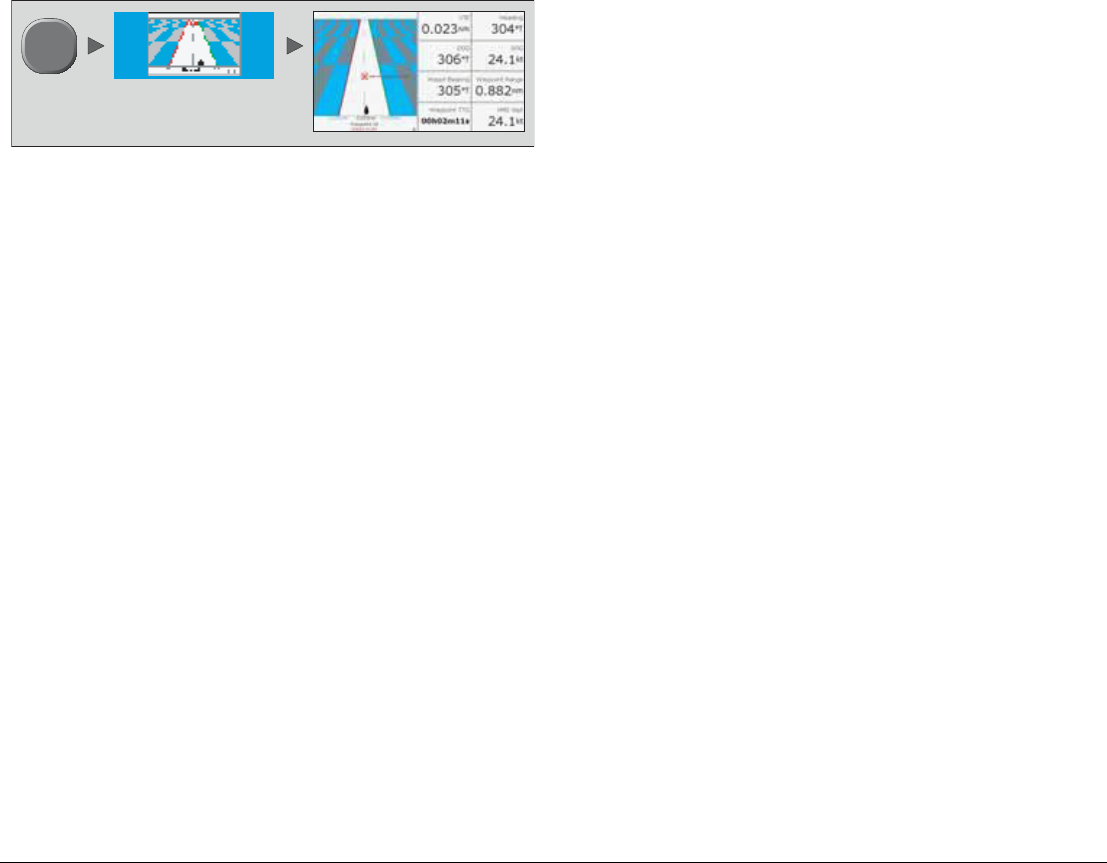
177 Chapter 15: Course Deviation Indicator
3. Select a page that includes a CDI window.
D9517-1
PAGE
Select page including
CDI window

G-Series Reference Manual 178

16
Chapter 16: The Data Application
The data application shows you data that is generated by the G-Series system, or that is received from
attached instruments.
Chapter contents
• 16.1 The data display on page 180
• 16.2 Using the data application on page 180
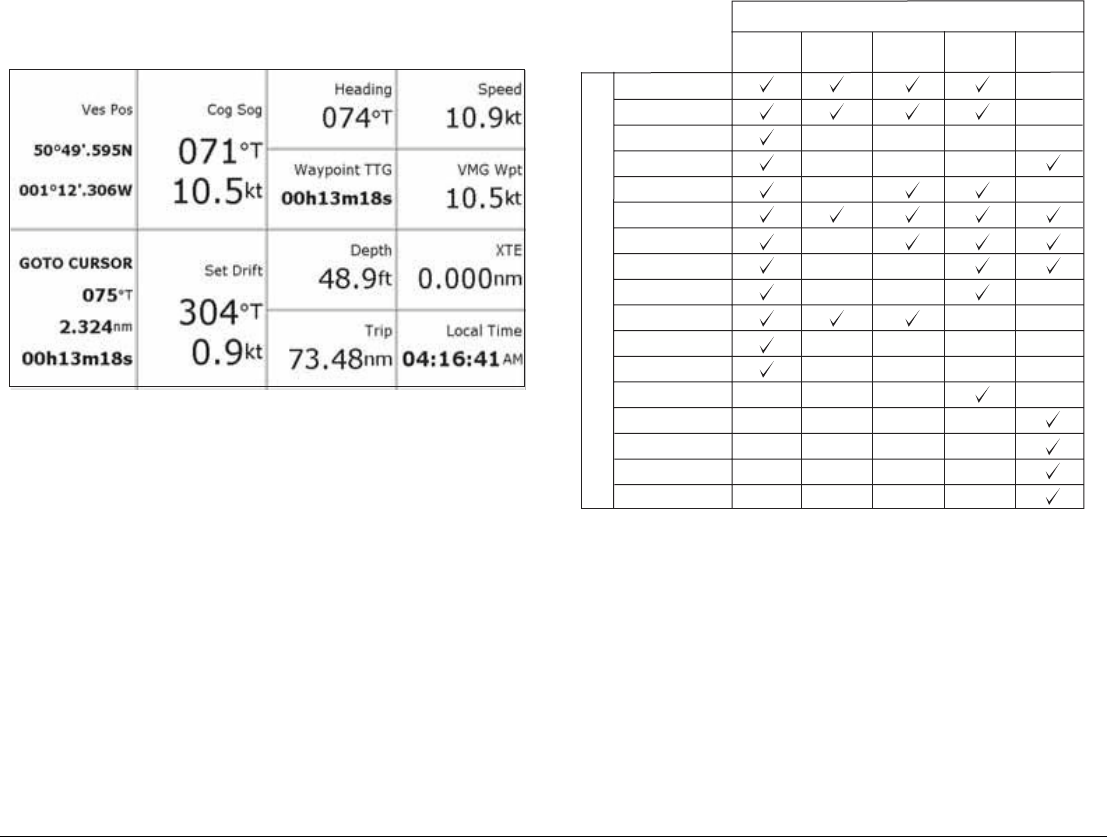
G-Series Reference Manual 180
16.1 The data display
The data screen gives you access to five preconfigured data
panels.
16.2 Using the data application
To use the data application, you need to select a page set that
includes a data window.
You can select a panel of pre-configured data or customize any
panel to display the data of your choice. Pre-configured data panels
include data associated with G-Series navigation, waypoint, route,
fishing or sailing functions.
For more information about page sets, see Choosing page sets on
page 25.
To select a pre-configured data panel
1. Press the ACTIVE button.
2. Press the appropriate softkey.
Customizing data panels
You can customize each panel by changing any or all of the follow-
ing attributes:
• Panel name.
• Size and number of data cells.
D9513 1
Vessel position
Active waypoint
TTG
VMG - Waypoint
Depth
Cog Sog
Heading
Speed
Set/Drift
XTE
Trip
Local time
Sea temperature
Ground wind
App wind
True wind
VMG wind
Panel Type
Navigation Waypoint Route Fishing Sailing
D8950_1
Data content

181 Chapter 16: The Data Application
• Cell data: a cell can contain any transducer- or internally-calcu-
lated data that is available on NMEA or SeaTalk. Additional
data includes a compass gauge, a distance log and four reset-
table trip counters.
• Type of display: data can be shown in numerical, gauge or
graphical format as appropriate.
To rename a panel
1. Press the MENU button and select Panel Setup Menu.
2. Select the panel you want to rename.
3. Press the RENAME softkey.
4. Set the name.
5. Press OK.
To select data for a cell to contain
1. Press the MENU button and select Panel Setup Menu.
2. Select the cell you want to assign data to.
3. Press the SELECT DATA softkey.
4. Select the data type and format.
5. Press OK.
To split cells
1. Press the MENU button and select Panel Setup Menu.
2. Select the cell you want to split.
3. Press the vertical or horizontal SPLIT CELL softkey as
appropriate.
The direction in which the selected cell will be split is indicated by
an arrowhead on the softkey label.
To merge cells
1. Press the MENU button and select Panel Setup Menu.
2. From the pair of cells you want to merge, select either the left-
or upper-most cell.
3. Press the vertical or horizontal MERGE CELLS softkey as
appropriate.
The direction in which the cells will be merged is indicated by an
arrowhead on the softkey label.

G-Series Reference Manual 182

17
Chapter 17: Engine Monitor
The engine monitor lets you view information from up to three compatible engines in the form of gauges and
digital data.
Engines with a J1939 or NMEA 2000 interface are compatible.
Chapter contents
• 17.1 The engine monitor on page 184
• 17.2 Setting up the engine monitor on page 184
• 17.3 Available data on page 184
• 17.4 Engine monitor alarms on page 185
See also…
www.raymarine.com for information about compatible engines and related software updates.
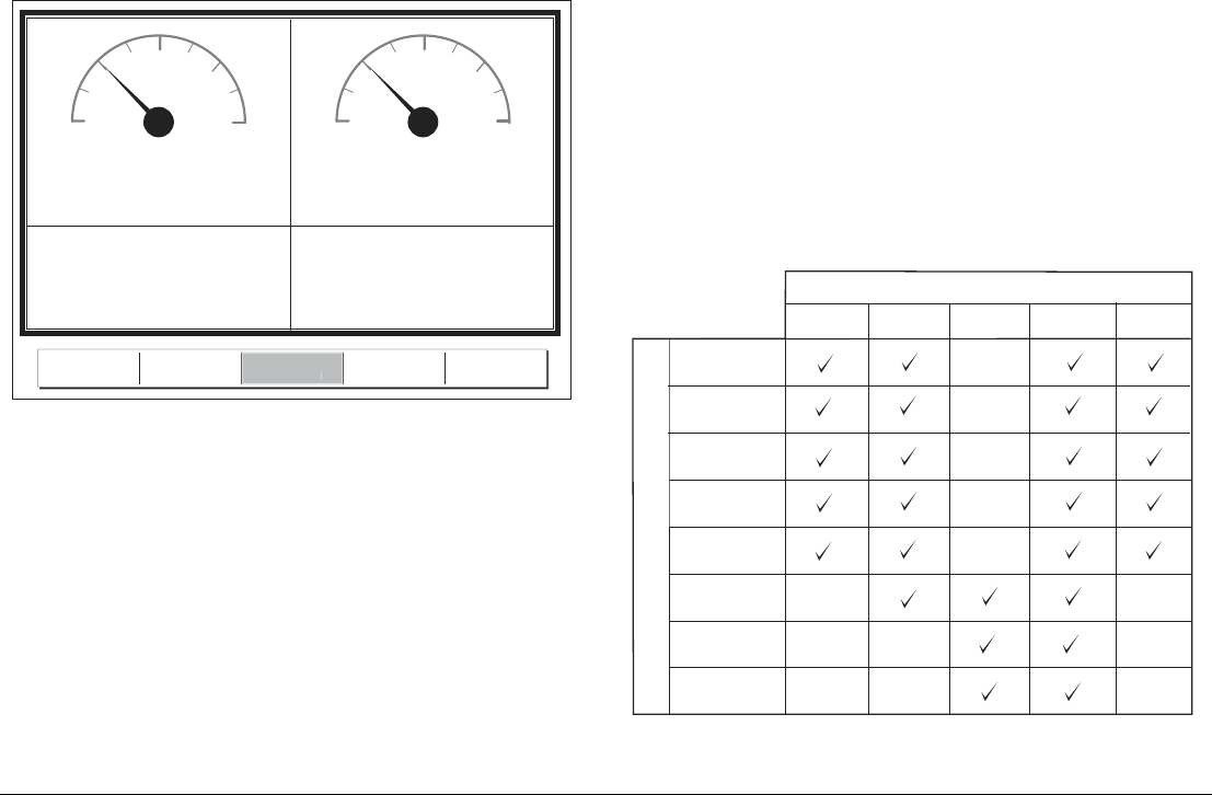
G-Series Reference Manual 184
17.1 The engine monitor
The engine monitor toolbar gives you access to five preconfigured
data panels. You can customize these panels in the same way as
you do in the data application. For more information about custom-
izing data panels, see Customizing data panels on page 180.
17.2 Setting up the engine monitor
Before you use the engine monitor, you need to:
• Customize a page set to include an engine monitor window.
• Set the number of engines and the maximum tachometer range
to reflect your particular vessel.
For information about how to do customize page sets, see Choos-
ing page sets on page 25.
To set engine and tachometer values
1. Open the Panel Setup Menu (with an engine monitor window
active, press the MENU button).
2. Set the number of engines.
3. Set the maximum tachometer range.
Temperature and fuel units
Engine temperature units (°F or °C) and fuel units (liters, imperial
gallons or US gallons) are defined in the System Setup Menu under
Units Setup.
17.3 Available data
The table below summarizes the data contained in each pre-config-
ured data panel (available on the softkeys).
0 0
25 25
50 50
75 75
100 100
% %
Fuel 1 Fuel 2
Fuel Rate
11.61 gals/h
Fuel Rate
13.95 gals/h
D7516_3
ENGINE ENGINE &
FUEL
ENGINE &
RESOURCES TWIN ENGINE
FUE
L
R
ESOURCE
S
Panel Type
D8953_1
Data content
Tacho &
engine hours
Oil pressure
Engine coolant
temperature
Boost
pressure
Alternator
Fuel level
(tanks 1 & 2)
Fuel rate
Total fuel
Engine Engine
& fuel
Fuel
resources
Engine &
resources
Multi
engines (3)

185 Chapter 17: Engine Monitor
17.4 Engine monitor alarms
The engine monitor triggers an alarm (over NMEA/SeaTalk2) when
a problem is detected.
If this occurs, check the engine monitoring system and if necessary
refer to the documentation supplied with your engine system. Press
ACKNOWLEDGE to silence the alarm.
Note: When engine monitoring is active, all other system alarms
remain active.

G-Series Reference Manual 186

18
Chapter 18: System Setup and Customizing
This chapter details the settings available on the system Setup menu. For instructions on how to use the
menus, see Operating Principles on page 21.
Chapter contents
• 18.1 Page sets on page 188
• 18.2 Databar on page 188
• 18.3 Compass bar on page 189
• 18.4 Compass Setup on page 190
• 18.6 System-wide settings on page 191
• 18.5 GPS Setup on page 190

G-Series Reference Manual 188
The system Setup menu is split into sections: application-specific,
external equipment and system-wide.
Application-specific menus are context-sensitive. The menu that
opens is appropriate to the application in the active window when
you press the MENU button.
• For application-specific setup menu details, refer to the appro-
priate application chapter of this book.
External equipment menus provide options to set up external
equipment that is connected to your G-Series system. This might
include AIS, Navtex, GPS or Compass equipment; the options
available on the menu depend upon what is connected.
System setup menus control functions throughout the system.
When you first power on your system, default values are used. The
tables that follow show the sub-menus, settings and options that
are available to customize those defaults.
Changes you make on one display affect all displays in the net-
work, with the exception of Display Setup, Databar Setup and
Select Page set.
18.1 Page sets
If none of the default page sets suit you, you can edit them to dis-
play the application and page layouts you want.
To configure a page set
1. Open the system Setup menu.
2. Open the Select Page Set screen.
3. Highlight the page set you want to edit.
4. Press the appropriate softkey:
EDIT PAGE SET
RENAME PAGE SET
RESET TO DEFAULT PAGES
5. Follow the on-screen instructions for the option you selected.
6. Press OK.
18.2 Databar
Configuration options available on the Databar Setup screen
include:
•Position on screen
At the top or on the side of the display.
•Size
For the top position, set to large or small.
•Data displayed
Note: The databar configuration applies only to the display on
which you are working.
To configure the databar
1. Open the system Setup Menu.
2. Select Databar Setup then Configure.
3. Press the appropriate softkey:
ADD DATA
REMOVE DATA
MOVE DATA
4. Follow the on-screen instructions.
5. Press OK when complete.

189 Chapter 18: System Setup and Customizing
The table below lists the data available.
Log trip
You can view the total distance travelled (Log) and the distance of
your current journey (Trip) based on your speed through water
(STW) from a speed transducer.
In addition you can include in your data application or databar,
ground log and four ground trip counters based on your GPS posi-
tion. These counters are updated every minute and can be
individually reset from the system setup menu.
If the GPS fix is lost or if the system simulator is switched on, the
system will pause the ground log and trip counters. When the GPS
fix returns, or the system simulator is switched off, the ground log
and trip counters resume.
18.3 Compass bar
The compass bar gives you a continuous readout centred on your
current heading or course over ground (COG). Arrows at either end
of the bar indicate current steer direction.
When displayed, it replaces the databar and is always positioned at
the top of the screen.
Data groups Data (abbreviations in brackets)
VESSEL Vessel position (Ves Pos)
Course over ground/Speed over ground
(COG/SOG)
Heading
Speed
Wind velocity made good (VMG Wind)
Waypoint velocity made good (VMG Wpt)
Log trip
Log
Trip
Ground Log/Trip 1
Ground Log
Ground Trip 1
Ground Trip 2
Ground Trip 3
Ground Trip 4
Rudder
NAVIGATION Cross track error (XTE)
Waypoint (WPT)
DEPTH Depth
ENVIRONMENT Pressure
Air temperature (Air Temp)
Sea temperature (Sea Temp)
Set drift
WIND True wind
Apparent wind (App Wind)
Ground wind
TIME AND DATE Local time
Local date
CURSOR POSITION Cursor position (Csr Pos)
TRANSDUCER STATUS Transducer status
Data groups Data (abbreviations in brackets)
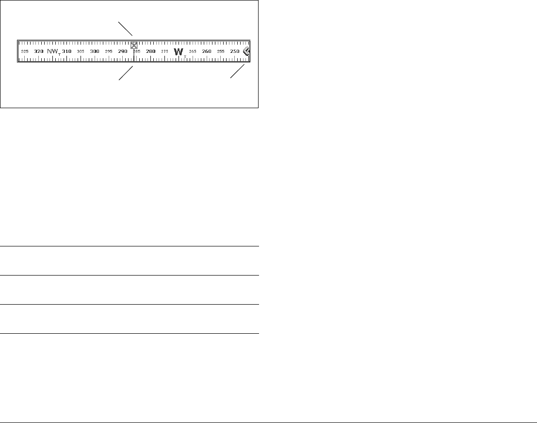
G-Series Reference Manual 190
• In heading mode, the bearing marker is RED.
• In COG mode, the bearing marker is GREEN.
• When you use the compass bar with an active waypoint, the
bearing marker is BLUE and the active waypoint symbol indi-
cates the bearing to your waypoint.
You turn the compass bar on and off from the data toolbar.
To turn the compass bar on and off
1. Press the DATA button.
2. Use the DATABAR softkey to turn the compass bar on or off.
Note: When the compass bar is displayed the transducer icons
remain visible in the top-right section of the screen.
Compass bar setup
The compass bar is set to open in heading mode. To change this
setting, press the MENU button and go to the Databar Setup menu
where you can select either Heading or COG.
Note: If a man overboard (MOB) alarm is activated while the
compass bar is open, the compass is replaced with the
MOB toolbar. The compass bar returns when you cancel the
active MOB.
18.4 Compass Setup
This option can be used to linearize, or ‘swing’, a Raymarine ST80
active compass or Smart Heading sensor connected on SeaTalk.
Note: You calibrate an autopilot compass through the autopilot
control head.
To linearize your compass
1. Select Compass Setup.
2. Press the LINEARIZE COMPASS softkey.
3. Follow the on-screen instructions.
4. Use the rotary controller to fine-tune heading alignment.
18.5 GPS Setup
The GPS is used to position your boat on the chart. You can set up
your Global Positioning System (GPS) and check its status from
the GPS Status option in the Setup Menu.
For each tracked satellite, this screen provides:
• satellite number
• signal strength bar
• status
• azimuth angle
• elevation angle
• A sky-view to show the position of tracked satellites
ON Displays the standard databar, at the top or side of the
screen depending on your setup options.
COMPASS Replaces the standard databar with the compass bar,
displayed along the top of the screen.
OFF Removes both the databar and the compass bar from
your display.
Steer directionBearing marker
Active waypoint
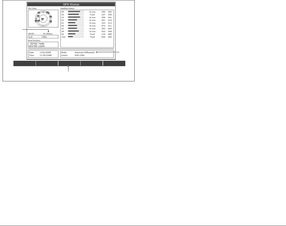
191 Chapter 18: System Setup and Customizing
GPS accuracy depends upon the parameters shown, especially the
azimuth and elevation angles which are used in triangulation to cal-
culate your position.
Horizontal Dilution of Position (HDOP) is a measure of GPS accu-
racy; a higher figure signifies a greater positional error. In ideal
circumstances, the figure should be in the region of 1.0.
Satellite differential system
Select the satellite group(s) appropriate to your area using the
Other Set Up softkey:
• WAAS - United States
• EGNOS - Europe
• MSAS - Japan
• GAGAN - India
Note: The EGNOS, MSAS and GAGAN systems may not be
active. Check with your local government for operational
status.
COG/SOG filter
Set the COG/SOG filter to the level appropriate to your use and to
the level of oscillation being experienced by the GPS:
•HIGH for trawling or when there is a high level of oscillation.
•MEDIUM for general use.
5. LOW when travelling at speed.Display Setup
18.6 System-wide settings
The following tables detail the options available under each of the
system-wide menu items.
DIFF SET UP OTHER SET UP RESTART GPS
DIFF GPS
ON OFF
D6809_3
Actual mode
GPS reporting
(No Fix, Fix, D
Fix or SD Fix)
Mode
selected
by GPS
Only available if connected to
Raymarine landbased GPS e.g. 114

G-Series Reference Manual 192
System Setup menu
MENU ITEM OPTIONS
Position Mode
Controls whether the position is expressed in latitude and
longitude co-ordinates or Loran TDs.
Lat/Long
TD’s
TD Setup
If the Position Mode is set to TD’s, this function controls the
selected chain identifier, slave and ASF.
Various
Simulator
ON - allows operation of display without data from antenna
and/or external data sources.
Demo - a series of slides with descriptions to demonstrate
the various system functions.
OFF
ON
Demo
Bearing Mode
Mode of all bearing and heading data displayed. This does
not affect how the chart or radar are drawn.
True
Magnetic
MOB Data Type
Selects whether position data or dead reckoning displayed
on screen. Assuming your boat and the MOB are subject to
same tide and wind effects, dead reckoning normally gives
a more accurate course.
Dead
Reckoning
Position
Variation Source
This allows you to compensate for the naturally occurring
offset of the earths magnetic field. When set to AUTO, the
value the system would use (or is using) is noted in the
menu e.g. 40W. To enter your own variation value, set to
MANUAL.
Auto
Manual
Manual variation
If Variation Source is set to MANUAL then use this setting
to enter the variation value. This value is transmitted to any
other SeaTalk instruments.
0°E
Range 0 - 30º
east/west
Language
Selected language used for screen text, labels, menus,
options and display format for lat/lon position information.
Selection
available will
vary according
to your
location.
Extended Character Set
Controls whether additional accented characters are made
available when you are entering text.
OFF
ON
Ground Trip Reset...
Resets the chosen ground trip distance counter to zero. Ground Trip 1 -
4 Reset
Settings Reset
Resets all system setup menus, including page sets and the data bar to the
factory default. Waypoints, routes and tracks are NOT removed.
Settings and Data Reset
Resets all system setup menus, including page sets and the data bar to the
factory default. Waypoints, routes and tracks are deleted.
Date /Time Setup See sub-menu
below
Units Setup See sub-menu
below
System Integration See sub-menu
below
Waypoint Password Set-up...
Allows you to set up a password to protect access to your
waypoint and route databases.
MENU ITEM OPTIONS

193 Chapter 18: System Setup and Customizing
Date/Time Setup Menu
Units Setup Menu
MENU ITEM OPTIONS
Date Format
Displays date as day/month/year or month/day/year
mm/dd/yy
dd/mm/yy
Time Format
Displays either 12 or 24 hour clock
12hr
24hr
Local Time Offset
Specify local time in increments of 0.5 hours (+/- 13)
from the Universal Time Constant. Use rotary control
for 0.5hr increments and trackpad to individually adjust
the value of the tens, units, and tenths - system rounds
to nearest 0.5 hr.
+/- 13hrs from UTC
MENU ITEM OPTIONS
Distance Unit
Choose the units you require distances to be displayed
in.
NM
Miles
km
Speed Units
Choose the units that you require speed to be
measured in.
Knots
MPH
KPH
Depth Units
Choose the units that you require depths to be
measured in.
Meters
Feet
Fathoms
Temperature Units
Select required temperate unit.
Fahrenheit
Celsius
Pressure Units
Select required pressure unit.
Bar
Psi
Kpa
Volume Units
Select required volume unit.
US Gallons
Imp Gallons
Litres
MENU ITEM OPTIONS

G-Series Reference Manual 194
System Integration Setup Menu
Note: If AIS or Navtex has been set on any display in the system,
the menu options will be available on all displays. Navtex
and AIS are available simultaneously.
Alarm Setup Menu
The Alarm Setup Menu has five sub-menus:
• System Alarms Setup
• Navigation Alarms Setup
• Radar Alarms Setup
• Fishfinder Alarms Setup
• AIS Alarms Setup
System Alarms Setup
System alarms sound in all applications.
MENU ITEM OPTIONS
DSC Message
When set to ON, details of distress DSC messages are
displayed on screen
ON
OFF
SeaTalk Alarms
When set to enabled, all SeaTalk system alarms are
received and displayed on the chartplotter.
Enabled
Disabled
Data Master
When set to ON, the display you are working on is
defined as the master.
ON
OFF
Bridge NMEA Heading
Used to prevent NMEA heading data being bridged
onto the SeaTalk bus. Switch this function off if you are
using MARPA with an external fast heading sensor.
ON
OFF
NMEA Output Setup
Allows you to switch off individual NMEA out sentences
APB, BWC, BWR,
DBT, DPT, GGA,
GLL, MTW, RMA,
RMB, RMC, RSD,
RTE, TTM, VHW,
VLW, VTG, WPL,
ZDA
NMEA Port Setting
Select the appropriate setting dependent on the equip-
ment attached to the NMEA port for each individual
display.
When Navtex 4,800 or 9,600 selected, the option to
view the Navtex message list is available.
NMEA 4,800
Navtex 4,800
Navtex 9,600
AIS 38,400
MENU ITEM OPTIONS
Anchor Alarm
Switches the anchor alarm on or off.
OFF
ON
Anchor Alarm Radius
If the Anchor Alarm is set to ON, an alarm is triggered
when you drift from your anchor position by more than
the specified distance.
0.01 - 9.99 nm
0.10nm
(or equivalent in the
selected Distance
Unit)
Timer
Switches the countdown timer alarm on or off
OFF
ON
Timer Period
If the Timer is set to ON, the system counts down from
the time you specify. An alarm is triggered when zero is
reached.
00h01m - 99hrs
59mins
00h00m
Alarm Clock
Switches the alarm clock on or off.
OFF
ON
Alarm Clock Time
If the Alarm Clock is set to ON, an alarm is triggered
when the time you specify is reached.
00.01 - 24:00hrs
00:00

195 Chapter 18: System Setup and Customizing
Navigation Alarms Setup
Navigation alarms will sound in any application when you are
navigating.
Radar Alarms Setup
These alarms will only sound when you are in the radar application.
Note: If a radar is not detected, the alarm setup windows are
grayed out.
Temperature Alarm
If this alarm is set to ON, an alarm is triggered if the
temperature moves into or out of the range that you
have specified in Lower Temperature Limit /Upper
Temperature Limit.
OFF
ON
Lower Temperature Limit
Specifies the lower limit of the sea temperature range
that is to trigger the Temperature Alarm.
60°F
0°-99.8°F
Upper Temperature Limit
Specifies the upper limit of the sea temperature range
that is to trigger the Temperature Alarm.
75°F
0.2°-99.9°F
MENU ITEM OPTIONS
Arrival Alarm Radius
The distance from the target waypoint or the closest
point of approach to the target waypoint that triggers the
arrival alarm to sound.
0.1nm
0.01 - 9.99nm
Offtrack Alarm
Switches the off-track alarm on or off
OFF
ON
Offtrack Alarm XTE
If the Offtrack Alarm is set to ON, an alarm is triggered
when the XTE for any current navigation, exceeds the
value that you have specified.
0.3nm
0.01 - 9.99nm
(or equivalent in the
selected Distance
Unit)
MENU ITEM OPTIONS
MENU ITEM OPTIONS
Guard Zone Sensitivity
Ensure that this is not set too low or targets will be
missed.
50%
0 - 100%

G-Series Reference Manual 196
Fishfinder Alarms Setup Note: If a fishfinder is not detected, the alarm setup windows are
greyed out.
AIS Alarms Setup
Display setup
MENU ITEM OPTION
Fish Alarm
Switches the fish alarm on or off.
OFF
ON
Fish Alarm Sensitivity
If the Fish Alarm is set to ON, an alarm is triggered
when the fish return strength reaches the sensitivity that
you specify.
5%
10% - 100%
Fish Alarm Depth Limits
If the Fish Alarm and this alarm is set to ON, an alarm is
triggered (2 beeps) if any target meets the sensitivity
level and is within the Shallow Fish Limit and Deep Fish
Limit that you specify.
OFF
ON
Shallow Fish Limit
Specifies the lower value for the Fish Alarm Depth LImit.
2ft
(0002ft - 1000ft)
Deep Fish Limit
Specifies the upper value for the Fish Alarm Depth LImit
1000ft
(0002ft - 5000ft)
Shallow Depth Alarm
Switches the shallow depth alarm on or off.
If a DSM is not connected, this cannot be set.
OFF
ON
Shallow Depth Alarm Value
If the Shallow Depth Alarm is set to ON, an alarm is trig-
gered if the depth drops below the value you specify.
5ft
(0002ft - maximum
range of transducer)
Deep Depth Alarm
Switches the deep depth alarm on or off.
If a DSM is not connected, this cannot be set.
OFF
ON
Deep Depth Alarm Value
If the Deep Depth Alarm is set to ON, an alarm is trig-
gered if the depth exceeds the value that you specify.
Dangerous Targets Alarm
Switches the alarm for dangerous targets to on or off.
When OFF, the AIS alarm off icon is displayed in the status
bar.
OFF
ON
AIS Alarm List
Details the identity, description, time and acknowledge-
ment of alarm messages received from an AIS receiver.
MENU OPTION OPTIONS
Soft key Autohide
Controls whether the toolbar is automatically hidden if
not used for a period of 10 seconds. Pressing any key
re-displays it.
OFF
ON
Cursor Autohide
Controls whether the cursor is automatically hidden if
not used for 10 seconds. Pressing any key re-displays
the cursor.
OFF
ON
Key beep
Controls whether a noise is made when you press a
key.
OFF
ON
Text size
Controls the size of the text on the screen
Small
Large

19
Chapter 19: CompactFlash Cards and Managing Data
CompactFlash cards expand the capabilities of the G-Series system. They provide:
•Detailed cartographic information
Obtain cartographic information using Navionics® chart cards. To check the current availability of Navion-
ics chart card types, visit www.navionics.com or www.navionics.it.
•Archiving and updating
Store waypoints, routes and tracks and update system software.
•Saving data
Save waypoint, route and track data for use on other equipment like personal computers.
Chapter contents
• 19.1 Cautions on page 198
• 19.2 Card insertion and removal on page 198
• 19.3 Saving and retrieving data on page 199
• 19.4 Sending and receiving data from a personal computer on page 199
• 19.5 Password protecting your waypoints on page 200

G-Series Reference Manual 198
19.1 Cautions
CompactFlash Card Installation
When installing CompactFlash cards ensure that the card is
fitted the correct way around. DO NOT try to force the card
into position as this may result in irreparable damage to the
card.
Water Ingress
To prevent the ingress of water and consequent damage to
the unit, ensure that the chart card door is firmly closed at
all times. This can be confirmed by an audible click.
Card Removal
DO NOT use a metallic instrument such as a screwdriver or
pliers to help you remove a card, as doing this can cause
irreparable damage.
Card writing
CompactFlash cards can be damaged if they are removed
from the unit during either a read or write operation. A
warning is displayed during write operations. The unit is
continually reading the card. It is therefore essential that
before removing the card you follow the correct procedure
to stop access to the card.
Note: Raymarine recommends the use of SanDisk Standard
Compact Flash memory for reliability.
19.2 Card insertion and removal
You can remove and insert cards while a chart is displayed pro-
vided that you follow the correct procedure. Chart information is
retained on-screen until the chartplotter redraws the screen; for
example, when you pan outside the current area, or use the
RANGE button to change the chart scale.
Cartographic data is available on any monitor.
Card removal
Only remove the card while the CF Card Removal message is dis-
played. This is opened through the setup menu, documented
below. Once the message is closed, the card should no longer be
removed
If you try to remove a card without accessing the setup menu, a
blue screen and warning message is displayed and the unit must
be restarted.
To insert a CompactFlash card
1. Check that you are using the correct type of card (see Important
Information, at the beginning of this manual).
2. Open the chart card door.
3. Insert the card with the lip of the card facing inwards. It should
position easily. If it does not, DO NOT force it but check the
direction in which the lip is facing.
4. Gently press the card home.
5. To prevent the ingress of water and consequent damage, close
the chart card door and press firmly until it clicks.
To remove a CompactFlash card with the unit powered
up
1. Press the MENU button to open the system Setup menu.
2. Select Remove CF Card.
3. When you see the message telling you it is safe to do so,
remove the card. Do not remove a card until you see the
pop-up saying it is safe to do. Otherwise you could lose
data.
4. Open the chart card door.
5. Grip the card and pull to remove it from its slot.
6. To prevent water damage, close the chart card door and press
firmly until it clicks.
7. Press OK.
To remove a CompactFlash card with the unit powered
down
1. Open the chart card door.

199 Chapter 19: CompactFlash Cards and Managing
2. Grip the card and pull to remove it from its slot.
3. To prevent water damage, close the chart card door and press
firmly until it clicks.
19.3 Saving and retrieving data
The system can save up to 3000 waypoints, 150 routes and 15
tracks in database lists. Once this number is reached, you need to
archive data to a CompactFlash card for safe-keeping or retrieval at
a later date.
Alternatively, you can transfer data to another instrument or PC
using SeaTalkhs or NMEA. When navigation is active, you can also
receive waypoints, routes and tracks from a PC, other SeaTalkhs,
SeaTalk and NMEA instruments (see page 199).
Raymarine strongly recommend that you save data to a separate
CompactFlash card and not to a Navionics card containing
cartography.
To save data to a CF card
1. Make sure the correct card is inserted.
2. Press the DATA button.
3. Press the ARCHIVE AND TRANSFER softkey.
4. Press the SAVE TO CARD softkey.
5. Select the data list you want to save on the SELECT LIST
softkey.
6. Define the data you want to save by pressing the appropriate
softkey.
To retrieve information from a CF card
1. Insert the appropriate card.
2. Press the DATA button.
3. Press the ARCHIVE AND TRANSFER softkey.
4. Press the RETRIEVE FROM CARD softkey.
5. Select the data list you want to retrieve from.
6. Define the data you want to retrieve by pressing the appropriate
softkey.
If your selection is already found to exist on the system, a warning
message appears and the softkey labels change to give you the
options of retrieving as new, replacing the data or cancelling the
retrieving process.
To erase information from a CF card
1. Insert the appropriate card.
2. Press the DATA button.
3. Press the ARCHIVE AND TRANSFER softkey.
4. Press the ERASE FROM CARD softkey.
5. Select the list you want to remove data from.
6. Define the data to be deleted.
7. Press YES to confirm
19.4 Sending and receiving data from a
personal computer
You can transfer and retrieve waypoints or routes to and from
another instrument or PC using NMEA or SeaTalkhs.
With a RayTech 6.0’s planner you can transfer waypoints and
routes via a CF memory card. Such transfers require that the PC be
connected to the display’s NMEA port via a serial data cable. Ray-
Tech 6.0 will transfer waypoints and routes via SeaTalkhs.
To transfer or receive information from a personal
computer
1. Press the DATA button.
2. Press the ARCHIVE AND TRANSFER softkey.
3. Press TRANSFER ON NMEA.
4. Press the softkey that corresponds to the transfer you want to
perform.
To stop the transfer at any point, press STOP TRANSFER.

G-Series Reference Manual 200
19.5 Password protecting your
waypoints
If required, you can use password protection to control access to
your waypoint and route databases. Once you have set up a pass-
word, it must be entered to access the Password Setup sub-menu,
regardless of the whether Password Protection is set to ON or OFF.
Password confirmation
When Password Protection is enabled and you attempt to access a
password-protected function for the first time during a power-cycle,
the system asks for the password for the following functions:
• Access WPTS key functions. This does not affect the operation
of the MOB function.
• Access ROUTES soft key functions.
• Create a route from a track. All other track functions are
unaffected.
• Archive or transfer any waypoints.
• Enter the Waypoint Password Setup menu.
Disabled data/functions
When Password Protection is ON and you have not entered a
password you cannot:
• View details of waypoint and route databases.
• Edit waypoints or routes.
• Goto an existing waypoint.
• Follow a route.
• View waypoints on screen (even when the SHOW/HIDE status
is set to SHOW).
• View waypoint names on screen (even when WAYPOINT
NAME is set to ON).
• All other options including GOTO CURSOR are unaffected.
To set up a password
1. Open the system Setup menu.
2. Select System Setup.
3. Select Waypoint Password Setup.
4. Select Enable Password: ON.
5. Press OK.
6. Read and accept the warning.
7. Enter the password and confirm it.
8. If wanted, enter the password hint.
Note: The password is case sensitive.
The password is now set and protection enabled although access
to the waypoint and route functions remains available until you
restart your system.
To change the password
1. Select Change Password on the Waypoint Password Setup
menu.
Enabling and disabling password protection
Once you have set up a password on your system (see previous
section) you need to key in this password whenever you want to
change the status of the password protection feature.
To enable or disable password protection
1. Open the system Setup menu.
2. Select System Setup.
3. Select Waypoint Password Setup.
4. Enter your password. Remember it is case-sensitive.
5. Select Enable Password: OFF.
6. Press OK.
If you enter an invalid password more than twice within one power
cycle the system displays the password hint.

201 Chapter 19: CompactFlash Cards and Managing
There is no limit to the number of attempts to enter a valid pass-
word but if you forget your password, you need to perform a
Settings and Data Reset (see page 205) which will erase all way-
points in the unit’s memory.
Raymarine strongly recommends that you regularly save your way-
points, routes and tracks to a CF memory card.

G-Series Reference Manual 202

20
Chapter 20: Maintenance and Troubleshooting
This chapter provides information on maintaining and troubleshooting the G-Series system, and information
about getting assistance from Raymarine.
Chapter contents
• 20.1 Maintenance procedures on page 204
• 20.2 Resetting the monitor on page 204
• 20.3 Troubleshooting on page 205
• 20.4 Getting technical support on page 209
• 20.5 Navionics contact details on page 210
• 20.6 Sirius contact details on page 210

G-Series Reference Manual 204
20.1 Maintenance procedures
At regular intervals, carry out the following servicing procedures:
• Routine checks.
• Cleaning the Display.
Do not attempt any other servicing procedures.
Servicing and Safety
• Raymarine equipment should be serviced only by authorized
Raymarine service technicians. They will ensure that service
procedures and any replacement parts used will not affect
performance. There are no user serviceable parts in any
Raymarine product.
• Some products generate high voltages, so never handle the
cables or connectors when power is being supplied to the
equipment.
• When powered on, all electrical equipment produces electro-
magnetic fields. These can cause adjacent pieces of electrical
equipment to interact with one another, with a consequent
adverse effect on operation. In order to minimize these effects
and enable you to get the best possible performance from your
Raymarine equipment, guidelines are given in the installations
manual, to enable you to ensure minimum interaction between
different items of equipment, i.e. ensure optimum Electromag-
netic Compatibility (EMC).
• Always report any EMC-related problem to your nearest
Raymarine dealer. We use such information to improve our
quality standards.
• In some installations, it may not be possible to prevent the
equipment from being affected by external influences. Gener-
ally this will not damage the display, but it can lead to spurious
re-setting action, or momentarily may result in faulty operation.
• At the end of the useful working life of this product, it should
disposed of in accordance with local regulations.
Routine checks
Carry out the following tasks on a regular basis:
• Examine all cables for signs of damage, such as chafing, cuts
or nicks.
• Check that all cables are securely connected.
Cleaning the display
Please read these instructions carefully. Failure to follow
the correct cleaning procedure may damage your display
window and invalidate your warranty.
Window coating
A coating is applied to the plastic window of your display. This
makes it water repellent and prevents glare. To avoid damaging this
coating, the recommended cleaning procedure must be followed.
Recommended cleaning procedure
1. Power off the Display.
2. Rinse the window with fresh water, to remove all dirty particles
and salt deposits.
3. Allow the window to dry naturally.
4. If any smears remain, very gently wipe the window with a clean
microfiber cleaning cloth (provided with the Display or available
from opticians).
20.2 Resetting the monitor
You can reset the G-Series system in one of two ways:
Do not use any abrasive materials including a dry cloth.
Do not use any cleaning solutions, polishes or sprays.
Do not use a jet wash.
D9203

205 Chapter 20: Maintenance and Troubleshooting
• Settings reset.
• Settings and data reset.
After applying either of these, the system resets and returns you to
the power-on procedure.
Settings reset
When you apply a settings reset, all system set-up menus, page
sets and the data bar are reset to the factory default. Your way-
points, routes and tracks are NOT removed.
Settings and data reset
When you apply a settings and data reset, all the system settings
return to their default values and waypoint, route and track data
are deleted.
To apply a settings reset
1. Open the system Setup menu.
2. Select System Setup.
3. Select Settings Reset.
4. Press the YES softkey to confirm.
To apply a settings and data reset
1. Open the system Setup menu.
2. Select System Setup.
3. Select Settings and Data Reset.
4. Press the YES softkey to confirm.
20.3 Troubleshooting
All Raymarine products are subjected to comprehensive test and
quality assurance programs before packing and shipping. However,
if your system should develop a fault, this section will help you iden-
tify the most likely cause and suggest corrective action.
If, after using this section, you still have problems with your system,
contact your local dealer, national distributor or Raymarine Techni-
cal Services Department for further advice.
Always quote the product serial numbers which are printed on the
back of the unit.
This section is divided into problems associated with:
• Installation and display.
• Chart application.
• Fishfinder application.
• Radar application.
• Weather receiver.

G-Series Reference Manual 206
Installation and display
Problem
• Solution
System does not power up
• Check power supply cable is sound and that all connections
are tight and free from corrosion.
• Check relevant fuses.
• Check power source is of the correct voltage and sufficient
current.
System switches off
• Check power input connection is secure at the rear of the
Display(s).
• Check power cable for damage or corrosion.
• Check your boat’s power supply for faulty connections or
insufficient cable diameter.
How do I upgrade software?
• Visit www.raymarine.com and click on Support to download
the latest software. Follow the instructions included with these
downloads.
How do I reset my system?
• Use the system setup menu. For details see page 205.
Display very dull/hard to view
• Check PALETTE set to DAY (see page 32).
No databar or compass databar displayed
• Set the databar or compass bar to ON (see page 188)
No fix displayed against GPS status icon
• Check GPS status (see page 190).
• Check the GPS antenna has a clear view of the sky.
• Check connections/operation of the GPS antenna.
No instrument, navigational or engine data displayed
• Check instruments/engine interface are operating correctly.
• Check SeaTalk/NMEA correctly connected to Display (see
System Integration chapter of the Installation Guide).
• Check all SeaTalk/NMEA cables are free from damage and
corrosion.
Problem
• Solution

207 Chapter 20: Maintenance and Troubleshooting
Chart
Fishfinder
Problem
Solution
Vessel not shown in correct geographical position
• Check GPS status (page 190).
• Check that the Display is not in Simulator mode (see
page 29).
• Check the SDGPS setting is switched OFF.
• Perform the chart offset operation (see page 47).
Display does not show enough chart detail
• Set the Declutter option to OFF (see page 68).
• In the Cartography Setup Menu switch the appropriate
feature(s) to ON.
Problem
Solution
How do I upgrade my DSM software?
Visit www.raymarine.com and click on Support to download the latest software.
Follow the instructions included with these downloads.
‘No data source’ for my fishfinder
• Check the DSM power cable is free from damage and
corrosion.
• Check DSM is receiving the correct voltage and current.
• Check status LED of the DSM unit - refer to Maintenance
and problem solving section of the DSM owner’s handbook.
• Check the DSM’s SeaTalk High Speed connections are
sound and connected correctly - refer to the System Integra-
tion chapter of your E-Series Installation Guide.
No depth readings available from the DSM
• Check status LED of DSM unit - refer to the Maintenance
and Problem solving section of your DSM Owner’s manual
• Check Gain setup and Transducer frequency - refer to the
Fishfinder chapter in your Reference Manual.
• Check the DSM power cable is free from damage and
corrosion
Problem
Solution

G-Series Reference Manual 208
Radar Weather receiver
Problem
Solution
‘No data’ message
• Check that cable connecting the scanner to the GPM is
securely connected and undamaged.
‘Scanner software incompatible’ message
• Check software revisions by contacting your local Raymarine
dealer.
“Invalid scanner software: Version xx.x, Version xx.x required”
• Incorrect software version installed. Contact your local
Raymarine dealer.
“Scanner not responding” message
• Check that the cable connecting the scanner to the radar
display unit is securely connected and undamaged.
“Scanner hardware fault”
• Scanner not functioning.
The bearing displayed on the radar picture is not the same as the actual
bearing
• Perform the bearing alignment procedures described in the
Installation Guide.
“No connection”
• Check that the cable connecting to the weather receiver is
securely connected and undamaged.
Display not showing weather data
• Check the weather graphics are switched on in the weather
graphics menu (see page 113).

209 Chapter 20: Maintenance and Troubleshooting
20.4 Getting technical support
This section details how you can obtain technical support for your
G-Series system or for your Navionics cartography.
Raymarine provides a comprehensive customer support service,
on the world wide web, through our worldwide dealer network and
by telephone help line. If you are unable to resolve a problem,
please use any of these facilities to obtain additional help.
If you need to request service, please quote the following product
information:
• Product name.
• Product identity.
• Serial number.
• Software application version.
To see your product information
1. Open the system Setup menu.
2. Select System Diagnostics.
3. Select Software Services.
4. Select the Software Services menu:
Web
There is a Customer Support area on our website at:
www.raymarine.com
This contains Frequently Asked Questions, servicing information,
e-mail access to the Raymarine Technical Support Department and
details of worldwide Raymarine agents.
If you don’t have access to the web, contact Technical Support
where specialists are available to answer questions about install-
ing, operating and trouble-shooting all Raymarine products.
Contacting Raymarine in the US
You can contact Raymarine in the US either using the website as
detailed above or by calling one of the telephone numbers below.
For accessories and parts
Contact your authorized Raymarine dealer or Raymarine Technical
Services on:
1-603-881-5200 extension 8665
Opening hours: Monday through Friday 0815 - 1700, Eastern Stan-
dard or Eastern Daylight Savings Time.
For product repair and service
If your Raymarine product should develop a problem, contact your
authorized Raymarine dealer for assistance. The dealer is best
equipped to handle your service requirements and can offer time-
saving help in getting your equipment back into normal operation.
If repairs cannot be obtained conveniently, product service can be
obtained by returning the unit to:
Raymarine Inc.
21 Manchester Street
Merrimack, NH,
03054 - 4801
US
The Product Repair Centre is open Monday to Friday 0815 to 1700
Eastern Standard Time or Eastern Daylight Savings Time.
All products returned to the Repair Centre are registered upon
receipt and a confirmation letter is sent to acknowledge the repair
status and the reference number of the product.
We will make every effort to carry out the repair and return your unit
as quickly as possible.
If you wish to enquire about the repair status of your unit, contact
the Repair Centre on:
1-603-881-5200

G-Series Reference Manual 210
Contacting Raymarine in Europe
You can contact Raymarine in Europe either using the Raymarine
website as detailed above or by calling the telephone number
below.
For technical support, service and accessories
Contact your authorized Raymarine dealer or Raymarine Technical
Support at:
Quay Point
Portsmouth
P03 5TD
England
Tel: +44(0)23 92714713
Fax: +44(0)23 92661228
20.5 Navionics contact details
For questions about Navionics cartography, contact Navionics
directly through their website:
www.navionics.com
or contact Navionics customer support:
If you wish to file a report of an error or omission on a Navionics
chart, please provide the information to Navionics web site, Dis-
crepancy Report section at the link below:
http://www.navionics.com/DiscrepancyReports.asp
20.6 Sirius contact details
For questions about the Sirius marine weather service, contact:
www.sirius.com/marineweather
1-800-869-5480
For questions about the Sirius audio, contact:
www.sirius.com
1-888-539-SIRIUS
Navionics customer support
Navionics Italy Via Fondacci, 269
Z.I. Montramito
55054 Massarosa Italy
Tel: +39-0584-329111
Fax: +39-0584-962696
sales@navionics.it
Navionics USA 6 Thatcher Lane
Wareham
MA 02571 USA
Toll Free: 800-848-5896
Tel: 508-291-6000
Fax: 508-291-6006
sales@navionics.com
Navionics
Australia
134/85 Reynolds Street
Balmain
NSW 2041 Australia
Tel: +61-2-9555-2522
Fax: +61-2-9555-2900
sales@navionics.com.au
Navionics UK PO Box 38
Plymouth, PL9 8YY England
Tel: +44-1752-204735
Fax: +44-1752-204736
sales@navionics.co.uk
Navionics customer support

21
Chapter 21: Shortcuts
The G-Series system software contains shortcuts for some frequently-used functions. These are usually
accessed by pressing and holding the appropriate keyboard button or softkey, but some are reached by
pressing the rotary controller.
They are summarized in this chapter.
Chapter contents
• 21.1 System shortcuts on page 212

G-Series Reference Manual 212
21.1 System shortcuts
Hardkey shortcuts
Press and hold.
Softkey shortcuts
Press and hold.
Rotary controller shortcuts
Press the rotary controller in until it clicks once.
Hardkey Action
PAGE Open Select Page Set screen.
ACTIVE Set active window to full screen.
WPTS/MOB Press once to place a waypoint when
waypoints toolbar is open.
Press and hold to activate man overboard.
DATA Hold until system beeps to save current
screen to CF card.
Toolbar Softkey Action
Data CHART VECTORS Open Chart Setup Menu.
DATABAR ON/OFF/COMP Open Databar Setup menu.
Fishfinder PRESET
ADJUST PRESET
Open Configure Preset
Frequencies menu.
Video VIDEO 1/2/3/4 Open Video Setup Menu
Data and Engine
Monitor
PANEL 1/2/3/4/5 Open Panel Configuration
screen
Application Action
Radar Toggle between ADJUST VRM and ADJUST
EBL when adjusting VRM
Cycle through adjustment softkeys when
adjusting guard zones.
3D chart Toggle between ADJUST ROTATE and
ADJUST PITCH.
Video Open Video Source selection list.

213 Chapter 21: Shortcuts

G-Series Reference Manual 214

215 Chapter 21: Shortcuts

G-Series Reference Manual 216

22
Chapter 22: Disclaimers and Licenses
Chapter contents
• 22.1 Sirius Weather on page 218
• 22.2 Navionics license agreement on page 219

G-Series Reference Manual 218
22.1 Sirius Weather
ADVISORY NATURE OF SERVICE; SUBSCRIBERS
RESPONSIBILITY
Subscriber ('Subscriber') acknowledges and agrees that the data
service (the 'Service') is advisory in nature and all actions and judg-
ments taken with respect to the Service are Subscriber’s sole
responsibility. Neither WSI Corporation ('WSI') nor Sirius Satellite
Radio Inc. ('Sirius') makes any representations or warranties with
respect to the reliability, predictive value or accuracy of the informa-
tion contained within the Service, and neither WSI nor Sirius shall
be responsible for inaccurate, omitted, delayed, or erroneous infor-
mation. Subscriber further acknowledges and agrees that the
Service may be interrupted due to adverse weather or other condi-
tions and that neither WSI nor Sirius shall have any liability for such
interruptions. Subscriber is urged to verify the contents of the Ser-
vice against other sources prior to use. Subscriber acknowledges
and agrees that under no circumstances should the user of this
Service make decisions based solely or primarily on weather infor-
mation contained within the Service. In addition, it is Subscribers
responsibility to exercise discretion and observe all safety mea-
sures required by law and his or her own common sense. Neither
WSI nor Sirius assumes any responsibility for accidents resulting
from or associated with use and/or misuse of the Service.
ELIGIBILITY; USE LIMITATIONS
Subscriber must be at least 18 years old to assume the obligations
set forth in these terms. Minors may use the Service only if a parent
or legal guardian assumes the obligations set forth in these Terms
and thereby assumes full responsibility for the minor’s use of the
Service. Sirius provides the Service only for your personal, non-
commercial enjoyment. Subscriber may not make commercial use
of, reproduce, rebroadcast, redistribute or otherwise transmit the
Service, or record, charge admission for utilizing or distribute infor-
mation from the Service.
LIMITATION OF LIABILITY; INDEMNIFICATION; WARRANTY
DISCLAIMER
A. NOTWITHSTANDING ANYTHING CONTAINED HEREIN, OR
THE FORUM IN WHICH ANY LEGAL OR EQUITABLE ACTION
MAY BE BROUGHT BY SUBSCRIBER AGAINST WSI AND/OR
SIRIUS, SUBSCRIBER AGREES THAT EACH OF WSI’S AND
SIRIUS LIABILITY, IF ANY, TO THE SUBSCRIBER FOR ANY
LOSS, DAMAGE, CLAIM, LIABILITY OR EXPENSE, OF ANY
KIND CAUSED DIRECTLY OR INDIRECTLY BY THE PERFOR-
MANCE OR NONPERFORMANCE OF OBLIGATIONS
PURSUANT TO THIS AGREEMENT OR BY THE NEGLIGENCE,
ACTIVE OR PASSIVE, OF WSI AND/OR SIRIUS SHALL BE
EXCLUSIVELY LIMITED TO GENERAL MONEY DAMAGES IN
AN AMOUNT NOT TO EXCEED THE PRICE PAID BY THE SUB-
SCRIBER TO SIRIUS HEREUNDER FOR THE MOST RECENT
SIX MONTHS OF SERVICE. IN NO EVENT SHALL WSI AND/OR
SIRIUS BE LIABLE FOR SPECIAL, INDIRECT, INCIDENTAL,
CONSEQUENTIAL, EXEMPLARY OR PUNITIVE DAMAGES OR
LOST PROFITS OR DAMAGES FROM LOSS OF USE OR DATA
(DESPITE THE FACT THAT THE POSSIBILITY OF SUCH DAM-
AGES ARE OR MAY BE KNOWN TO WSI AND/OR SIRIUS),
WHETHER ARISING OUT OF BREACH OF AGREEMENT, TORT
OR ANY OTHER CAUSE OF ACTION RELATING TO THE PER-
FORMANCE OR NON-PERFORMANCE OF THIS AGREEMENT.
THIS ALLOCATION OF RISK AND THE DISCLAIMER OF WAR-
RANTIES IN THIS AGREEMENT ARE REFLECTED IN SIRIUS
SERVICE PRICES AND ARE A FUNDAMENTAL ELEMENT OF
SIRIUS AGREEMENT TO PROVIDE THE SERVICE TO SUB-
SCRIBER. SUBSCRIBER MAY HAVE GREATER RIGHTS THAN
DESCRIBED ABOVE UNDER HIS OR HER STATE’S LAWS.
B. EXCEPT FOR WILLFUL MISCONDUCT ON THE PART OF WSI
AND/OR SIRIUS, SUBSCRIBER SHALL DEFEND, INDEMNIFY
AND HOLD HARMLESS WSI AND SIRIUS FROM AND AGAINST
ANY AND ALL LOSSES, CLAIMS, DEMANDS, EXPENSES
(INCLUDING REASONABLE ATTORNEY’S FEES AND

219 Chapter 22: Disclaimers and Licenses
EXPENSES) OR LIABILITIES OF WHATEVER NATURE OR KIND
ASSERTED BY, SUFFERED OR INCURRED BY THIRD PARTIES
ARISING OUT OF THE USE OF THE SERVICE.
C. NEITHER WSI NOR SIRIUS MAKES ANY WARRANTY WITH
RESPECT TO THE SERVICE AND, THE SERVICE IS PROVIDED
ON AN 'AS IS' AND AN 'AS AVAILABLE' BASIS. NEITHER WSI
NOR SIRIUS MAKES ANY EXPRESS OR IMPLIED REPRESEN-
TATIONS OR WARRANTIES OF ANY KIND, INCLUDING BUT
NOT LIMITED TO, WARRANTIES OF FITNESS FOR A PARTICU-
LAR PURPOSE, INTENDED USE OR MERCHANTABILITY
(WHICH ARE ALL HEREBY DISCLAIMED). NEITHER WSI NOR
SIRIUS ASSUMES ANY RESPONSIBILITY WITH RESPECT TO
THE USE BY OF THE SERVICE BY A PARTY.
22.2 Navionics license agreement
IMPORTANT: READ THIS AGREEMENT BEFORE USING THE
ELECTRONIC CHARTS EMBEDDED IN THIS PRODUCT.
THIS IS A LEGAL AGREEMENT BETWEEN YOU AND NAVION-
ICS S.P.A. (“NAVIONICS”). BY USING THE ELECTRONIC
CHARTS, YOU ARE CONSENTING TO THE TERMS OF THIS
AGREEMENT. IF YOU DO NOT AGREE TO THE TERMS, DO
NOT USE THE ELECTRONIC CHARTS.
DEFINITIONS: As used in this Agreement, “Data” means the infor-
mation contained in the hard drive of the system accompanied by
this Agreement; and “Related Materials” means all of the printed
materials and whatever is in this package.
USES PERMITTED: Data may be used on your GPS as an elec-
tronic chart/map and as aid to navigation. This Agreement gives
you certain limited rights to use and maintain the Data. You agree to
use reasonable efforts to protect the Data from unauthorized use,
reproduction, distribution or publication. Navionics reserves all
rights not specifically granted in this Agreement.
USES NOT PERMITTED: YOU MAY NOT (1) make copies of the
Data; (2) alter, recompile, disassemble or reverse-engineer the
Data, or make any attempt to unlock or bypass the initialization sys-
tem or encryption techniques utilized; or (3) remove or obscure the
Navionics copyright and trademark notices.
DURATION: This Agreement is effective from the day electronic
charts are first used and continues until terminated. Termination is
automatic, without notice from Navionics, if you fail to comply with
any provision of this Agreement. Upon termination, you must delete
and destroy the Data and Related Materials. Navionics explicitly
reserves the right to enforce any other legal rights arising from
termination.
WARRANTY: You purchased the Data and Related Materials
together with, or pre-loaded on, a RaymarineTM device or storage
media. Your warranty with respect to the Data and Related Materi-
als is provided by Raymarine PLC or its affiliate and is set forth in
the written materials that accompanied such device or storage
media.
DISCLAIMER: EXCEPT FOR THE WARRANTIES DESCRIBED
ABOVE, THE DATA AND THE RELATED MATERIALS ARE
LICENSED “AS IS,” AND NAVIONICS DISCLAIMS ANY AND ALL
OTHER WARRANTIES, WHETHER EXPRESS OR IMPLIED,
INCLUDING, WITHOUT LIMITATION, ANY IMPLIED WARRAN-
TIES OF MERCHANTABILITY, FITNESS FOR A PARTICULAR
PURPOSE OR NON-INFRINGEMENT. YOU ASSUME THE
ENTIRE RISK AS TO PERFORMANCE AND RESULTS OF THE
DATA. NAVIONICS’S CUMULATIVE LIABILITY TO YOU OR ANY
OTHER PARTY FOR ANY LOSS OR DAMAGES RESULTING
FROM ANY CLAIMS, DEMANDS, OR ACTIONS ARISING OUT
OF OR RELATING TO THIS AGREEMENT SHALL NOT EXCEED
THE PURCHASE PRICE PAID FOR THE LICENSE TO USE THE
DATA. IN NO EVENT SHALL NAVIONICS BE LIABLE FOR ANY
INDIRECT, INCIDENTAL, CONSEQUENTIAL, SPECIAL, OR
EXEMPLARY DAMAGES OR LOST PROFITS, EVEN IF NAVION-
ICS HAS BEEN ADVISED OF THE POSSIBILITY OF SUCH

G-Series Reference Manual 220
DAMAGES. SOME JURISDICTIONS DO NOT ALLOW THE LIMI-
TATION OR EXCLUSION OF LIABILITY FOR INCIDENTAL OR
CONSEQUENTIAL DAMAGES, SO THE FOREGOING LIMITA-
TION OR EXCLUSION MAY NOT APPLY TO YOU.
ACKNOWLEDGMENT: You acknowledge that you have read this
warranty provision, understand it, and agree to be bound by its
terms and conditions. You also agree that: (1) no oral or written
information or advice given by Navionics, its dealers, distributors,
agents or employees shall in any way increase the scope of this
warranty, and you may not rely on any such information or advice;
and (2) this warranty provision is the complete and exclusive state-
ment of agreement regarding warranty by Navionics and
supersedes all proposals or prior agreements, oral or written, and
any other communications you may have had prior to purchasing.

Raymarine plc
Anchorage Park, Portsmouth,
Hampshire, PO3 5TD, UK
Tel: +44 (0) 23 9269 3611
Fax: +44 (0) 23 9269 4642
www.raymarine.com
Raymarine Inc.
21 Manchester Street, Merrimack,
New Hampshire 030