Flow Data PROVUE Android based, touch screen operator interface User Manual
Flow Data, Inc. Android based, touch screen operator interface Users Manual
UserManual.wiki
>
Flow Data
>
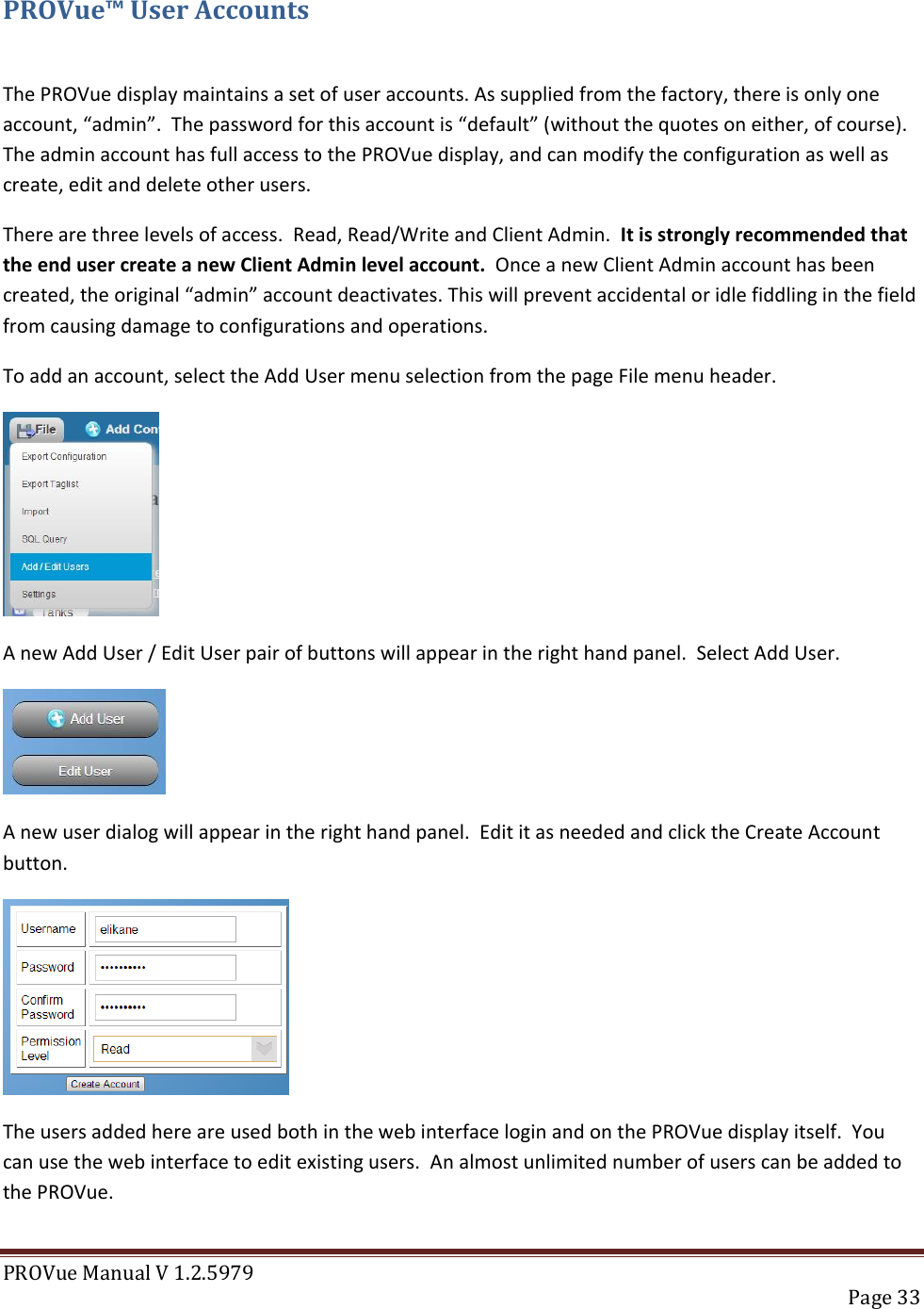
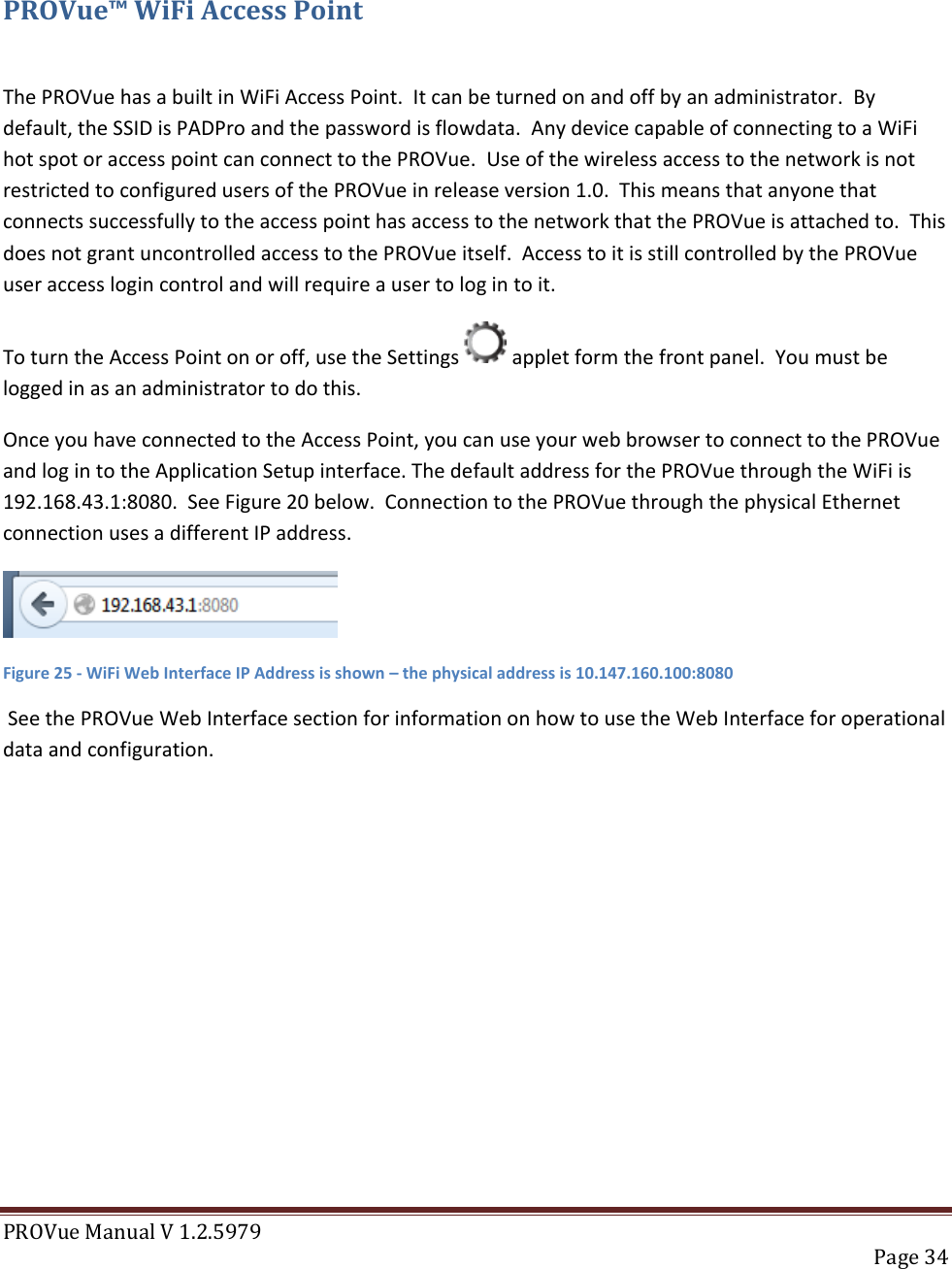
PROVUE User Manual
Users Manual
Navigation menu
Upload a User Manual
Namespaces
Wiki Guide
HTML
PDF
Info
Views
User Manual
Discussion / Help
Navigation