Furuno USA 9ZWRTR070 MARINE RADAR User Manual OPERATORS MANUAL PART4
Furuno USA Inc MARINE RADAR OPERATORS MANUAL PART4
Contents
- 1. OPERATORS MANUAL PART 1
- 2. OPERATORS MANUAL PART 2
- 3. OPERATORS MANUAL PART 3
- 4. OPERATORS MANUAL PART4
OPERATORS MANUAL PART4
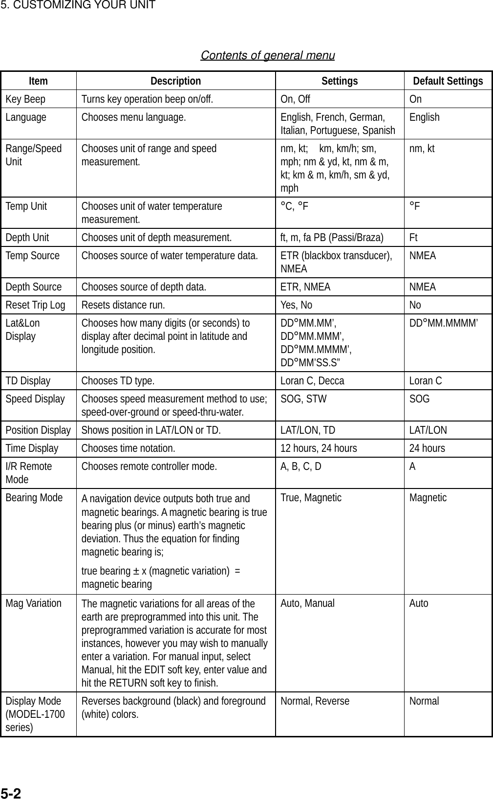
![5-15. CUSTOMIZING YOUR UNITThis chapter describes the various options which allow you to set up your unit tosuit your needs.5.1 Generic SetupThis paragraph shows you how to set up functions common to the plotter, radarand sounder displays, on the GENERAL SETUP menu, which you may displayfrom any mode. These items include data, position and time formats, units ofmeasurement, data sources, etc.1. Show the plotter display and press the [MENU] key to display the main menu.2. Press the SYSTEM CONFIGURATION soft key.3. Press the GENERAL SETUP soft key.GENERALSETUP 1RETURNNEXTPAGEEDITKEY BEEPONLANGUAGEENGLISHRANGE/SPEED UNITnm, ktTEMP UNIT°CDEPTH UNITftTEMP SOURCENMEADEPTH SOURCENMEARESET TRIP LOGNO▲Page 1 (MODEL-1700C series, MODEL-1700 series)PREV.PAGEGENERALSETUP 2EDITLAT/LON DISPLAYDD° MM.MMM'TD DISPLAYLCSPEED DISPLAYSOGPOSITION DISPLAYLAT&LONTIME DISPLAY24hoursI/R REMOTE MODEARANGE, BEARING MODERHUMB LINEBEARING MAGNETICMAG VARIATIONAUTO 7.0° W▲Page 2 (MODEL-1700C series)PREV.PAGEGENERALSETUP 2EDITLAT/LON DISPLAYDD° MM.MMM'TD DISPLAYLCSPEED DISPLAYSOGPOSITION DISPLAYLAT&LONTIME DISPLAY24hoursI/R REMOTE MODEARANGE, BEARING MODERHUMB LINEBEARING MAGNETICMAG VARIATIONAUTO 7.0° WDISPLAY MODENORMAL▲Page 2 (MODEL-1700 series)General setup menu4. Press the NEXT PAGE or PREV. PAGE soft key to switch pages if necessary.5. Use the cursor pad to select item.6. Press the EDIT soft key.7. Use the cursor pad to select option desired.8. Press the RETURN soft key.9. Press the [MENU] key to close the menu.](https://usermanual.wiki/Furuno-USA/9ZWRTR070.OPERATORS-MANUAL-PART4/User-Guide-132139-Page-1.png)
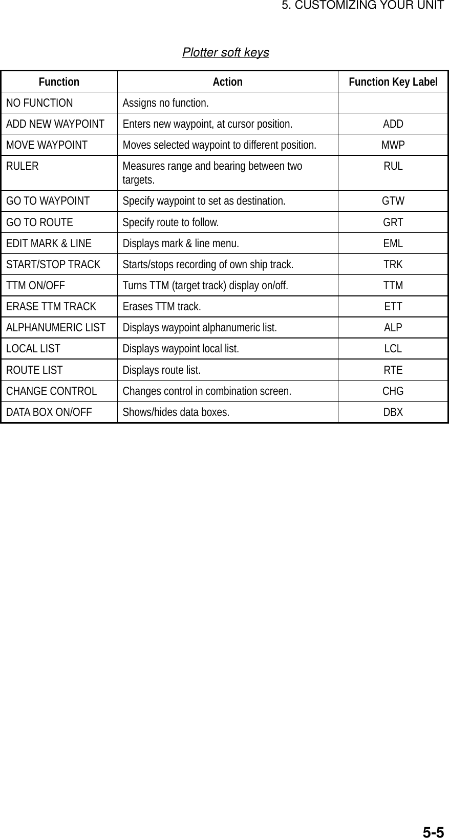
![5. CUSTOMIZING YOUR UNIT5-35.2 Plotter SetupThis paragraph provides the information necessary for setting up the plotterdisplay. Be sure to show the plotter display before executing any procedure.5.2.1 Navigation optionsNavigation options, for example, waypoint switching method, may be set on theplotter setup menu. 1. Show the plotter display and press the [MENU] key open the main menu.2. Press the PLOTTER SETUP soft key.WAYPOINT SWITCHINGAUTO 2COURSE VECTORLINESET GO TO METHOD1 POINT▲PLOTTERSETUPEDITRETURNDisplay option menuContents of display option menuItem Description Settings Default SettingWaypointsSwitching Chooses waypoint switching method. See“switching waypoints” on page 2-28. Auto 1, Auto 2,Manual AutoCourse Vector You may extend a line from the own shipposition to show ship’s course. It may be avector (length depends on ship’s speed) or asimple line (course bar)Line, Vector, Off LineSet Go toMethod Sets the method by which to navigate to aquick point. See paragraph “2.12.1 Navigatingto a quick point.”1 Point, 35 Points, 35Points & Port Service 1 Point](https://usermanual.wiki/Furuno-USA/9ZWRTR070.OPERATORS-MANUAL-PART4/User-Guide-132139-Page-3.png)
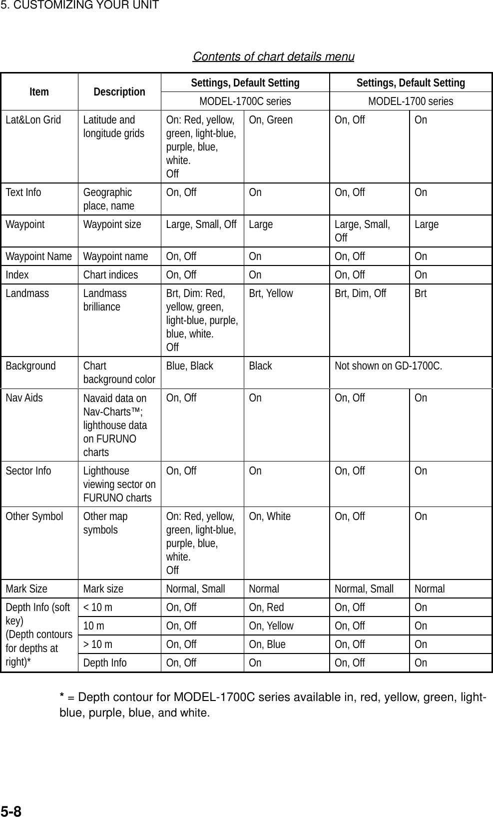
![5. CUSTOMIZING YOUR UNIT5-45.2.2 Soft key setupThe soft keys, shown when the soft keys are turned off, provide one-touch call upof a desired function.If the above settings are not to your liking you may change them as follows:1. Press the [MENU] key.2. Press the SOFT KEY SETUP soft key.FUNCKEYRETURNEDITSOFT KEY1 ADD NEW WAYPOINT A D DSOFT KEY2 MOVE WAYPOINT M W PSOFT KEY3 START/STOP TRACK T R KSOFT KEY4 ALPHANUMERIC LIST A L PSOFT KEY5 DATA BOX ON/OFF D B X▲Soft key setup menu (plotter)3. Select the function key (soft key) you want to program and press the EDIT softkey. A menu shows the functions available and the current selection ishighlighted.FUNCTIONOFFADD NEW WAYPOINTMOVE WAYPOINTRULERGO TO WAYPOINTGO TO ROUTEEDIT MARK&LINESTART/STOP TRACKTTM ON/OFFERASE TTM TRACKALPHANUMERIC LISTLOCAL LISTROUT LISTCHANGE CONTROLDATA BOX ON/OFFSoft key menu (plotter)4. Select function desired and press the ENTER soft key or the [ENTER] knob.See the table below for description of each function.5. Press the [MENU] key to close the menu.](https://usermanual.wiki/Furuno-USA/9ZWRTR070.OPERATORS-MANUAL-PART4/User-Guide-132139-Page-4.png)
![5. CUSTOMIZING YOUR UNIT5-65.3 Chart SetupThis paragraph shows you how to setup digital charts, from offsetting chartposition to turning chart attributes on or off.5.3.1 Chart offsetIn some instances position may be off by a few minutes. For example, theposition of the ship is shown to be at sea while it is in fact moored at a pier. Youcan compensate for this error by offsetting chart position as shown in theprocedure below. You can execute the procedure from any display mode.1. Show the plotter display and press the [MENU] key followed by the CHARTSETUP and CHART OFFSET soft keys. 34 24. 3456 N 359.9124 24. 3456 W 59.9kt 1+CHARTOFFSETSETOFFSETRESETOFFSETRETURNPlotter display, chart offset selected2. Use the Omnipad to place the cursor at correct latitude and longitude position.3. Press the SET OFFSET soft key.4. Press the RETURN soft key to finish.5. Press the [MENU] key to close the menu.To cancel chart offset, press the RESET OFFSET soft key at step 3 in the aboveprocedure.](https://usermanual.wiki/Furuno-USA/9ZWRTR070.OPERATORS-MANUAL-PART4/User-Guide-132139-Page-6.png)
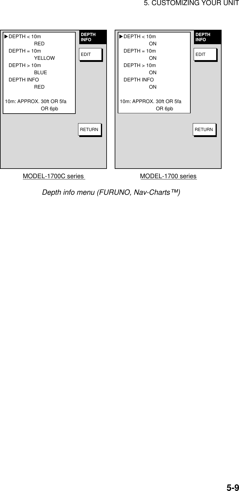
![5. CUSTOMIZING YOUR UNIT5-75.3.2 FURUNO, Nav-Charts™ chart attributesCharts attributes may be turned on or off from the chart details menu, which youmay display pressing the [MENU] key followed by the CHART SETUP andCHART DETAILS soft keys.LAT LON GRIDONTEXT INFOONWAYPOINTLARGEWAYPOINT NAMEONCHART BORDER LINESONLANDMASSONNAV AIDSONSECTOR INFOONOTHER SYMBOLONMARK SIZENORMAL▲MODEL-1700 seriesLAT LON GRIDGREENTEXT INFOONWAYPOINTLARGEWAYPOINT NAMEONCHART BORDER LINESONLANDMASSBRT YELLOWBACKGROUNDBLUENAV AIDSONSECTOR INFOONOTHER SYMBOLWHITEMARK SIZENORMAL▲MODEL-1700C seriesCHARTDETAILSEDITDEPTHINFORETURNCHARTDETAILSEDITDEPTHINFORETURNChart details menu (FURUNO, Nav-Charts™)](https://usermanual.wiki/Furuno-USA/9ZWRTR070.OPERATORS-MANUAL-PART4/User-Guide-132139-Page-7.png)
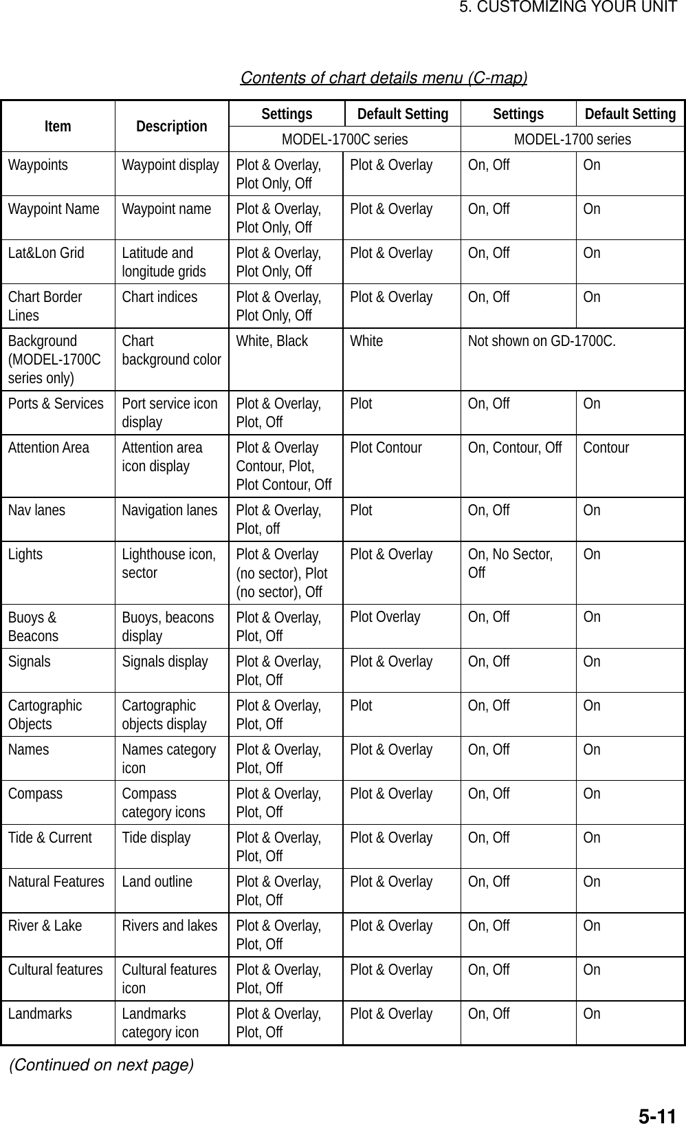
![5. CUSTOMIZING YOUR UNIT5-105.3.3 C-MAP chart attributesCharts attributes may be turned on or off from the chart details menu, which youmay display pressing the [MENU] key followed by the CHART SETUP andCHART DETAILS soft keys.▲Page 2▲Page 1CHARTDETAILSEDITDEPTHINFORETURNCHARTDETAILSEDITDEPTHINFOPREV.PAGE NAMES PLOT & OVERLAYCOMPASS PLOT & OVERLAYTIDE & CURRENTS PLOT & OVERLAYNATURAL FEATURES PLOT& OVERLAYRIVER & LAKE PLOT & OVERLAY PCULTURAL FEATURES PLOT & OVERLAYLANDMARKS PLOT & OVERLAYCHART GENERATION PLOT & OVERLAY NEW OBJECT PLOTCOMPLEX OBJECT IOCON MULTIPLEINFORMATION LEVEL DETAILEDNEXTPAGEMODEL-1700C series▲Page 2▲Page 1CHARTDETAILSEDITDEPTHINFORETURNCHARTDETAILSEDITDEPTHINFOPREV.PAGENEXTPAGE MODEL-1700 seriesWAYPOINT NAME PLOT & OVERLAY LAT/LON GRID PLOT & OVERLAY CHART BOARDER LINES PLOT & OVERLAY BACKGROUND COLOR WHITE PORTS & SERVICES PLOT ATTENTION AREAS PLOT & OVERLAY NAV LANES PLOT LIGHTS PLOT & OVERLAY BUOYS & BEACON PLOT & OVERLAY SIGNALS PLOT & OVERLAY CARTOGRAPHIC OBJECT PLOTWAYPOINTS ON NAMES PLOT & OVERLAYCOMPASS PLOT & OVERLAYTIDE & CURRENTS PLOT & OVERLAYNATURAL FEATURES PLOT& OVERLAYRIVER & LAKE PLOT & OVERLAY PCULTURAL FEATURES PLOT & OVERLAYLANDMARKS PLOT & OVERLAYCHART GENERATION PLOT & OVERLAY NEW OBJECT PLOTCOMPLEX OBJECT IOCON MULTIPLEINFORMATION LEVEL DETAILEDWAYPOINT NAME ON LAT/LON GRID ON CHART BOARDER LINES ON PORTS & SERVICES PLOT ATTENTION AREAS ON NAV LANES ON LIGHTS ON BUOYS & BEACON ON SIGNALS ON CARTOGRAPHIC OBJECT ONWAYPOINTS ONChart details menu (C-map)](https://usermanual.wiki/Furuno-USA/9ZWRTR070.OPERATORS-MANUAL-PART4/User-Guide-132139-Page-10.png)
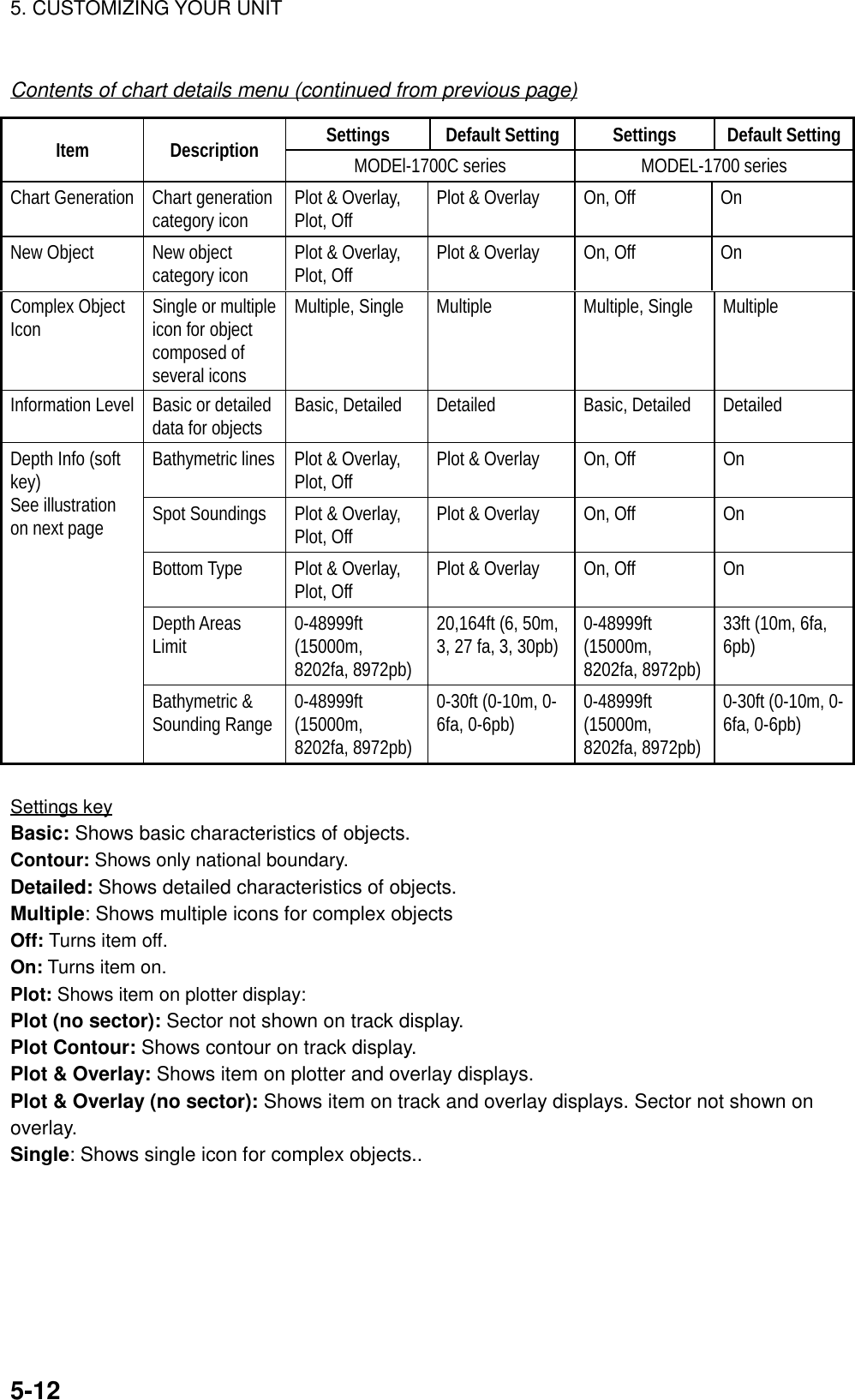
![5. CUSTOMIZING YOUR UNIT5-13▲MODEL-1700 seriesBATHYMETRIC LINESPLOTSPOT SOUNDINGSPLOT OVERLAYBOTTOM TYPEPLOT DEPTH AREAS LIMIT33ft, 66ft BATHYMETRIC & SOUNDINGS RANGE00000-00033ft▲MODEL-1700C seriesDEPTHINFOEDITRETURNDEPTHINFOEDITRETURNBATHYMETRIC LINES ONSPOT SOUNDINGSONBOTTOM TYPEON DEPTH AREAS LIMIT33ft BATHYMETRIC & SOUNDINGS RANGE00000-00033ftDepth info menu (C-map)5.4 Data Boxes SetupYou may separately select the data to show in the data boxes for the plotter, radarand sounder displays.1. Display the plotter, radar or sounder display, whichever you want to set.2. Press the [MENU] key to open the main menu.3. Press one of the following sets of soft keys depending on the display selectedat step 1.a) Plotter mode: PLOTTER OPTION, DATA BOXb) Radar mode: RADAR DISPLAY, DATA BOXc) Sounder mode: SOUNDER MENU, DATA BOX17.0 R8.2nm E1V1E2 320.1 R 359.9 R11.7nmV2 10.9nm12/3nmSPHU319. 9RTRAIL 30m02m30sG1 ING2 OUTES 2IR LNRRNG123.5 nmSPEED27.6kt TRIP LOG1022.5nmDEPTH276ft Data boxesData box menu](https://usermanual.wiki/Furuno-USA/9ZWRTR070.OPERATORS-MANUAL-PART4/User-Guide-132139-Page-13.png)
![5. CUSTOMIZING YOUR UNIT5-144. Use the Omnipad to select an item and then press the EDIT soft key.5. Select ON or OFF as desired.6. Repeat steps 3 and 4 to turn other items on or off.7. Press the RETURN soft key.8. Press the [MENU] key to close the menu.5.5 Hot Page SetupOn the full-screen selection window (see the figure at the top of the next page)five useful combination screens are preset at factory as “PAGE 1-5.” The defaultsettings arePAGE 1: Radar displayPAGE 2: Radar/plotter displayPAGE 3: Plotter/sounder displayPAGE 4: Plotter/compass displayPAGE 5: Plotter/highway displayIf the default settings are not to your liking you may change them as follows:1. Press the [MENU] key followed by pressing the SYSTEM CONFIGURATION,HOT PAGE & NAV DISPLAY and HOT PAGE SETUP soft keys in that order.HOT PAGE 1HOT PAGE 2HOT PAGE 3HOT PAGE 4HOT PAGE 5 EDITRETURNH-PAGESETUPPAGE 1 PAGE 2 PAGE 3PAGE 4 PAGE 5Hot page menu2. Use the cursor pad to select the hot page number to set and then press theEDIT soft key. The full-screen selection window appears.](https://usermanual.wiki/Furuno-USA/9ZWRTR070.OPERATORS-MANUAL-PART4/User-Guide-132139-Page-14.png)
![5. CUSTOMIZING YOUR UNIT5-15PAGE 1 PAGE 2 PAGE 3 PAGE 4 PAGE 5RADAR PLOT SNDR NAV OVRLY· TURN KNOB TO SELECT MODE AND PUSH TO SET.· PUSH ANY SOFTKEY TO SELECT IMAGE SOURCE.Basic displayscreensPreset combinationscreen displaysFull-screen selection window3. Rotate the [ENTER] knob to select the basic mode desired and press the[ENTER] knob. The combination screen selection window appears.RADAR PLOT SNDR NAVOVRLYPUSH ENTER KNOB.Combination screen selection window4. Rotate the [ENTER] knob to select the combination mode and push it to set.](https://usermanual.wiki/Furuno-USA/9ZWRTR070.OPERATORS-MANUAL-PART4/User-Guide-132139-Page-15.png)
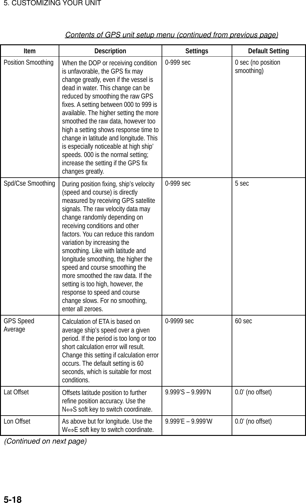
![5. CUSTOMIZING YOUR UNIT5-165.6 Navigator SetupIn this section you will learn how to set up the position-fixing equipmentconnected to your unit.5.6.1 Navigation data sourceThe nav source menu mainly selects the source of nav data and smooths positionand speed. Press the [MENU] key followed by the SYSTEM CONFIGURATION,NAV OPTIONS and NAV SOURCE soft keys to display this menu.NAVOPTIONRETURN+ -EDITPOSTION SOURCEFURUNO GPS SENSORSPEED AVERAGE*60sLOCAL TIME OFFSET*-11h00m▲* Non-blackbox navigator only.Nav source menuContents of nav source menuItem Description Settings DefaultSettingPositionSource Chooses source of position data. FURUNO GPS Sensor:Blackbox GPS unitGP: GPS navigator ( via F. NETor NMEA connector)LC: Loran C ( via F. NET orNMEA connector)All: Multiple navaid connection( via F. NET or NMEAconnector)AllSpeedAverage Calculation of ETA is based on average ship’s speedover a given period. If the period is too long or tooshort calculation error will result. Change this settingif calculation error occurs. The default setting is 60seconds, which is suitable for most conditions.0-9999 sec 60 secLocalTimeOffsetGPS uses UTC time. If you would rather use localtime enter the time difference between it and UTC.Use the +⇔- soft key to switch from plus to minusand vice versa.-13:30 to +13:30 0](https://usermanual.wiki/Furuno-USA/9ZWRTR070.OPERATORS-MANUAL-PART4/User-Guide-132139-Page-16.png)
![5. CUSTOMIZING YOUR UNIT5-175.6.2 Blackbox GPS unit setupThe GPS unit setup menu sets up the blackbox GPS unit. Press the [MENU] keyfollowed by the SYSTEM CONFIGURATION, NAV OPTIONS and GPS UNITSETUP soft keys to display this menu.GPSSETUPRETURNGPSMON.EDITLOCAL TIME OFFSET+00h30mGEODETIC DATUMWGS-84POS SMOOTHING00SPD/CSE SMOOTHING05GPS SPD AVERAGE60sLAT OFFSET0.000'LON OFFSET0.000'DISABLE SAT_ _ _LATITUDE 34° 12.345' NLONGITUDE135° 12.345' EFIX MODE 2D/3DANT. HEIGHT5mCOLD STARTNO▲N SE WGPS unit setup menuContents of GPS unit setup menuItem Description Settings Default SettingLocal Time Offset Allows the user to use local time(instead of UTC time). Enter timedifference between local time andUTC time.-13:30 to +13:30 hr 0hrGeodetic Datum Your equipment is preprogrammedwith most of the major chart systemsof the world. Although the WGS-84system, the GPS standard, is nowwidely used other categories ofcharts still exist. Select the chartsystem used, not the area where yourboat is sailing. The default chartsystem is WGS-84.See Appendix for full list. WGS-84(Continued on next page)](https://usermanual.wiki/Furuno-USA/9ZWRTR070.OPERATORS-MANUAL-PART4/User-Guide-132139-Page-17.png)
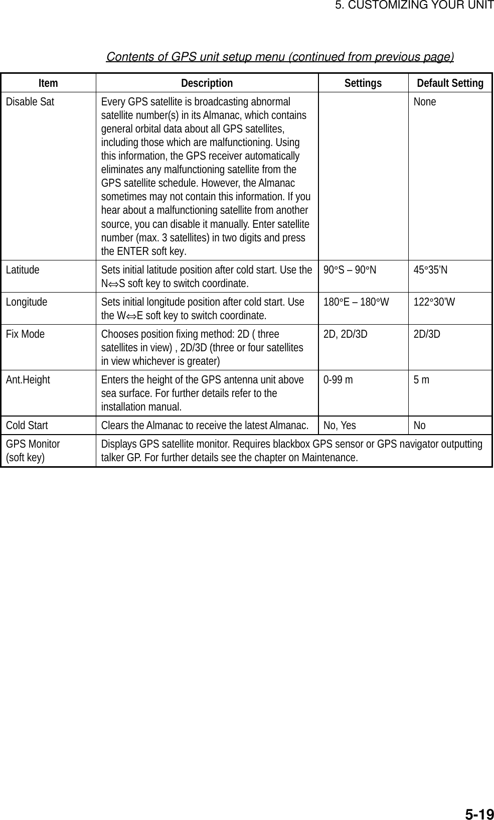
![5. CUSTOMIZING YOUR UNIT5-205.6.3 TD display setupThe TD option menu sets which Loran C or Decca chain to use. Press the[MENU] key followed by the NAV OPTIONS and TD OPTION soft keys to displaythis menu.TDOPTIONRETURNNEXTPAGEGPSMON.+⇔-EDITLORAN CGRI9970:30-55N.PACIFICCORRECTION 1+0000.0 µsCORRECTION 2+0000.0 µs DECCACHAIN31:R-GHOKKAIDOCORRECTION 1+00.00 LANECORRECTION 2+00.00 LANE▲TD option menuDisplaying Loran C TDs1. Select GRI and press the EDIT soft key to show the GRI & sta. pair window.GRI & STA. PAIRUS W COAST9940 11-27▲▼▼Loran GRI & station pair window2. Select GRI code. Press to enable selection of station pair, and then selectstation pair. See the Loran C chain list at the end of this manual for GRI andstation pairs.3. Press the ENTER soft key to register your selection.4. If necessary, you may enter a position offset to refine Loran C positionaccuracy. Select LORAN C CORRECTION1 or CORRECTION2 and pressthe EDIT soft key. Enter correction value and press the ENTER soft key. Usethe +⇔- soft key to switch from plus to minus and vice versa.5. Press the RETURN soft key.6. Press the [MENU] key to close the menu.7. Press the [MENU] key again followed by the SYSTEM CONFIGURATION andGENERAL SETUP soft keys.8. Select “Loran C” from “TD Display.”9. Press the [MENU] key to close the menu.](https://usermanual.wiki/Furuno-USA/9ZWRTR070.OPERATORS-MANUAL-PART4/User-Guide-132139-Page-20.png)
![5. CUSTOMIZING YOUR UNIT5-21Displaying DECCA TDs1. Select DEC CHAIN and press the EDIT soft key to show the chain sta. pairwindow.CHAIN & STA. PAIRSOUTH BALTIC01 R-P▲▼▼Decca chain and station pair window2. Select Decca chain number. Press to enable selection of lane, and thenselect lane pair (R: red, G: green and P: purple). Refer to the Decca chain listat the end of this manual.3. Press the ENTER soft key to register your selection.4. If necessary, you may enter position offset to refine Decca position. SelectDECCA CORRECTION1 or CORRECTION2 and press the EDIT soft key.Enter correction value and press the ENTER soft key. Use the +⇔ - soft keyto switch from plus to minus and vice versa.5. Press the RETURN soft key.6. Press the [MENU] key to close the menu.7. Press the [MENU] key again followed by the SYSTEM CONFIGURATIONand GENERAL SETUP soft keys.8. Select “Decca” from “TD Display.”9. Press the [MENU] key to close the menu.](https://usermanual.wiki/Furuno-USA/9ZWRTR070.OPERATORS-MANUAL-PART4/User-Guide-132139-Page-21.png)
![5. CUSTOMIZING YOUR UNIT5-225.7 Nav Data Display SetupThe nav data display provides various navigation data. You may select the datato display and where to display it, on the monitor setup menu.1. Press the [MENU] key to open the main menu.2. Press the PLOTTER MENU, SYSTEM CONFIGURATION, HOT PaGE & NAVDISPLAY, NAV DATA DISPLAY SETUP soft keys.1POSITION2SPEED 3CSE4RNG 5BRG6DEPTH 7TEMP8LOG TRIP 9LOG TRIP10SPEED 11CSE12POSITION13RNG 14BRGMONITORSETUPEDITRETURNPositionsfor fullscreenPositionsfor halfscreenNav data display setup menu3. Use the Omnipad to select a position. Positions 1-9 are for the full-screen navdata display and positions 10-14 for the half-screen nav data display.4. Press the EDIT soft key. The following display appears.1POSITION2SPEED 3CSE4RNG 5BRG6DEPTH 7TEMP8LOG TRIP 9LOG TRIP10SPEED 11CSE12POSITION13RNG 14BRGPOSITIONWPT POSITIONSOGSTWCOURSEBEARINGRANGEDEPTHTEMPLOG TRIPTTGETADATETIMEDISPLAY DATANAV DATASETUPRETURNENTERDisplay data window](https://usermanual.wiki/Furuno-USA/9ZWRTR070.OPERATORS-MANUAL-PART4/User-Guide-132139-Page-22.png)
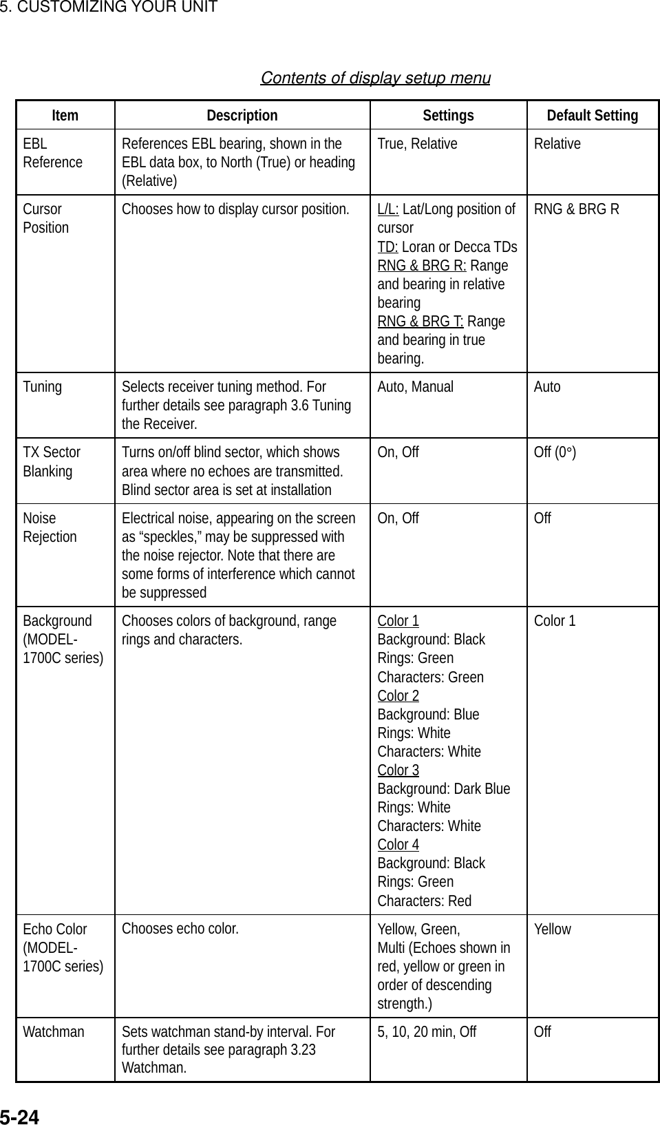
![5. CUSTOMIZING YOUR UNIT5-235. Select the data to display and press the ENTER soft key.6. Repeat steps 4-6 to set other locations.7. Press the [MENU] key to finish.5.8 Radar SetupThis paragraph explains how to customize the radar display to suit youroperational needs. Be sure to show the radar display before executing any of theprocedures.5.8.1 Radar display setupThe radar display may be set up from the display setting menu, which containsitems such as EBL reference and cursor position format.1. Press the [MENU] key to show the main menu.2. Press the RADAR MENU soft key.3. Press the DISPLAY SETUP soft key to show the display setup menu.EBL REFERENCERELATIVECURSOR POSITIONRNG & BRG TTUNINGAUTOTX SECTOR BLANKINGOFFNOISE REJECTIONONBACKGROUND COLORBLACKECHO COLORYELLOWWATCHMANOFF▲DISPLAYSETTINGEDITDATABOXEBL REFERENCERELATIVECURSOR POSITIONRNG & BRG TTUNINGAUTOTX SECTOR BLANKINGOFFNOISE REJECTIONONWATCHMANOFF▲DISPLAYSETTINGEDITRETURNMODEL-1700C series MODEL-1700 seriesRETURNDATABOXDisplay setup menu](https://usermanual.wiki/Furuno-USA/9ZWRTR070.OPERATORS-MANUAL-PART4/User-Guide-132139-Page-23.png)
![5. CUSTOMIZING YOUR UNIT5-255.8.2 Radar range setupThe radar has 16 (km) and 17 (nm) ranges, some of which you may not require.You may turn off ranges you do not require, from the range setup menu. Afterchoosing the ranges desired change the range to activate range settings.Note that at least two ranges (excluding maximum range) must be turned on.When less than two ranges are turned on a buzzer sounds.1. Press the [MENU] key to show the main menu.2. Press the RANGE SETUP soft key to show the range setup menu.RANGESETUPRETURNON/OFF0.125nm0.25nm0.5nm0.75nm1nm1.5nm2nm3nm4nm6nm8nm12nm16nm24nm36nm48nm64nmMAX RANGE 64nmONONONONONONONONONONONONONONONONON▲Range unit: nmRANGESETUPRETURNON/OFF0.25km0.5km0.75km1km1.5km2km3km4km6km8km12km16km24km36km48km64kmMAX RANGE 64kmONONONONONONONONONONONONONONONON▲Range unit: kmRange setup menu3. Use the Omnipad to select the range which you want to turn on or off.4. Press the ON/OFF soft key to turn the range on or off as appropriate.5. Press the RETURN soft key.6. Press the [MENU] key to close the menu.](https://usermanual.wiki/Furuno-USA/9ZWRTR070.OPERATORS-MANUAL-PART4/User-Guide-132139-Page-25.png)
![5. CUSTOMIZING YOUR UNIT5-265.8.3 Function key setupThe function keys, shown when the soft keys are turned off, provide one-touchcall up of a desired function. The default radar function key settings are#1 function key: Gain#2 function key: A/C SEA#3 function key: Data box#4 function key: Range rings#5 function key: Change controlIf the above settings are not to your liking you may change them as follows:1. Show the radar display.2. Press the [MENU] key.3. Press the FUNCTION KEY SETUP soft key.FUNCKEYRETURNEDITSOFT KEY1 GAIN G A ISOFT KEY2 A/C SEA S E ASOFT KEY3 DATA BOX ON/OFF D B XSOFT KEY4 RINGS R N GSOFT KEY5 CHANGE CONTROL C N T▲Function key menu (radar)4. Select the function key you want to program and press the EDIT soft key. Usethe cursor pad to scroll the screen if necessary.▲FUNCTIONOFFHEADING LINE OFFMODEGAIN SENSITIVITYA/C SEAA/C RAINFTCECHO STRETCHPULS LENGTHZOOMOFFCENTERTRAILRINGSFunction menu (radar)](https://usermanual.wiki/Furuno-USA/9ZWRTR070.OPERATORS-MANUAL-PART4/User-Guide-132139-Page-26.png)
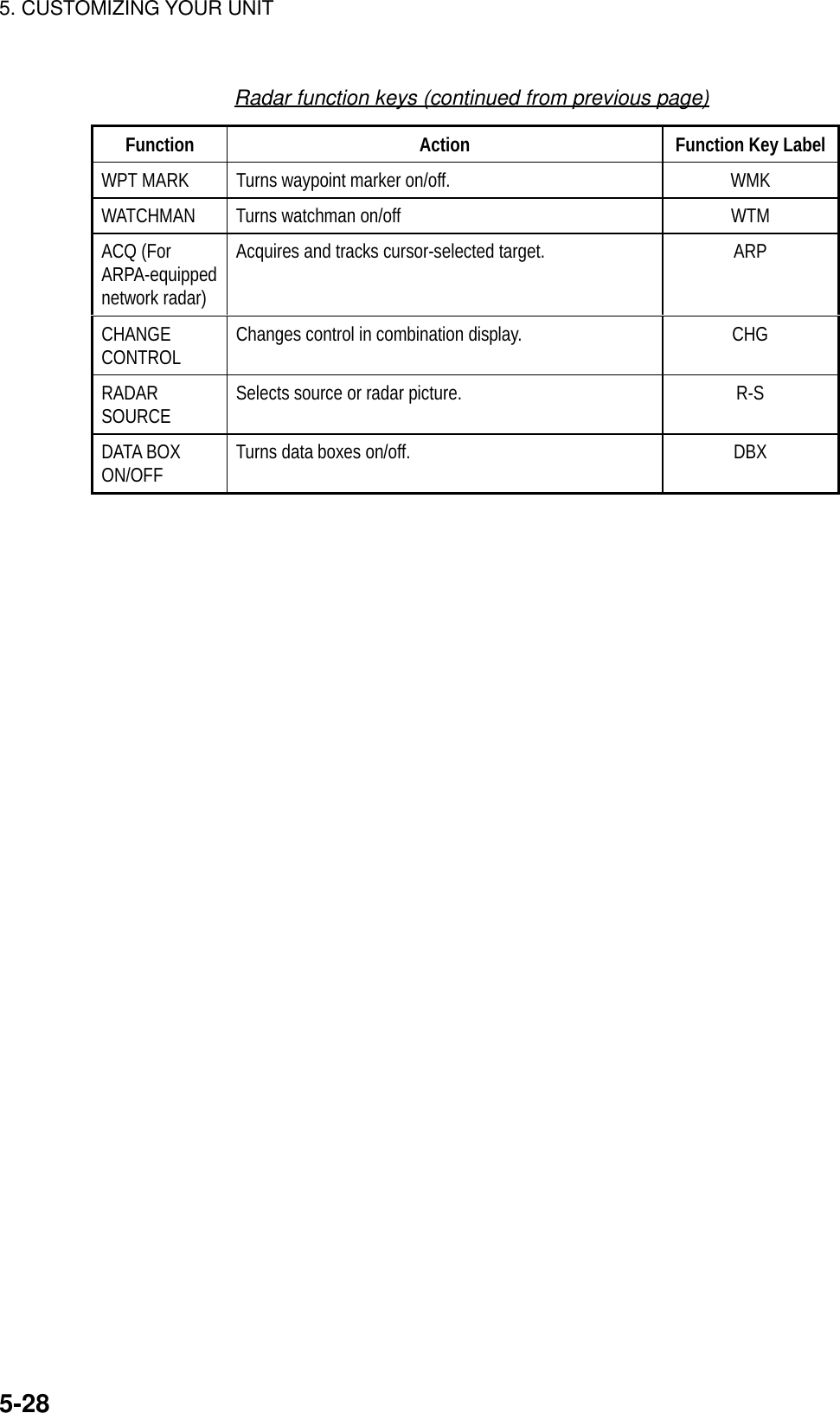
![5. CUSTOMIZING YOUR UNIT5-275. Select function desired and press the RETURN soft key. See the table on thenext page for details.6. Press the [MENU] key to close the menu.Radar functions keysFunction Action Function KeyLabelNO FUNCTION Assigns no function.HEADING LINE Turns heading line on/off. HLMODE Selects presentation mode. MODGAIN SENSITIVTY Shows manual or automatic gain window depending oncurrent gain mode. GAIA/C SEA Shows manual or automatic A/C SEA window dependingon current A/C SEA mode. SEAA/C RAIN Shows manual or automatic A/C RAIN window dependingon current A/C RAIN mode. RAIFTC Displays FTC window. Adjust FTC with the [ENTER]knob. FTCECHO STRETCH Turns echo stretch on/off. ESPULSE LENGTH Sets pulselength (long or short). PLSZOOM Touch-and-release to double size of cursor-selectedtarget, in zoom window. Press again to fix cursor. Pressand hold down to turn zoom off.ZOMOFFCENTER Press to shift display center to cursor location. Pressagain to turn shift off and return cursor to display center. SFTTRAIL Starts/stops target trails. TRLRINGS Turns range rings on/off. RNGTLL Outputs cursor position, in NMEA format, to navigator. TLLALM Displays alarm soft keys. ALMEBL Displays EBL if it is off; enables control of EBL if its active. EBLVRM Displays VRM if it is off; enables control of VRM if itsactive. VRMTTM Turns TTM data on/off. Place cursor on TTM target tofinds its data. Press and hold down to turn off TTM targetand its data.TTM(Continued on next page)](https://usermanual.wiki/Furuno-USA/9ZWRTR070.OPERATORS-MANUAL-PART4/User-Guide-132139-Page-27.png)
![5. CUSTOMIZING YOUR UNIT5-295.9 Sounder SetupThis section shows you how to customize your sounder to your liking. You can setfish alarm sensitivity, fine tune sensors, etc.5.9.1 System setup1. Show the sounder display and press the [MENU] key.2. Press the SYSTEM SETUP soft key.SOUNDERSETUPRETURNSENSORSETUPEDITFISH ALARM LEVEL0TXONTVG 200kHz5TVG 50kHz5ECHO OFFSET 200kHz0ECHO OFFSET 50kHz0SEABED LEVEL 200kHz80SEABED LEVEL 50kHz80KP PULSEINTERNALSMOOTHINGNORMAL▲Sounder setup menuSystem setup menu descriptionItem Description Settings Default SettingFish Alm Lvl Sets the fish alarm sensitivity; whichecho strength will trigger the alarm. High: only thestrongest echoestrigger the alarm.Normal: Echoesfrom strong tomedium strengthtrigger the alarm.Low: Any echotriggers thealarm.NormalTX Turns TX power on/off. The defaultsetting is ON. On, Off On](https://usermanual.wiki/Furuno-USA/9ZWRTR070.OPERATORS-MANUAL-PART4/User-Guide-132139-Page-29.png)
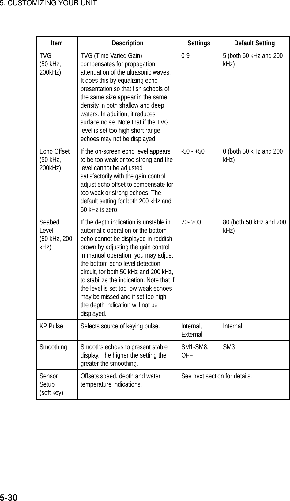
![5. CUSTOMIZING YOUR UNIT5-315.9.2 Sensor setupThe sensor setup menu lets you compensate for speed, temperature and deptherror in the sensor(s) connected to the blackbox sounder.1. Show the sounder display and press the SENSOR SETUP soft key at thesystem setup menu to show the sensor setup menu. The current readout forspeed, water temperature, depth and sonic speed are shown at the bottom ofthe menu.ES SENSSETUPRETURNEDITSPEED ADJUST+ 0%TEMP. ADJUST+ 0°FDEPTH ADJUST+12ftSONIC SPEED ADJUST+ 200m/s▲SPEED12.3ktDEPTH125ftTEMPERATURE78°FSONIC SPEED1700m/sSensor setup menu2. Select item to adjust and press the EDIT soft key.3. Display appropriate value as below.Speed and temperature: Enter appropriate percentage. For example, if thewater temperature readout is 77°F but the actual water temperature is 75.4°F,enter –2(%).Depth: Enter plus or minus value. For example, if the depth readout is 125 ftbut the actual depth is 126 ft, enter +1(ft).Sonic speed adjustment: Sets the speed of sound used by the blackboxsensor. Normally no adjustment is required, however if echoes are returningtoo slow or too fast adjust the value as appropriate.Sensor setup menu settingsItem Settings Default SettingSpeed Adjust -50 -+50% 0% (no offset)Temp Adjust -20 -+20°C, -40 - +40°F 0% (no offset)Depth Adjust -10 - +40 m; -30 – 130 ft;-6 - +25 fa, -6 – 25 pb0 ft, m, fa, pb(no offset)Sonic SpeedAdjust-500 - +500 m/s 0 m/s (no offset)4. Press the RETURN soft key followed by the [MENU] key.](https://usermanual.wiki/Furuno-USA/9ZWRTR070.OPERATORS-MANUAL-PART4/User-Guide-132139-Page-31.png)
![5. CUSTOMIZING YOUR UNIT5-325.9.3 Sounding range, zoom range, bottom lock rangeThis paragraph shows you how to set custom ranges and choose zoom andbottom lock ranges.1. Show the sounder display and press the [MENU] key to open the main menu.2. Press the SOUNDER RANGE SETUP soft key to show the sounder rangemenu.SOUNDERSETUPRETURNEDITRANGE 15 mRANGE 210 mRANGE 320 mRANGE 440 mRANGE 580 mRANGE 6150 mRANGE 7300 mRANGE 81200 mZOOM RANGE20 mB/L RANGE3 m▲Sounder range menu3. Select the range to change and press the EDIT soft key. For the zoom rangethe available settings are as below.4. Use the cursor pad to set range desired.5. Press the RETURN soft key.6. Press the [MENU] key to finish.Default rangesRange 1 Range 2 Range 3 Range 4 Range 5 Range 6 Range 7 Range 85 m 10 m 20 m 40 m 80 m 150 m 300 m 1200 m15 ft 30 ft 60 ft 120 ft 200 ft 400 ft 1000 ft 4000 ft3 fa 5 fa 10 fa 20 fa 40 fa 80 fa 150 fa 650 fa3 pb 6 pb 12 pb 24 pb 50 pb 100 pb 200 pb 700 pbSetting range: 2 m –1200m, 7 ft – 4000 ft, 1 fa – 650 fa, 1 pb – 700 pbZoom range, Bottom lock rangeItem Settings Default SettingZoom Range 2 m – 1200 m, 7 ft – 4000 ft,1 fa – 650 fa, 1 pb – 700 pb10 m, 30 ft, 10 fa, 10 pbB/L Range 3 m, 10 ft, 2 fa, 2 pb6 m, 20 ft, 3 fa, 3 pb6 m, 20 ft, 3 fa, 3pb](https://usermanual.wiki/Furuno-USA/9ZWRTR070.OPERATORS-MANUAL-PART4/User-Guide-132139-Page-32.png)
![5. CUSTOMIZING YOUR UNIT5-335.9.4 Function key setupThe function keys, shown when the soft keys are turned off, provide one-touchcall up of a desired function. The default sounder function key settings are#1 function key : Auto mode#2 function key: Gain 200 kHz#3 function key: Clutter#4 function key: Picture advance#5 function key: HueIf the above settings are not to your liking you may change them as follows:1. Show the sounder display.2. Press the [MENU] key.3. Press the FUNCTION KEY SETUP soft key.FUNCKEYRETURNEDITSOFT KEY1 AUTO MODE M O DSOFT KEY2 GAIN 200 G 2 0SOFT KEY3 CLUTTER C L TSOFT KEY4 PIC. ACV P ASOFT KEY5 HUE H U E▲Function key menu (radar)4. Select the function key you want to program and press the EDIT soft key. Amenu shows the functions available.▲FUNCTIONOFF AUTO MODEGAIN 200GAIN 50SHIFTN. LEVELCLUTTERW.MAKERHUESUG.LEVELCHANGE CONTROLPIC.ADVTEMP.GRPFunction menu (sounder)](https://usermanual.wiki/Furuno-USA/9ZWRTR070.OPERATORS-MANUAL-PART4/User-Guide-132139-Page-33.png)
![5. CUSTOMIZING YOUR UNIT5-345. Select function desired and press the RETURN soft key. See the table on thenext page for details.6. Press the [MENU] key to close the menu.Sounder functions keysFunction Action Function Key LabelMODE Automatic sounder mode. MODGAIN 200 kHz Adjusts gain for 200 kHz. G20GAIN 50 kHz Adjusts gain for 50 kHz. G 5SHIFT Shifts range in manual operation. SFTNOISE LEVEL Suppresses noise. NLVCLUTTER Suppresses clutter. CLTWHITE MARKER Sets white marker. WMKHUE (GD-1700C) Sets hue. HUESIGNAL LEVEL(GD-1700C) Erases weak signals. SLVPICTURE ADVANCE Sets picture advance speed. P ATEMP GRAPHON/OFF Turns temperature graph on/off. T GTVG 200 Sets TVG for 200 kHz. TV2TVG 50 Sets TVG for 50 kHz. TV5ECHO OFFSET 200 Offsets echo strength for 200 kHz. EO2ECHO OFFSET 50 Offsets echo strength for 500 kHz. EO5SMOOTHING Sets smoothing rate. SMZZOOM RANGE Sets zoom range for marker zoom display. ZMRB/L RANGE Sets bottom lock range for bottom lock display. BLRCHANGE CONTROL Changes control in combination display. CHGTLL Outputs current position in NMEA format. Alsoinscribes line on sounder and registers positionas a waypoint.TLLDATA BOX ON/OFF Turns data boxes on/off. DBXNO FUNCTION Assigns no function.](https://usermanual.wiki/Furuno-USA/9ZWRTR070.OPERATORS-MANUAL-PART4/User-Guide-132139-Page-34.png)
![5. CUSTOMIZING YOUR UNIT5-355.10 Data Port SetupThe display unit has four ports on its rear panel for connection of externalequipment: GPS/NMEA port, GPS port, PC/NMEA/EXT BUZZ port and NavNetport. Set up these ports according to the equipment connected to them. TheGPS/NMEA, GPS, and PC/NMEA/EXT BUZZ ports are set up on the port setupmenu. For the NavNet port see the installation menu.5.10.1 GPS/NMEA port (MODEL-1700 series only)The navigator connected to the GPS/NMEA port can be set up on theGPS/NMEA port menu.1. Press the [MENU] key to open the main menu.2. Press the SYSTEM CONFIGURATION, SYSTEM SETUP, PORT SETUP andGPS/NMEA soft keys to show the GPS/NMEA menu.GENERALSETUP 1RETURNNEXTPAGEEDITKEY BEEPONLANGUAGEENGLISHRANGE/SPEED UNITnm, ktTEMP UNIT°CDEPTH UNITftTEMP SOURCENMEADEPTH SOURCENMEARESET TRIP LOGNO▲Page 1 (MODEL-1700C series, MODEL-1700 series)PREV.PAGEGENERALSETUP 2EDITLAT/LON DISPLAYDD° MM.MMM'TD DISPLAYLCSPEED DISPLAYSOGPOSITION DISPLAYLAT&LONTIME DISPLAY24hoursI/R REMOTE MODEARANGE, BEARING MODERHUMB LINEBEARING MAGNETICMAG VARIATIONAUTO 7.0° W▲Page 2 (MODEL-1700C series)PREV.PAGEGENERALSETUP 2EDITLAT/LON DISPLAYDD° MM.MMM'TD DISPLAYLCSPEED DISPLAYSOGPOSITION DISPLAYLAT&LONTIME DISPLAY24hoursI/R REMOTE MODEARANGE, BEARING MODERHUMB LINEBEARING MAGNETICMAG VARIATIONAUTO 7.0° WDISPLAY MODENORMAL▲Page 2 (MODEL-1700 series)GPS/NMEA port menu](https://usermanual.wiki/Furuno-USA/9ZWRTR070.OPERATORS-MANUAL-PART4/User-Guide-132139-Page-35.png)
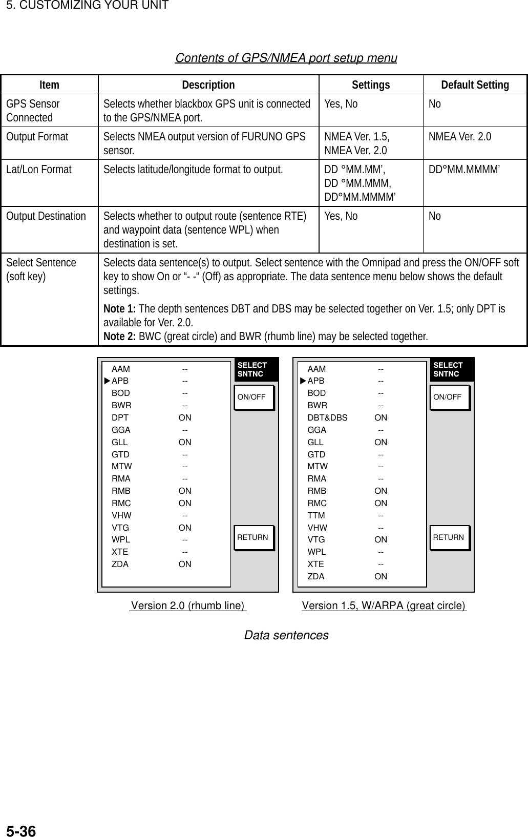
![5. CUSTOMIZING YOUR UNIT5-375.10.2 NMEA PORT menuThe NMEA port setup menu sets up the equipment connected to the NMEA port.The contents of the menu are similar to that of the GPS/NMEA PORT menu. Youcan display this menu by pressing the [MENU] key followed by the SYSTEMCONFIGURATION, SYSTEM SETUP, PORT SETUP AND GPS/NMEA soft keys.5.10.3 PC/NMEA/EXT BUZZ. PORT menuThe PC/NMEA ext buzz port menu sets up of the equipment connected to thePC/NMEA EXT BUZZ port.1. Press the [MENU] key to open the main menu.2. Press the CONFIGURATION, SYSTEM SETUP, PORT SETUP ANDGPS/NMEA soft keys to show the PC/NMEA/EXT BUZZ menu.NMEAPORTRETURNSELECTSNTNCEDITNMEA OUTPUT FORMAT NMEA 0183 VER2.0BAUD RATE4800bpsBIT LENGTH8bitSTOP BIT1bitPARITY NONE(CONTROL: Xon/Xoff)▲ WIRE INFO.TxD-H >1>---WHITERxD-C >2>---BLACKRD-H >3>---YELLOWRD-H >4>---GREEN+12V >5>---REDEXT BUZZ >6>---BLUEGND >7>---SHIELDPC/NMEA/EXT BUZZ PORT menuContents of PC/NMEA/EXT BUZZ PORT menuItem Description Settings Default SettingNMEAOutputFormatSelectsNMEA output format NMEA Ver. 1.5,NMEA Ver. 2.0 NMEA Ver. 2.0Baud Rate Sets baud rate of equipmentconnected to this port. 4800, 9600, 19200,38400, 57600(bps) 4800(bps)Bit Length Sets character length. 8 bit, 7 bit 8 bitStop Bit Sets number of stop bits. 1 bit, 2 bit 1 bitParity Sets parity bit. Even, Odd, None NoneSelectSntnc (softkey)Sets Ver 2.0 sentences to output. For further details see the illustration andand table on page 5-36.](https://usermanual.wiki/Furuno-USA/9ZWRTR070.OPERATORS-MANUAL-PART4/User-Guide-132139-Page-37.png)
![6. DATA TRANSFER6-16. DATA TRANSFERThis chapter provides information for saving and replaying memory cards, anduploading and downloading data.6.1 Memory Card OperationsThe memory cards function to store data, and the following data can be saved:• Marks/lines• Waypoints/routes• Track• Configuration (menu settings)6.1.1 Formatting memory cardsBefore you can use a memory card it must be formatted. This prepares the cardfor use with the system. Note that formatting a used card erases all saved data.1. Insert the memory card you want to format into the card slot.2. Press the [MENU] key followed by the SYSTEM CONFIGURATION, DATATRANSFER, UPLOAD/DOWNLOAD DATA and SAVE DATA TO MEMORYCARD soft keys to show the save data menu.TRACKOFFWAYPOINT & ROUTESOFFMARK/LINEOFFSETTING DATAOFF▲SAVEDATAEDITSAVEFORMATRETURNSave data menu3. Press the FORMAT soft key. You are asked if you are ready to format thememory card.4. Push the [ENTER] knob to format (or press the [CLEAR] key to escape).“NOW FORMATTING MEMORY CARD” appears. Do not remove the cardwhile it is being formatting. When the formatting is completed, “FORMATCOMPLETED” appears.5. Push the [ENTER] knob to finish.](https://usermanual.wiki/Furuno-USA/9ZWRTR070.OPERATORS-MANUAL-PART4/User-Guide-132139-Page-38.png)
![6. DATA TRANSFER6-26.1.2 Saving data to a memory card1. Insert a formatted memory card into the slot.2. Press the [MENU] key followed by the CONFIGURATION, DATA TRANSFER,UPLOAD/DOWNLOAD DATA and SAVE DATA TO MEMORY CARD softkeys to show the SAVE DATA display.TRACKOFFWAYPOINT & ROUTESOFFMARK/LINEOFFSETTING DATAOFF▲LOADDATAEDITLOADRETURNLoad data menu3. Select item to save.4. Press the EDIT soft key.5. Select ON.6. Press the ENTER soft key.7. Repeat from steps 4 to 7 to save other data if desired.8. Press the SAVE DATA soft key. The message “NOW SAVING DATA TOMEMORY CARD. DO NOT TURN OFF THE POWER UNTIL SAVING ISCOMPLETED.” appears.When saving is completed, COMPLETE SAVING DATA appears. Press the[ENTER] knob.](https://usermanual.wiki/Furuno-USA/9ZWRTR070.OPERATORS-MANUAL-PART4/User-Guide-132139-Page-39.png)
![6. DATA TRANSFER6-3Error messagesVarious error messages appear to alert you to memory card-related error. Theseare tabulated below.Error messagesError Message Reason RemedyMemory card notinserted. Insert card.Press “ENTER” key tocontinue.Memory card notinserted.Push the [ENTER] knob to return to theSAVE DATA display.Memory card notformatted. Press“ENTER” key tocontinue.Unformatted memorycard.Push the [ENTER] knob to return to theSAVE DATA display. Format the cardreferring to the previous page.Wrong card inserted.Insert memory card.Press “ENTER” key tocontinue.Chart card insertedinstead of memorycard.Insert memory card.Overwrite followingdata OK?(Track)Data type to berecorded exists onmemory card. (Twoor more of same typeof data cannot berecorded.)Push the rotary encoder key to overwritesame data type on the card, or press the[CLEAR] key to escape.](https://usermanual.wiki/Furuno-USA/9ZWRTR070.OPERATORS-MANUAL-PART4/User-Guide-132139-Page-40.png)
![6. DATA TRANSFER6-46.1.3 Playing back from a memory cardData (track, marks, waypoints, configuration) can be loaded from a memory cardand displayed on the screen. This feature is useful for observing past data andsetting up the equipment for a specific purpose (with “configuration”).1. Press the [MENU] key followed by the SYSTEM CONFIGURATION andDATA TRANSFER soft keys.2. Press the UPLOAD/DOWNLOAD DATA soft key.3. Press the LOAD DATA FROM MEMORY CARD soft key to show the LOADDATA menu.TRACKOFFWAYPOINT & ROUTESOFFMARK/LINEOFFSETTING DATAOFF▲LOADDATAEDITLOADRETURNLoad data menu4. Select item to load.5. Press the EDIT soft key.6. Select ON. Press the ENTER soft key or the [ENTER] knob. If the memorycard does not contain the item selected, the buzzer sounds and ON cannot beselected.7. After you select all items desired, press the LOAD DATA soft key to load data.The message “NOW LOADING DATA FROM MEMORY CARD. DO NOTTURN OFF THE POWER UNTIL SAVING IS COMPLETED.” appears.8. After loading is completed, push the [ENTER] knob to finish.Notes on loading dataTrack: Since loaded track data is added to internal track, oldest track will beentered when the track memory capacity is exceeded.Waypoint/route: The loaded data substitutes for previously stored.Mark/line: The loaded data is added to internal data. When the mark/linememory becomes full no marks may be entered.Configuration: The loaded data replaces current configuration settings. Pushthe [ENTER] knob to restart. If the memory card is ejected while loading or datacould not be loaded, Push the [ENTER] knob to restart with default settings. Notethat track memory capacity is not saved or loaded.](https://usermanual.wiki/Furuno-USA/9ZWRTR070.OPERATORS-MANUAL-PART4/User-Guide-132139-Page-41.png)
![6. DATA TRANSFER6-56.2 Uploading, Downloading DataYou can upload waypoint and route data to a PC and download the same datafrom a PC, through the PC/NMEA/EXT BUZZ connector at the rear of the displayunit.6.2.1 Setting communication software on the PCSet communication software on the PC as follows:Baud Rate: 4800 bpsCharacter Length: 8 bitStop bit: 1 bitParity: NoneX Control: XON/XOFFThe following data can be downloaded/uploaded between a personal computerand this equipment:• Waypoint data (In alphanumeric order)• Route data (In order of route number)• End of sentenceNote 1: There are two kinds of data for route data: route data and route commentdata.Note 2: DGPS position fix is not available when uploading or downloading data.Note 3: Wiring information is provided on the PC/NMEA/EXT BUZZ PORT menu.6.2.2 Uploading (downloading) data1. Connect the PC to the equipment as shown below.2. Press the [MENU] key to show the main menu.3. Press the SYSTEM CONFIGURATION soft key.4. Press the DATA TRANSFER soft key.5. Press the UPLOAD/DOWNLOAD DATA soft key.6. Press the DOWNLOAD WPT/RTE DATA TO PC or UPLOAD WPT/RTEDATA FROM PC as appropriate.](https://usermanual.wiki/Furuno-USA/9ZWRTR070.OPERATORS-MANUAL-PART4/User-Guide-132139-Page-42.png)
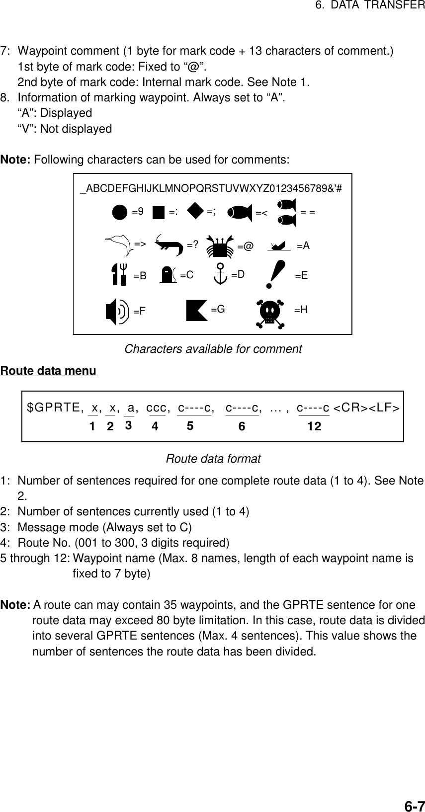
![6. DATA TRANSFER6-6WAYPOINT & ROUTESOFFMARK/LINEOFF▲UPLOADEDITUPLOADSELECTBPSRETURN WIRE INFORMATIONDISPLAY UNIT PC* DSUB9NMEA IN >1>-WHITENMEA IN >2>-BLACKTxD >3>-YELLOW-<2<RDRxD >4>-GREEN -<3<SD+12V >5>-REDEXT BUZZ>6>-BLUEGND >7>-SHIELD-<5<SGRS232C SETTINGS ARE· 4800BPS,· 8BIT,·1STOP BIT,· PARITY NONE.· CONTROL Xon/XoffWAYPOINT & ROUTESOFFMARK/LINEOFF▲DOWN-LOADEDITDOWN-LOADSELECTBPSRETURN WIRE INFORMATIONDISPLAY UNIT PC* DSUB9NMEA IN >1>-WHITENMEA IN >2>-BLACKTxD >3>-YELLOW-<2<RDRxD >4>-GREEN -<3<SD+12V >5>-REDEXT BUZZ>6>-BLUEGND >7>-SHIELD-<5<SGRS232C SETTINGS ARE· 4800BPS,· 8BIT,·1STOP BIT,· PARITY NONE.· CONTROL Xon/XoffUpload and download menus7. To change the baud rate, press the SELECT BPS soft key.BAUD RATE▲▼4800bps9600bps19200bps38400bps57600bpsDEFAULT: 4800bpsBaud rate window8. Select baud rate and press the RETURN soft key.9. Press the DOWNLOAD WPT/RTE or UPLOAD WPT/RTE soft key asappropriate. You are asked if you are ready to download (upload) waypointsand routes.10. Press the [ENTER] knob to download (upload).Waypoint data format1 2 3 4 5 6 77PFEC, GPwpl, llll.llll, a, yyyyy.yyy, a, c----c, c, c----c, a <CR><LF>8Waypoint data format1: Waypoint latitude2: N/S3: Waypoint longitude4: E/W5: Waypoint name (Number of characters is fixed to 6 and space code is placedwhen the number of characters are less than 6.)6: Waypoint color](https://usermanual.wiki/Furuno-USA/9ZWRTR070.OPERATORS-MANUAL-PART4/User-Guide-132139-Page-43.png)
![6. DATA TRANSFER6-8Route comment data format12$PFEC, GPrtc, xx, c----c <CR><LF>Route comment format1: Route No. (01 to 200, 3 digits required)2: Route comment (Max. 16 characters, variable length)The same characters of the comment for waypoint comment can be used.End of sentence$PFEC, GPxfr, CTL, E <CR><LF>End of sentence6.3 Loading Waypoint Data from YeomanConnect the Yeoman equipment to the GPS/NMEA connector on thisequipment and then follow the procedure below:1. Press the [MENU] key.2. Press the SYSTEM CONFIGURATION key.3. Press the DATA TRANSFER soft key.4. Press the RECEIVE DATA BY NavNet soft key.5. You are asked if you are sure to receive waypoint data from yeomanequipment. Press the [ENTER] knob to receive the data.The message “NOW RECEIVING YEOMAN DATA. PUSH SOFTWARE KEY‘STOP’ TO STOP RECEIVING.” Is displayed. If waypoint capacity is reachedthe message “WAYPOINTS ARE FULL. CAN NOT RECEIVE ANY DATA.PUSH ANY KEY TO STOP.” appears.6. To stop receiving, press the STOP soft key.7. After waypoints have been received, press the RETURN soft key followed bythe [MENU] key.](https://usermanual.wiki/Furuno-USA/9ZWRTR070.OPERATORS-MANUAL-PART4/User-Guide-132139-Page-45.png)
![6. DATA TRANSFER6-96.4 Receving Data Via the NavNetYou can receive track, waypoint, routes, marks and lines via NavNet equipmentoutputting such data as below.1. Press the [MENU] key.2. Press the SYSTEM CONFIGURATION soft key.3. Press the RECEIVE DATA BY NavNet soft key.HOST NAMEPLOT1TRACKONWAYPOINTS & ROUTESOFFMARK/LINEOFF▲RECEIVEDATAEDITRCVRETURNReceive data (NavNet) menu4. Select HOST NAME and press the EDIT soft key.HOST NAMEPLOT1Host name window5. Use the [ENTER] knob to input host name and press the RETURN soft key.Use the CLEAR soft key to clear data selected with the cursor.6. Select TRACK and press the EDIT soft key.TRACK▲▼ONOFFTrack window7. Select ON or OFF as appropriate and press the RETURN soft key.8. Turn WAYPOINTS & ROUTES and MARK & LINE on or off as appropriate.](https://usermanual.wiki/Furuno-USA/9ZWRTR070.OPERATORS-MANUAL-PART4/User-Guide-132139-Page-46.png)
![6. DATA TRANSFER6-109. Press the RCV soft key to receive data.The message “NOW RECEIVING DATA.” is displayed. IF no data could befound the message “(HOST NAME)’ IS NOT FOUND.” appears.10. When the transfer is completed, the message “DATA TRANSFERCOMPLETED.” appears. Push the [ENTER] knob to finish.11. Press the [MENU] key to close the menu.](https://usermanual.wiki/Furuno-USA/9ZWRTR070.OPERATORS-MANUAL-PART4/User-Guide-132139-Page-47.png)
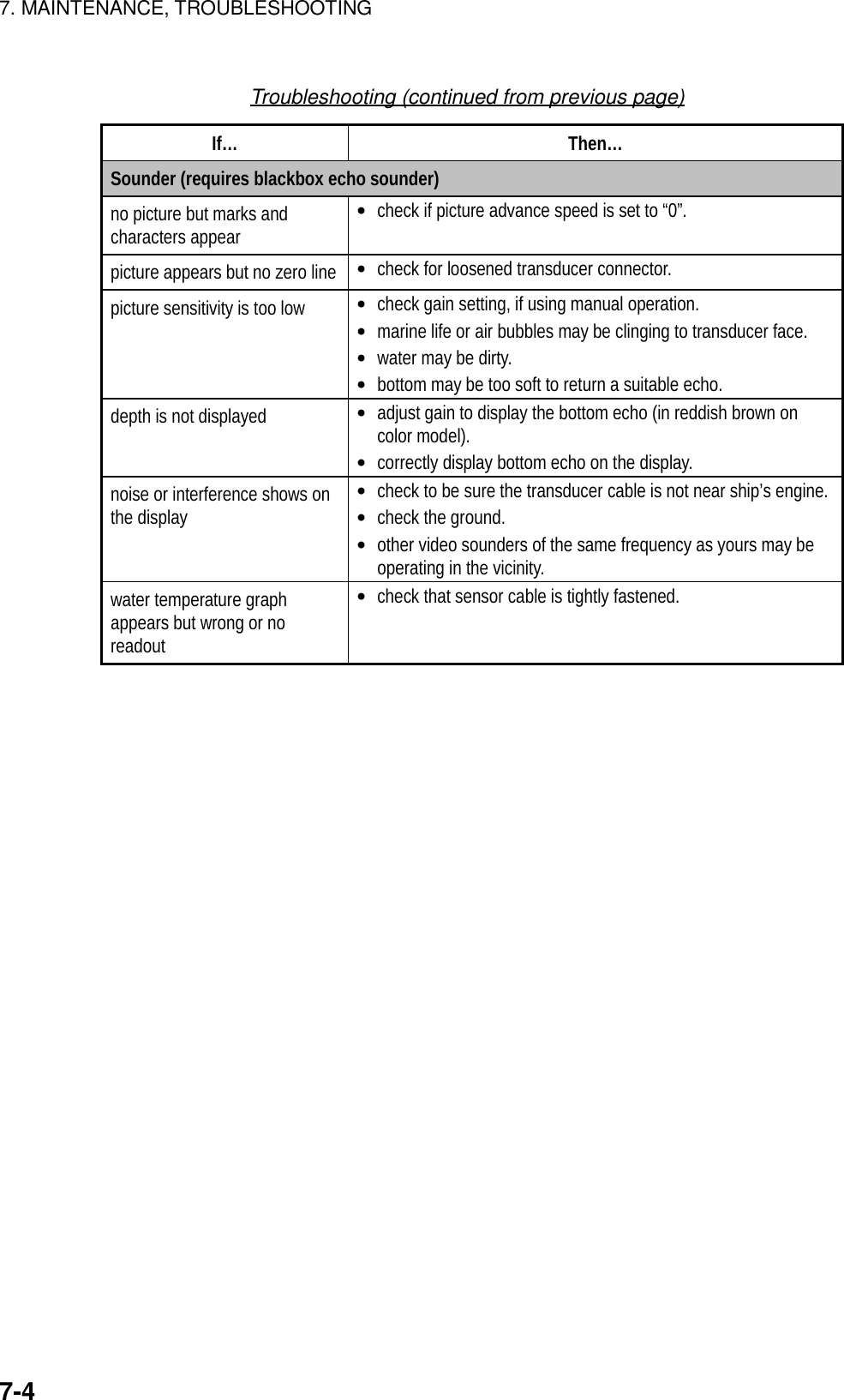
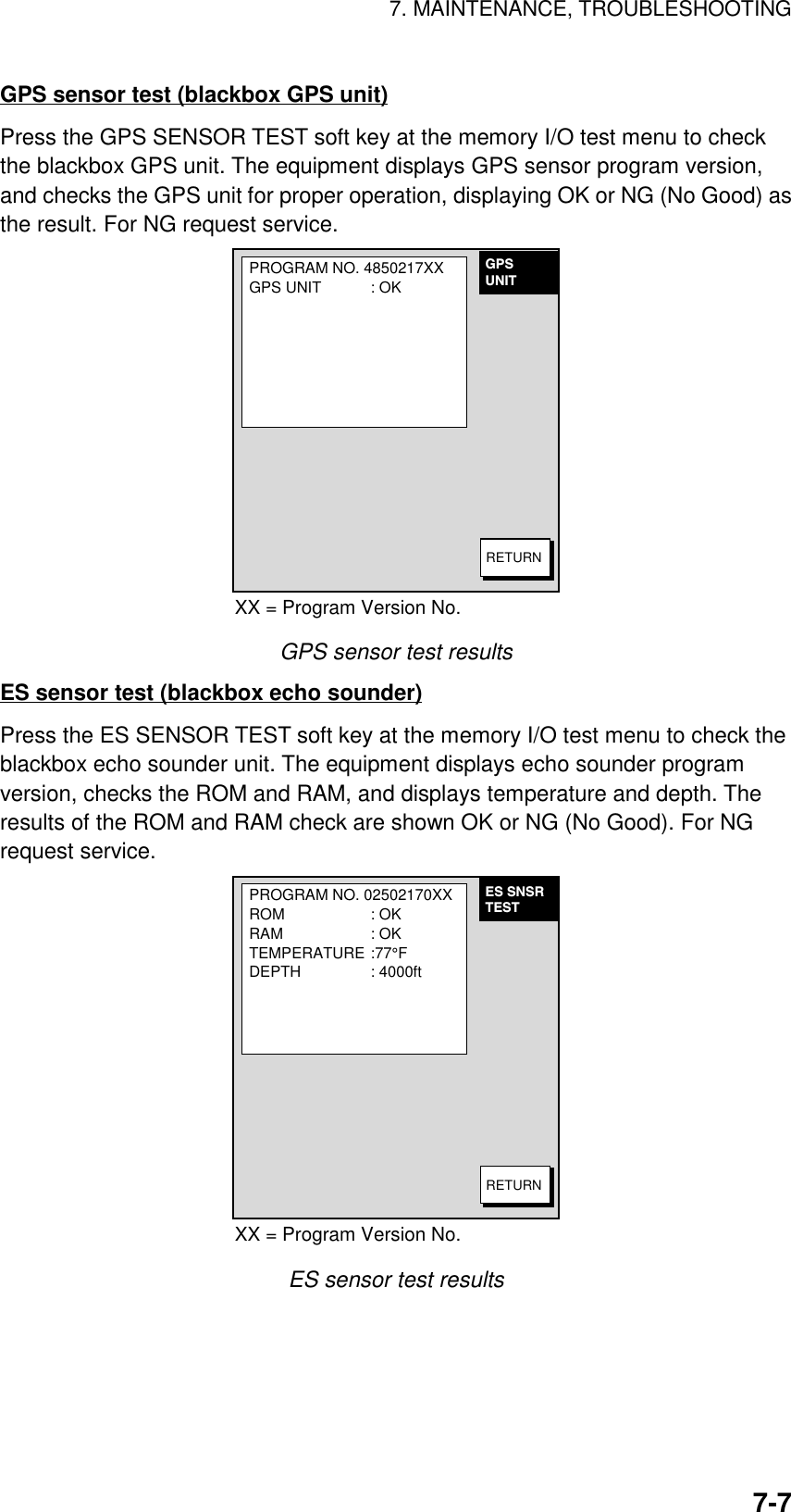
![7. MAINTENANCE, TROUBLESHOOTING7-57.4 DiagnosticsThis paragraph provides the procedures for testing the equipment for properoperation. Four tests are provided: Memory I/O test, Keyboard test, Remotecontroller test, and Test pattern.7.4.1 Displaying the test menu1. Press the [MENU] key to show the menu.2. Press the SYSTEM CONFIGURATION soft key.3. Press the TEST & CLEAR soft key.TEST &MEM CLR MEMORY I/O TESTKEYBOARD & I/R REMOTE TESTTEST PATTERNMEMORY CLEARRETURNTest menu](https://usermanual.wiki/Furuno-USA/9ZWRTR070.OPERATORS-MANUAL-PART4/User-Guide-132139-Page-52.png)
![7. MAINTENANCE, TROUBLESHOOTING7-67.4.2 Memory I/O testThe memory I/O test conducts a general check of the system, displaying variousprogram numbers and device status. Press the [MENU] key followed by theSYSTEM CONFIGURATION and MEMORY I/O TEST soft keys. Then pressappropriate soft key to select a test.MEMORYI/O TST DISPLAY UNIT TESTGPS SENSOR TESTES SENSOR TESTRETURNMemory I/O test menuDisplay unit testPress the DISPLAY UNIT TEST soft key at the memory I/O test menu to test thedisplay unit. The equipment displays program version, checks devices and showthe number of the chart card inserted in the chart slot (if inserted). Results fordevice checks are shown as OK or NG (No Good). For any NG request service. “--“ means no equipment connected.PROGRAM NO. 14512341XXROM : OKSD. RAM : OKS. RAM : OKINTERNAL BATTERY: OKPORT NMEA IN/OUT 1: -- NMEA IN/OUT 2: -- NMEA IN : -- RS232C : -- NETCARD SLOT CHART NO. : JL999DISPLAYUNITRETURNXX = Program Version No.Display unit test results](https://usermanual.wiki/Furuno-USA/9ZWRTR070.OPERATORS-MANUAL-PART4/User-Guide-132139-Page-53.png)
![7. MAINTENANCE, TROUBLESHOOTING7-87.4.3 Test patternThe test pattern test checks the display for proper display of colors (MODEL-1700C series) or tones (MODEL-1700 series).1. Press the [MENU] key to show the menu.2. Press the SYSTEM CONFIGURATION soft key.3. Press the TEST & CLEAR soft key.4. Press the TEST PATTERN soft key.RETURNGREENBLACKBLUEGREENREDWHITEPRESS 'ENTER' TO CHANGEPATTERN.RETURNRETURNMODEL-1700C series MODEL-1700 seriesTest patterns5. For the MODEL-1700C series, press the [ENTER] knob to show white, red,green, blue and black colors.6. Press the RETURN soft key to finish.7. Press the [MENU] key to close the menu.](https://usermanual.wiki/Furuno-USA/9ZWRTR070.OPERATORS-MANUAL-PART4/User-Guide-132139-Page-55.png)
![7. MAINTENANCE, TROUBLESHOOTING7-97.4.4 Keyboard testThe keyboard test checks all the controls for proper operation.1. Press the [MENU] key to show the menu.2. Press the SYSTEM CONFIGURATION soft key.3. Press the TEST & CLEAR soft key.4. Press the KEYBOARD & I/R REMOTE TEST soft key.RMTCNTLTESTRMTC CODEA523K-BOARDTESTScreen for testing keyboard, remote controller5. Operate each control on the keyboard or remote controller one by one. A keyis functioning properly if its on-screen location “lights” when the key is pressed.The digits at the on-screen location for the [ENTER] knob on the display unitincrement upward or downward with clockwise and counterclockwise rotationof the knob, respectively.6. Press the [CLEAR] key three times to escape from the test.7. Press the [MENU] key to close the menu.](https://usermanual.wiki/Furuno-USA/9ZWRTR070.OPERATORS-MANUAL-PART4/User-Guide-132139-Page-56.png)
![7. MAINTENANCE, TROUBLESHOOTING7-107.5 GPS Monitor DisplayThe GPS monitor provides data about the GPS satellites.1. Press the [DISP] key to show the plotter display.2. Press the [MENU] key.3. Press SYSTEM CONFIGURATION, NAV OPTIONS and GPS UNIT SETUPsoft keys to display the GPS SETUP menu.4. Press the soft key GPS MON.RETURNDOP1.2GPS 3DHEIGHT22m 23:59:5931.SEP.00E123456789101112454545454545454545454545NSW101229813675114GPS fix stateDateDOP valueEstimated position in the sky, and satellite number in reverse video is used for positioning.Receive signal levelBars show satellitesignal level. Satellitesextends past the dashed line are usedin fixing position.GPS antenna heightGPS monitor display](https://usermanual.wiki/Furuno-USA/9ZWRTR070.OPERATORS-MANUAL-PART4/User-Guide-132139-Page-57.png)
![7. MAINTENANCE, TROUBLESHOOTING7-117.6 Clearing MemoriesYour equipment has a memory bank for each of the plotter, radar and soundersections. These memories can be cleared collectively or individually to startoperation afresh, with default settings.1. Press the [MENU] key to open the menu.2. Press the CONFIGURATION soft key.3. Press the USER OPTION soft key.4. Press the MEMORY CLEAR soft key.MEMORYCLEAR DISPLAY UNIT CLEARGPS UNIT CLEARES SENSOR UNIT CLEARRETURNNONONOEDITMemory clear menu5. Select the memory to clear.6. Press the EDIT soft key. One of the following displays appear.CLEAR WPT/RTE DATA ANDMARK/LINE DATA. AND SETDEFAULT OUT OF SOUNDERUNIT SETTING. ARE YOUSURE?YES...'ENTER' KEYNO ...'CLEAR' KEYDISPLAY UNIT CLEAR GPS UNIT CLEAR SOUNDER UNIT CLEARCLEAR GPS MEMORY ANDBEGIN COLD START.ARE YOU SURE?YES...'ENTER' KEYNO ...'CLEAR' KEYSOUNDER1* : WILL SETDEFAULT SETTING.ARE YOU SURE?YES...'ENTER' KEYNO ...'CLEAR' KEY*: ETR HOST nameWindows for clearing memory7. Select YES and press the ENTER soft key. You are asked if you are sure toclear the memory.8. Push the [ENTER] knob to clear the memory.](https://usermanual.wiki/Furuno-USA/9ZWRTR070.OPERATORS-MANUAL-PART4/User-Guide-132139-Page-58.png)