Furuno USA 9ZWRTR100 Transceiver for Radar model FAR-1518/1528 User Manual OME 36380 A
Furuno USA Inc Transceiver for Radar model FAR-1518/1528 OME 36380 A
Contents
- 1. Installation Manual Part 3
- 2. Installation Manual Part 1
- 3. Installation Manual Part 2
- 4. Installation Manual Part 4
- 5. Installation Manual Part 5
- 6. Installation Manual Part 6
- 7. User Manual Part 1
- 8. User Manual Part 2
- 9. User Manual Part 3
- 10. User Manual Part 4
- 11. User Manual Part 5
- 12. User Manual Part 6
User Manual Part 1

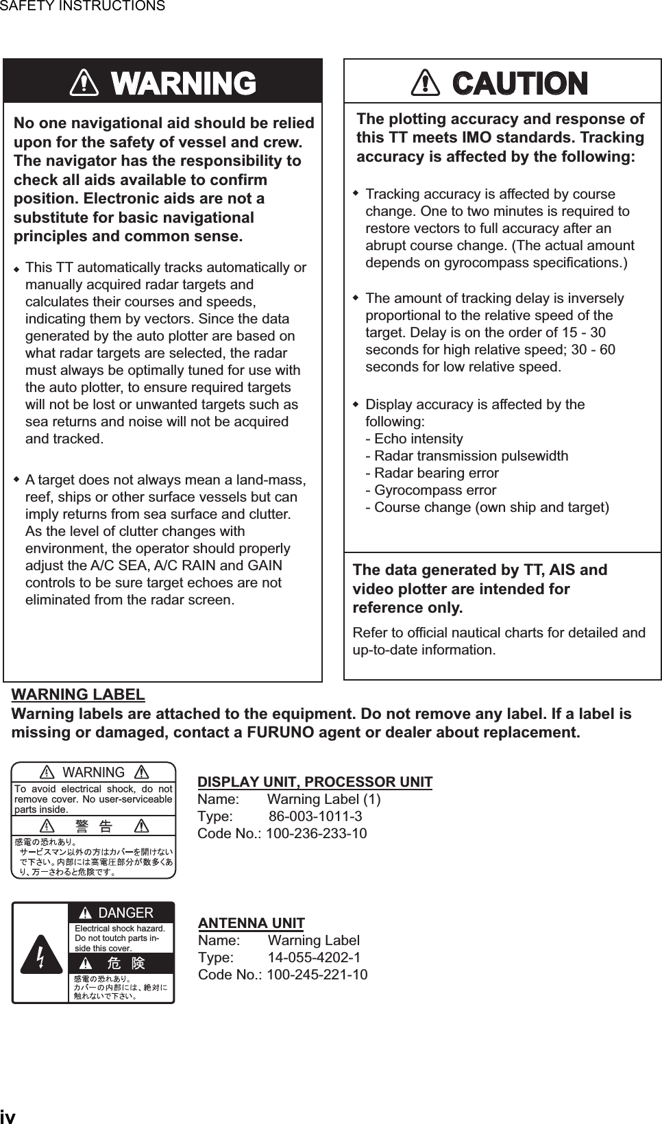

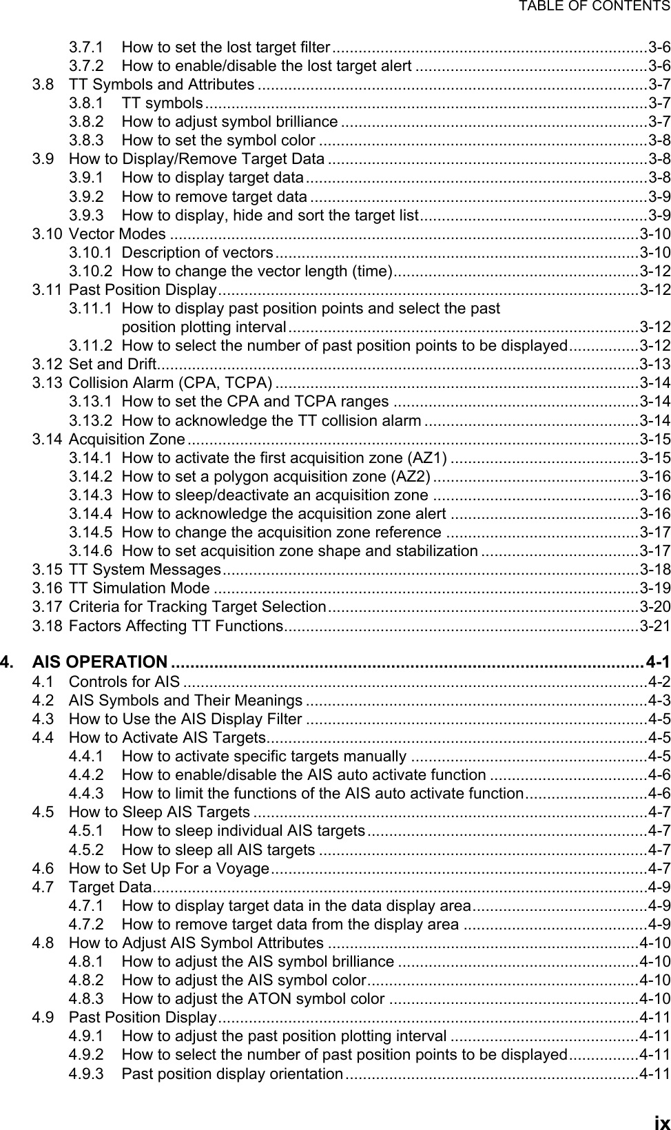
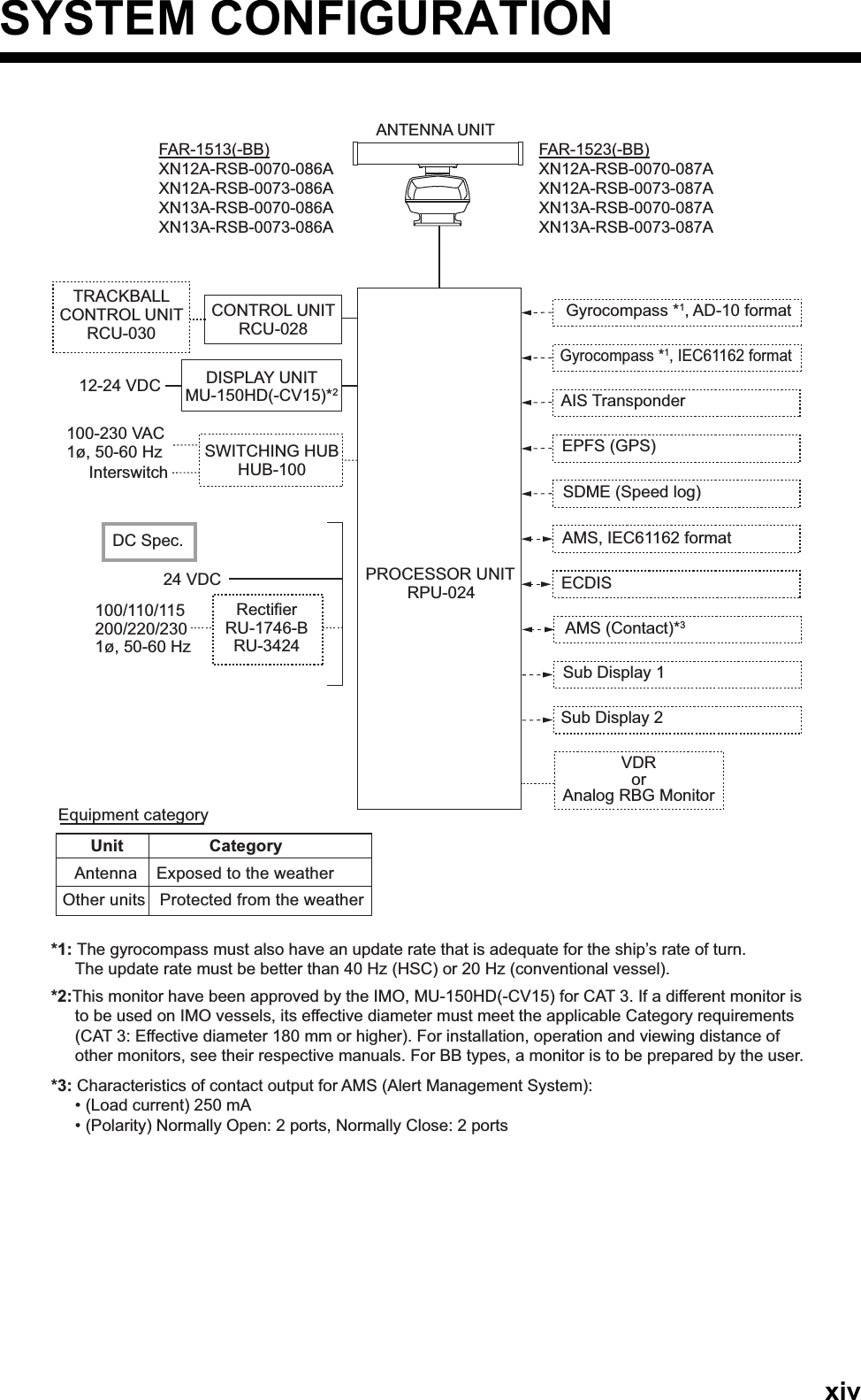

![1. OPERATIONAL OVERVIEW1-21.1.1 Trackball unit RCU-030 (Option)The optional trackball unit can be used to control most features of this radar.1.1.2 Terminology used in this manualThis manual uses the following terminology:For the sake of brevity, procedures in this manual use the terms “Open the [MAIN MENU].” and “Close the menu.”All operations can be done with either the RCU-030 trackball unit or the RCU-028 con-trol unit.Throughout this manual, procedures are outlined using the RCU-028 control unit, unless otherwise specified.Terminology MeaningSelect • Using the touchpad or trackball, move the cursor over the item to be “selected”.• Rotate the ADJUST knob to highlight the item to be “selected”.Left-click Press the left button on the RCU-030 unit.Right-click Press the right button on the RCU-030 unit.Left button Refers to the left button ( ) on the RCU-028 control unit.Right button Refers to the right button ( ) on the RCU-028 control unit.Control unit Refers to the RCU-028 control unit.Trackball Refers to the RCU-030 control unit.Open the [MAIN MENU]. • Press the key to open the main menu. • Select the [MENU] box, then press the left button or left-click.Close the menu. • Press the key to close the menu. (Closes all open menus.)• Select the operational display area, then press the right button or right-click.• Select the [MENU] box, then press the left button or left-click.TrackballRightbuttonScrollwheelLeftbuttonLeftbuttonLeft Button- Does the operation related to the selected object.- Confirms the operation for the selected object.Scrollwheel- Selects menu options.- Sets numeric data.- Sets menu box slide bars (GAIN, etc.)Note: The scrollwheel does not have a “push” functionRight Button- Cancels current action.- Opens/closes menu boxes.Trackball- Moves cursor.- Highlights an object (target echo, menu item, etc.)](https://usermanual.wiki/Furuno-USA/9ZWRTR100.User-Manual-Part-1/User-Guide-2768720-Page-19.png)
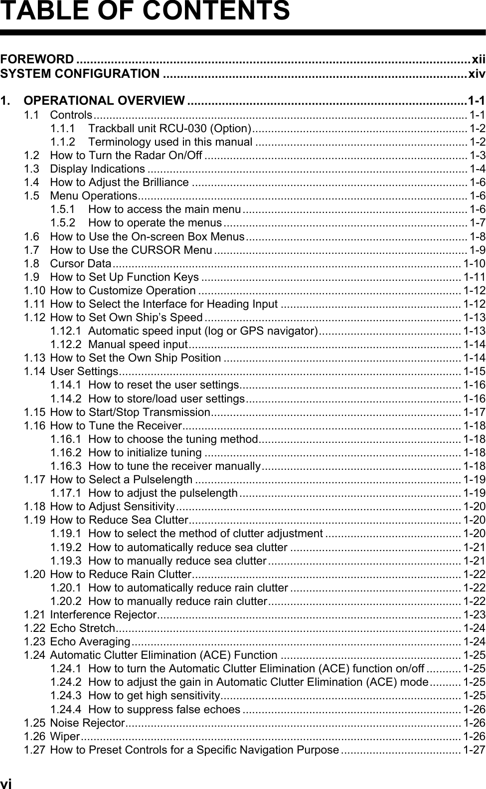
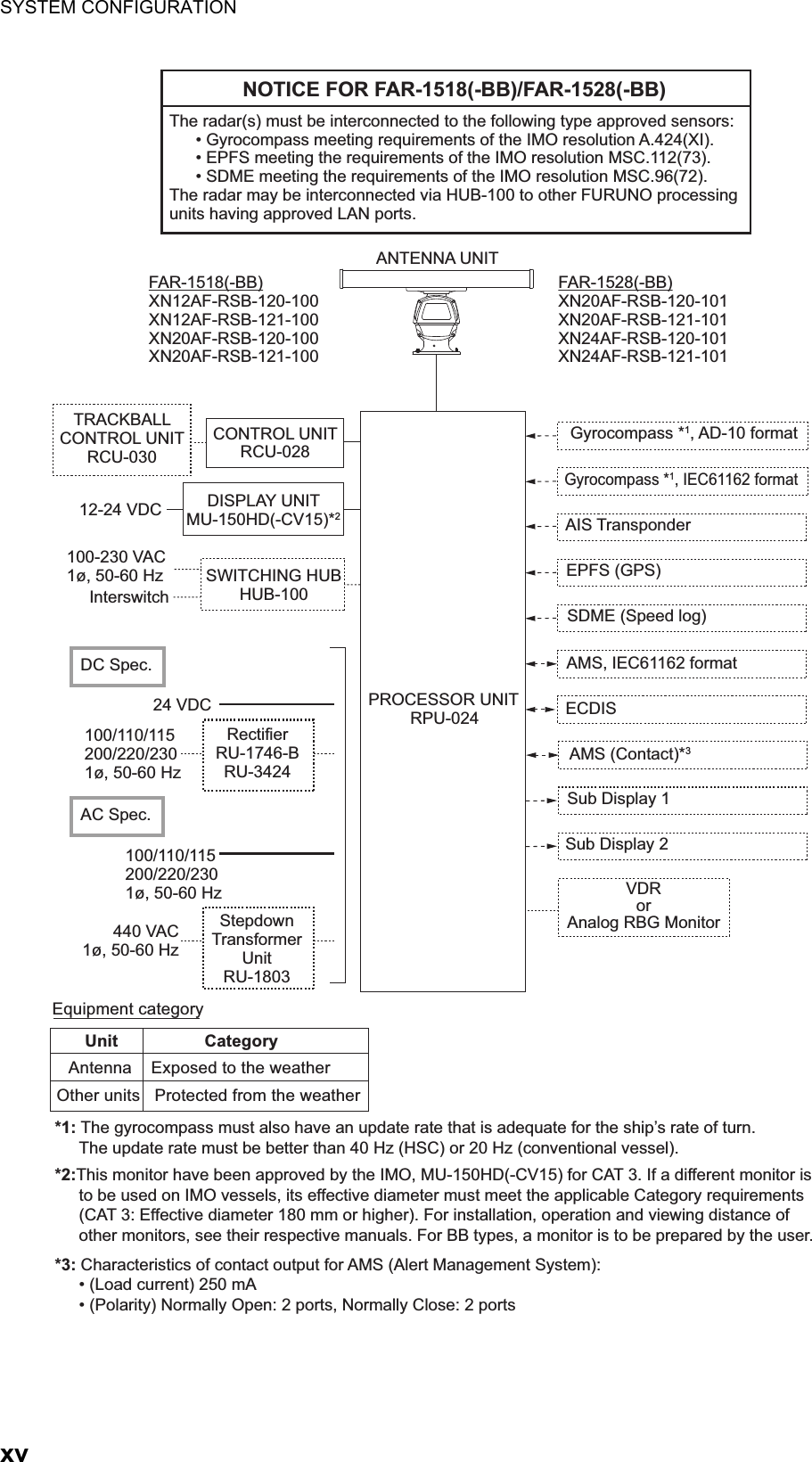
![1. OPERATIONAL OVERVIEW1-31.2 How to Turn the Radar On/OffThe POWER switch is located at the bottom left corner of the control unit. Open the POWER switch cover and press the switch to turn the radar system on. To turn the system off, press the POWER switch again. The screen shows the bearing scale and digital timer for approximately 30 seconds after power is applied. The timer counts down three minutes of warm-up time. During this period, the magnetron (transmitter tube) is warmed for transmission. When the timer has reached 0:00, the indication "ST-BY" appears at the screen center, meaning the radar is now ready to transmit pulses.In the stand-by condition, markers, rings, maps, etc. are not shown. Further, TT and AIS are not shown. In the warm-up and stand-by conditions, [ON TIME] and [TX TIME] are counted in hours and tenths of an hour, appearing at the screen center.Note 1: Do not turn on the power directly after it has been turned off. Wait several seconds before you reapply the power, to be sure the radar starts up properly.Note 2: Parameters set on the menus are stored in a non-volatile memory (flash memory), and are preserved when the power is turned off.Note 3: The screen refreshes slower in low ambient temperature.](https://usermanual.wiki/Furuno-USA/9ZWRTR100.User-Manual-Part-1/User-Guide-2768720-Page-20.png)
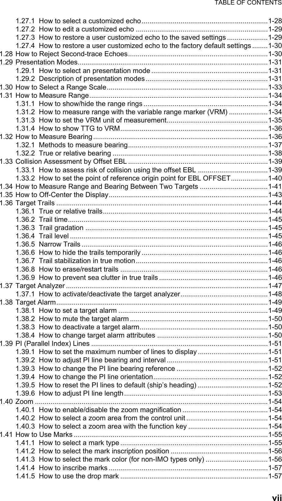
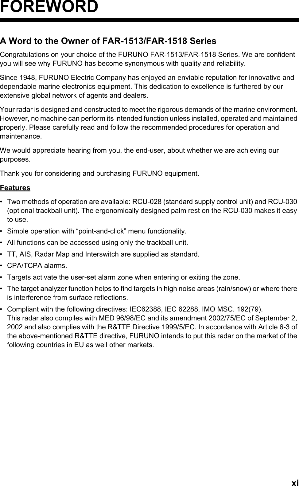
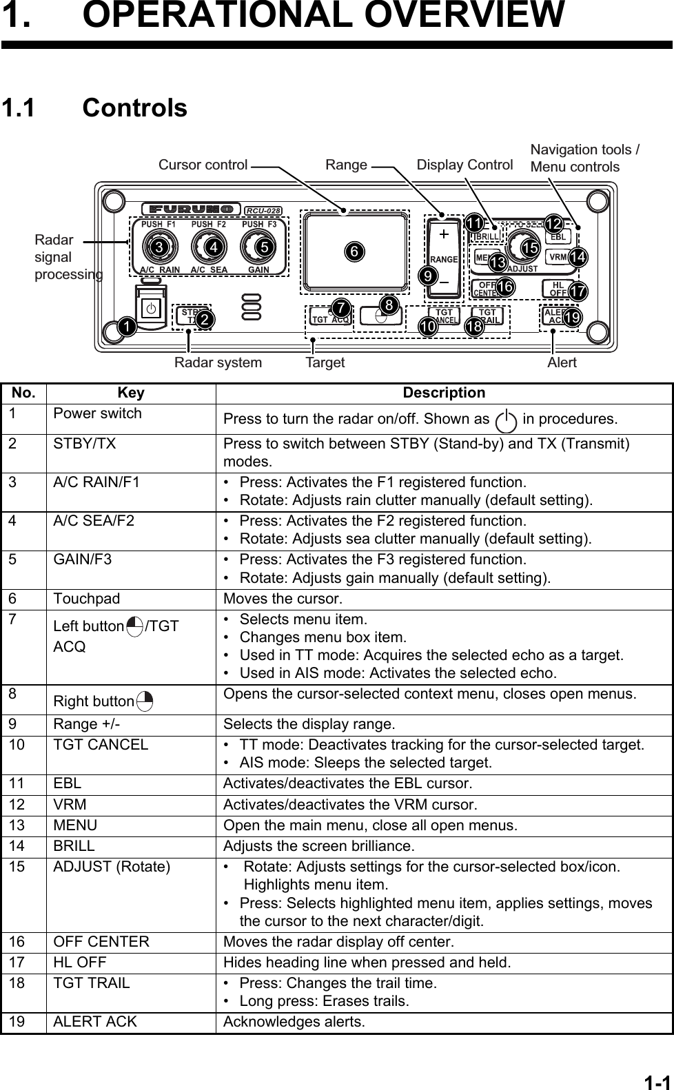
![1. OPERATIONAL OVERVIEW1-41.3 Display IndicationsNo. Name Description1 STBY/TX box Switches between standby and transmit mode.2 Range box Changes the radar range.3 CU/TM Reset box Resets display when using Course Up/True Motion presentation mode.4 REF POINT box Changes the reference point.5 GAIN box Adjusts the GAIN level.6 SEA box Adjusts the A/C SEA settings.7 RAIN box Adjusts the A/C RAIN settings.8 TUNE box Adjusts the tuning for the receiver.9 Cursor information box Displays the range, bearing and TTG to cursor position.10 Cursor position box Displays the cursor’s current co-ordinates.11 MAP ALIGN box Enable/disable radar map alignment.12 MENU box Opens the [MAIN MENU].763334353635383754317 17141516181920212227243229262325302831128910111213](https://usermanual.wiki/Furuno-USA/9ZWRTR100.User-Manual-Part-1/User-Guide-2768720-Page-21.png)
![1. OPERATIONAL OVERVIEW1-5Display specifications13 USER SET Load/save user specific settings.14 TGT List Displays the target list, displays the [TARGET LIST] menu.15 AZ box Activates/deactivates the acquisition zone(s).16 VRM box Activate/deactivate the VRM.17 DROP box Displays drop mark data.18 EBL box Activate/deactivate the EBL19 PI Line box Activate/deactivate the PI lines.20 MARK boxes Select mark icons, displays mark information.21 MAP box Activate/deactivate the radar map.22 BRILL box Adjust screen brilliance, opens the [BRILLIANCE] menu.23 HL OFF box Hides the heading line.24 IR box Activate/deactivate the interference rejector function.25 ES box Activate/deactivate the echo stretch function.26 NR box Activate/deactivate the noise reduction function.27 EAV box Activate/deactivate the echo averaging function.28 ACE box Activate/deactivate the ACE function.29 CUSTOMIZE ECHO box Cycle through echo filtering customizations, open the [CUSTOMIZE ECHO] menu.30 PULSE box Cycle through pulse settings.31 ANTENNA SELECT box Selects the antenna to use. Only antennas connected to the same network are displayed and selectable.32 PRESENTATION MODE box Cycle though display presentation modes.33 Own ship details box. Shows various data regarding own ship. Contains speed*, heading and position context menus.*: Speed is displayed as a negative value when the vessel is using reverse thrust.34 Information box • Displays currently open menu.• Displays various information, such as received messages, TT/AIS target information and navigational data.35 TT/AIS box • Activate/deactivate TT/AIS functions.• Access TT/AIS functions such as filters and association.• Access the [AIS TARGET MENU].• Access the [TT MENU].• Displays/sets target vector time and orientation.36 TRAIL box • Set target trail time.• Set past position plotting interval.• Erases trails• Opens [TRAIL] menu.37 Alert box Displays alert information and icons.38 Guidance box Displays operational guidance for selected item.• Left side: guidance for left button/left-click.• Right side: guidance for right button/right-click.Working indicator Rotates clockwise when the system is working properly.Picture freezeIf the picture freezes, the picture is not updated. Restart (turn off, then on) the unit to restore normal operation.• Nominal viewing distance: 0.75 m• Text height: 2.67 mm• Text width: 2.08 mmNo. Name Description](https://usermanual.wiki/Furuno-USA/9ZWRTR100.User-Manual-Part-1/User-Guide-2768720-Page-22.png)
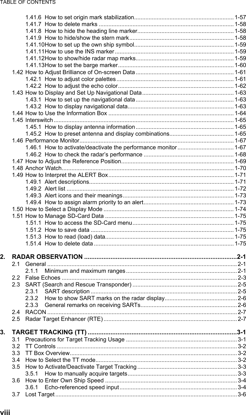
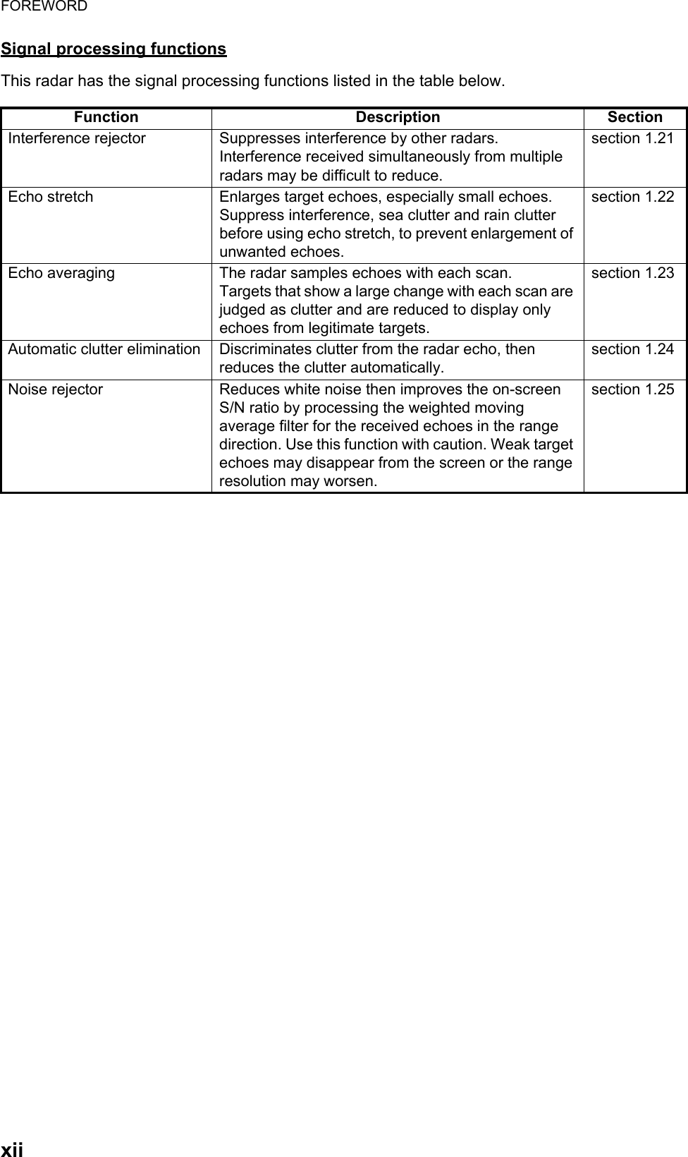
![1. OPERATIONAL OVERVIEW1-61.4 How to Adjust the BrillianceThe screen brilliance can be adjusted as shown below. To adjust color tones, see "How to adjust color palettes" on page 1-61.Note: External monitor brilliance is not adjustable from the radar. Refer to the external monitor’s Operator’s Manual for how to adjust brilliance.From the control unit1. Press the key. The cursor is automatically moved to the [BRILL] box.2. Use the ADJUST knob to adjust the brilliance as appropriate. Turn clockwise to increase the brilliance, counter-clockwise to reduce the brilliance. Press the ADJUST knob to complete the adjustments.From the on-screen box1. Use the Touchpad to select the [BRILL] box, then press the left button.2. Use the ADJUST knob to adjust the brilliance as appropriate. Turn clockwise to increase the brilliance, counter-clockwise to reduce the brilliance. Press the ADJUST knob to complete the adjustments.1.5 Menu Operations1.5.1 How to access the main menuThe main menu can be accessed from the control unit or from the on-screen box. The [MAIN MENU] is displayed in the text area on the right side of the screen.From the control unitPress the key on the control panel. From the on-screen boxSelect the [MENU] box, then press the left button.Brilliance barShows brilliance level.[MAIN MENU]1 [ECHO]2 [MARK]3 [NAVTOOL]4 [ALERT]5 [TT•AIS]6 [FILES]7 [INFORMATION BOX]8 [NAV LINE•WPT]9 [INITIAL SETTING]0 [RADAR INSTALLATION]Echo processing functionsMainly turns markers on/off.Navigation tools (PI lines/EBL/VRM)Sets target alarm functions; outputs alert signal.Sets TT and AIS functions.Manages stored data.Sets data display box items.Processes nav lines and waypoints.Sets up the radar, changes function key settings.Used by technicians and service personnel.](https://usermanual.wiki/Furuno-USA/9ZWRTR100.User-Manual-Part-1/User-Guide-2768720-Page-23.png)
![1. OPERATIONAL OVERVIEW1-71.5.2 How to operate the menus1. Open the [MAIN MENU].2. Rotate the ADJUST knob to select a layer one ([MAIN MENU]) menu item, then press the ADJUST knob. The menu item currently selected is highlighted and shown in reverse video.3. Rotate the ADJUST knob to select the layer two menu item, then press the knob.Repeat this step to access the layer three menu. In the above example, [ACE] is selected, which opens the layer three [ACE] menu.4. Rotate the ADJUST knob to adjust the selected setting, then press the knob.5. Close the menu.[ECHO]1 BACK2 2nd ECHO REJ OFF / ON3 TUNE INITIALIZE4 PERFORMANCE MON OFF / ON5 PM ARC 2 / 3 / 5 / 66 SART OFF / ON7 ECHO AREA CIRCLE /WIDE / ALL / SIMPLE8 WIPER OFF / 1 / 29 [ACE]0 [CUSTOM SELECT][ACE]1 BACK2 SIGNAL ENHANCEMENT 1 / 2 / 33 SUPPRESS SECTOR START : 000 ANGLE : 000[MAIN MENU]1 [ECHO]2 [MARK]3 [NAVTOOL]4 [ALERT]5 [TT•AIS]6 [FILES]7 [INFORMATION BOX]8 [NAV LINE•WPT]9 [INITIAL SETTING]0 [RADAR INSTALLATION]Menu selection is highlighted and in reverse video.Layer one (MAIN MENU) Layer two Layer three](https://usermanual.wiki/Furuno-USA/9ZWRTR100.User-Manual-Part-1/User-Guide-2768720-Page-24.png)
![1. OPERATIONAL OVERVIEW1-81.6 How to Use the On-screen Box MenusSome radar functions can be accessed using the on-screen box menus. A “” at the right side of an on-screen box which indicates that there is a box menu.There are two methods for on-screen box menu selection.• Use the Touchpad to select the on-screen box, then press the right button.• Use the trackball unit (RCU-030) to select the on-screen box, then right-click.The procedure outlined below uses the RCU-028 control unit.To operate the radar using the on-screen boxes, do the following:1. Select the desired box.Note: The cursor changes shape according to its location. It is an arrow when placed outside the operational display area and when inside the operational display area, it is a cross .For the purpose of this example, select the [BRILL] box, at the bottom left corner of the display.When a box is correctly selected, its color changes and the guidance box at the bottom right corner shows operational guidance. The operational guidance shows the function of the left button and right buttons, with a diagonal line separating the information.The [BRILL] box, for example, displays the operational guidance "BRILL SELECT / BRILL MENU". In this case you would press the left button to select a preset palette (See "How to adjust color palettes" on page 1-61) or press the right button to open the [BRILL] menu.2. Press the left button to cycle through preset palettes.3. Rotate the ADJUST knob to adjust the display brilliance.4. The box menu attached to the [BRILL] box is the [BRILL] menu. To open the box menu, press the right button.5. Select the desired menu item, then press the ADJUST knob. 6. Select the appropriate option, then press the ADJUST knob.7. Close the menu.Place cursor here, then press the left button to change brilliance preset, right button to open the [BRILL] menu.](https://usermanual.wiki/Furuno-USA/9ZWRTR100.User-Manual-Part-1/User-Guide-2768720-Page-25.png)
![1. OPERATIONAL OVERVIEW1-91.7 How to Use the CURSOR MenuFunctions that require the use of the cursor, such as EBL offset and zoom, can be activated directly from the guidance box or from the [CURSOR] menu, either method with the cursor inside the operational display area. Below is the procedure for choosing cursor-related functions from the [CURSOR] menu.1. Select the operational display area, then press the right button.The [CURSOR] menu is displayed.2. Select the desired function, then press the ADJUST knob.3. The guidance box shows "XX / EXIT" (XX = function selected). Use the Touchpad to place the cursor where desired.4. Press the ADJUST knob to execute the function selected at step 3.5. To quit the selected function, press the right button when the guidance box shows "XX / EXIT" (XX = function selected).Menu Item DescriptionTARGET DATA & ACQ TT: Acquires target; displays data for selected tracked target.AIS: Activates sleeping AIS target; display data for selected AIS target.TARGET CANCEL TT: Cancels tracking on selected tracked target.AIS: Sleeps selected AIS target.TT TGT DATA & ACQ Acquires selected echo as tracked target.REF MARK Inscribes reference mark, for target-based speed input.EBL OFFSET Offsets EBL to measure range and bearing between two targets.OFFCENTER Shifts screen center to selected location.ZOOM Zooms selected location.MARK DELETE Deletes selected mark (plotter mark, origin mark or waypoint mark).OWN TRACK DELETE Deletes own ship's tracks.MAP ALIGN Aligns charts (maps) with the radar picture.TRAIL ERASER Erases trails.CURSOR SIZE Selects cursor size.TARGET DATA/ACQ SETTING Adjust target tracking settings.TARGET CANCEL SETTING Adjust target cancel settings.[CURSOR MENU]TARGET DATA & ACQTARGET CANCELTT TGT DATA & ACQREF MARKEBL OFFSETOFFCENTERZOOMMARK DELETEOWN TRACK DELETEMAP ALIGNTRAIL ERASERCURSOR SIZETARGET DATA/ACQ SETTINGTARGET CANCEL SETTING](https://usermanual.wiki/Furuno-USA/9ZWRTR100.User-Manual-Part-1/User-Guide-2768720-Page-26.png)
![1. OPERATIONAL OVERVIEW1-101.8 Cursor DataCursor data can be shown in latitude and longitude position or the cursor’s X-Y coordinates.Place cursor on the [CURSOR DATA] box at the right side of the display then press the left button. The data box shows the cursor information in the upper half and cur-sor location (latitude/longitude) is shown in the lower half.Note 1: For the X-Y coordinates display, the Y-axis is the heading line, the upper half of the screen is “plus” and the lower part of the screen is “minus”. The X-axis is the port/starboard direction, starboard is “plus”, port is “minus”.Note 2: When displaying latitude and longitude position and the cursor has been aligned (on the [CURSOR] menu), the indication "MAP ALIGN" appears at the right side of the screen (in yellow).Note 3: Cursor data reads "- - -.-" when the cursor is placed outside the operational display area.CURS 099 . 1°T00:32 5.317NM33°59.156N135°06.328ECURS 6.087km01:08 3.997km33°59.156N135°06.328EBearing/range displayedCursor’s X-Y coordinates displayedPress the left button to switch between display formatsTTG to cursor positionBearing/range to cursor position.TTG to cursor position Cursor positon’s latitude/longitudeRange to cursor’s X-Y location.](https://usermanual.wiki/Furuno-USA/9ZWRTR100.User-Manual-Part-1/User-Guide-2768720-Page-27.png)
![1. OPERATIONAL OVERVIEW1-111.9 How to Set Up Function KeysSome menu functions and menus can be assigned to a function key. This allows one-touch access to the assigned function or menu.To activate an assigned function, press the corresponding function key (F1, F2 or F3).The function keys are preset with the following functions:F1: A/C RAIN, F2: A/C SEA, F3: ACE (Gain).You can customize the function set to each key using the following procedure.1. Open the [MAIN MENU].2. Select [INITIAL SETTING], then press the ADJUST knob.3. Select [FUNCTION KEY], then press the ADJUST knob.4. Select [F1], [F2] or [F3] as appropriate, then press the ADJUST knob.5. Referring to the table of available functions below, select a function category, then press the ADJUST knob. *: Non-IMO radars only.6. Select the appropriate function to be assigned, then press the ADJUST knob.7. Close the menu. Repeat the procedure as necessary to set up other function keys.Function category Available functionECHO CUSTOM MENU, IR, ES, EAV, NOISE REJ, ANT SELECT, PULSE LENGTH, AUTO-SEA, AUTO-RAIN, TUNE SELECT, 2ND ECHO REJ, PM, SART, ECHO TRAIL, TRAIL T/R, WIPER, ACE, ACE HIGH SENSITIVITYSTD KEY ALERT ACK, STBY TX, EBL OFFSET, PRESENTATION MODE, CU-TM RE-SET, VECTOR TIME, VECTOR MODE, TARGET LIST, BRILL, MARK-CUR-SOR, MARK-OS, MENU, RANGE UP, RANGE DOWN, ACQ, TARGET DATA, TARGET CANCELTT•AIS TT-DISP, AIS-DISP, PAST POSN INTERVAL, REF MARK, CPA LIMIT, CPA, TCPA, AZ1, AZ2, AIS SCALED SYMBOLDELETE DATA MARK DELETE, MARK ALL DELETE, OWN TRACK DELETE, OWN TRACK ALL DELETEOPERATION ECHO AREA*, ECHO COLOR, RING(ON/OFF), ZOOM, MOB, ALARM1, ALARM2, TLL, MAP ALIGN](https://usermanual.wiki/Furuno-USA/9ZWRTR100.User-Manual-Part-1/User-Guide-2768720-Page-28.png)