GE MDS DS-EL806-24 2.4 GHz TransNet User Manual xxxxA TNET2 4 OEM Body
GE MDS LLC 2.4 GHz TransNet xxxxA TNET2 4 OEM Body
GE MDS >
Contents
- 1. Users Manual Part 1
- 2. Users Manual Part 2
- 3. Users Manual Part 3
- 4. Users Manual Part 4
Users Manual Part 3
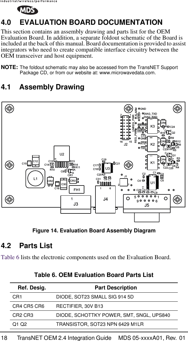
![24 TransNET OEM 2.4 Integration Guide MDS 05-xxxxA01, Rev. 01 7.1 Antenna AimingFor optimum performance of directional antennas (yagis), they must be accurately aimed in the direction of desired transmission. The easiest way to do this is to point the antenna in the approximate direction, then use the remote radio’s RSSI command (Received Signal Strength Indicator) to further refine the heading for maximum received signal strength.In an MAS system, RSSI readings are only meaningful when initiated from a remote station. This is because the master station typically receives signals from several remote sites, and the RSSI would be continually changing as the master receives from each remote in turn.7.2 Antenna SWR CheckIt is necessary to briefly key the transmitter for this check by placing the radio in the SETUP mode (Page 49) and using the KEY command. (To unkey the radio, enter DKEY; to disable the SETUP mode and return the radio to normal operation, enter Q or QUIT.)The SWR of the antenna system should be checked before the radio is put into regular service. For accurate readings, a wattmeter suited for 2.4 GHz is required. One unit meeting this criteria is the Bird Model 43 directional wattmeter with an appropriate element installed.The reflected power should be less than 10% of the forward power (≈2:1 SWR). Higher readings usually indicate problems with the antenna, feedline or coaxial connectors.7.3 Data Buffer SettingThe default setting for the data buffer is OFF. This allows the radio to operate with the lowest possible latency and improves channel efficiency. MODBUS and its derivatives are the only protocols that should require the buffer to be turned on. See “BUFF [ON, OFF]” on Page 42 for details.7.4 Hoptime SettingThe default hop-time setting is 7 (7 ms). An alternate setting of 28 is used to increase throughput, but at the cost of increased latency. A detailed explanation of the HOPTIME command can be found on Page 44.7.5 Operation at 115200 bpsBurst throughput at 115200 bps is supported at all settings. The radio will always buffer at least 500 characters. Sustained throughput at 115200bps is only possible when the data path is nearly error free and the operating settings have been properly selected. For sustained operation at 115200 bps, use the following settings: SAF OFF, FEC OFF, REPEAT 0, RETRY 0, HOPTIME 28.](https://usermanual.wiki/GE-MDS/DS-EL806-24.Users-Manual-Part-3/User-Guide-411409-Page-7.png)
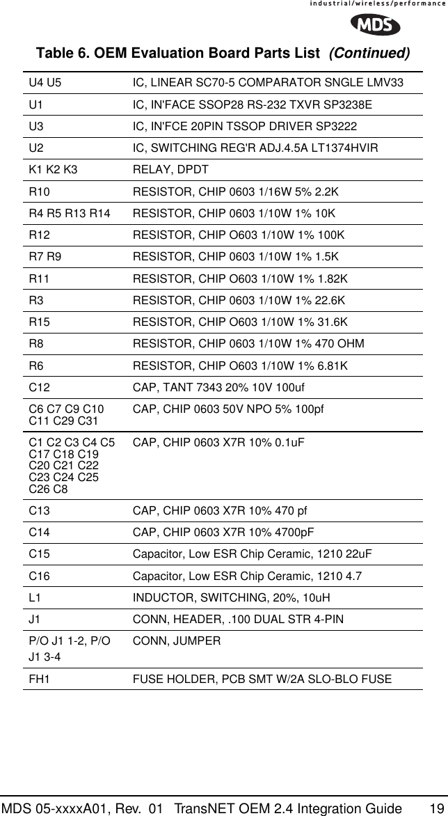
![32 TransNET OEM 2.4 Integration Guide MDS 05-xxxxA01, Rev. 01 It is important to note that power consumption will increase somewhat as communication from the master station degrades. This is because the radio will spend a greater period of time “awake” looking for synchronization messages from the master radio.In order for the radio to be controlled by the Sleep Mode pin, the radio must be set to SLEEP ON. See “SLEEP [ON, OFF]” on Page 50 for more information.Sleep Mode ExampleThe following example describes Sleep Mode implementation in a typical system. Using this information, you should be able to configure a system that meets your own particular needs.Suppose you need communications to each remote site only once per hour. Program the RTU to raise an EIA/RS-232 line once each hour (DTR for example) and wait for a poll and response before lowering it again. Connect this line to Pin 6 of the radio’s header connector. This will allow each RTU to be polled once per hour, with a significant savings in power consumption.9.0 DEALING WITH INTERFERENCEThe transceiver shares the frequency spectrum with other services and other Part 15 (unlicensed) devices in the USA. As such, near 100% error free communications may not be achieved in a given location, and some level of interference should be expected. However, the radio’s flexible design and hopping techniques should allow adequate performance as long as care is taken in choosing a suitable location and in configuring the radio’s operating parameters.In general, keep the following points in mind when setting up your communications network:1. Systems installed in rural areas are least likely to encounter interference; those in suburban and urban environments are more likely to be affected by other devices operating in the license-free frequency band and by adjacent licensed services.2. If possible, use a directional antenna at remote sites. They confine the transmission and reception pattern to a narrow lobe, which minimizes interference to (and from) stations located outside the pattern.3. If interference is suspected from a nearby licensed system (such as a paging transmitter), it may be helpful to use horizontal polarization of all antennas in the network. Because most other services typically use vertical polarization in this band, an additional 20 dB of attenuation to interference can be achieved by using the horizontal plane.4. Multiple spread spectrum systems can co-exist in close proximity to each other with only minor interference, provided they are each assigned a unique network address. Each network address has a different hop pattern associated with it.](https://usermanual.wiki/GE-MDS/DS-EL806-24.Users-Manual-Part-3/User-Guide-411409-Page-15.png)