GE MDS DS-MERCURY900 Mercury 900 Wireless Transceiver User Manual
GE MDS LLC Mercury 900 Wireless Transceiver
GE MDS >
Contents
- 1. manual pt 1
- 2. manual pt 2
- 3. User Manual 1
- 4. User Manual 2
- 5. Users Manual Revised 121908 Part 1
- 6. Users Manual Revised 121908 Part 2
- 7. Users Manual Revised 121908 Part 3
Users Manual Revised 121908 Part 1


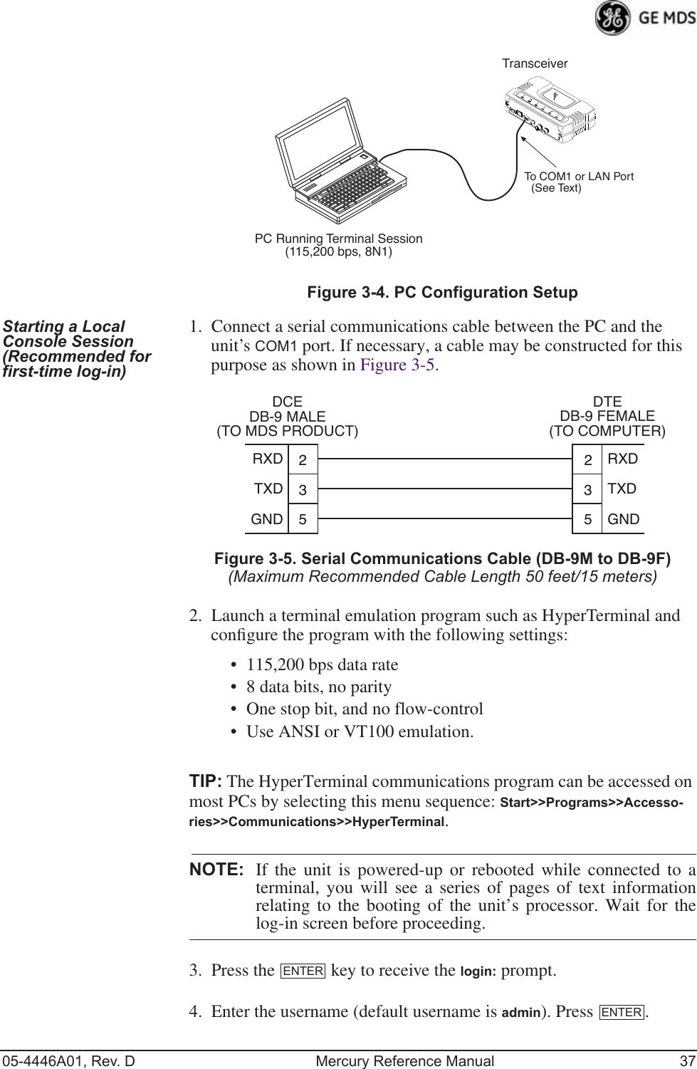
![05-4446A01, Rev. D Mercury Reference Manual 3 1.1 ABOUT THIS MANUAL This Reference Manual is one of two publications provided for users of the Mercury Series TM transceiver system. It contains detailed product information, an overview of common applications, a screen-by-screen review of the menu system, technical specifications, suggested settings for various scenarios, and troubleshooting information. This manual should be available to all personnel responsible for network design, setup, commissioning and troubleshooting of the radios. 1.1.1 Start-Up Guide The Mercury Series Start-Up Guide (Part No. 05-4558A01) is a com-panion publication to the Reference Manual. It is a smaller book, with a specific purpose—to guide an installer in the basic steps for getting a transceiver on the air and communicating with other units in a network. It provides only the essential information installers need for getting their equipment up and running in the shortest time possible. 1.1.2 Online Access to Manuals In addition to printed manuals, many users need access to documents electronically. This is especially useful when you need to access docu-mentation while traveling, or want to share a document with another user in the field. Electronic documents also allow searching for a spe-cific term or subject, especially in larger manuals.Access manuals for our equipment anytime from our Web site at www.GEmds.com . Simply click the Downloads tab at the top of the home page and select Product Manuals from the drop-down list. A search window appears to help you locate the manual you need.Online manuals are provided as PDF files in the Adobe ® Acrobat ® stan-dard. If necessary, download the free reader for PDF files from www.adobe.com . 1.1.3 Conventions Used in This Manual On-Screen Menu Items On-screen menu items or command entries are presented in a distinctive font to set them apart from regular text (for example: Network Name, IP Address, Password ). You will find this font most often in Chapter 3, where the menu system is discussed in detail. When variable settings or a range of options are available for a menu option, the items are pre-sented inside brackets, with the default setting (if any) shown last after a semicolon:[ available settings or range; default setting ]](https://usermanual.wiki/GE-MDS/DS-MERCURY900.Users-Manual-Revised-121908-Part-1/User-Guide-1048762-Page-13.png)
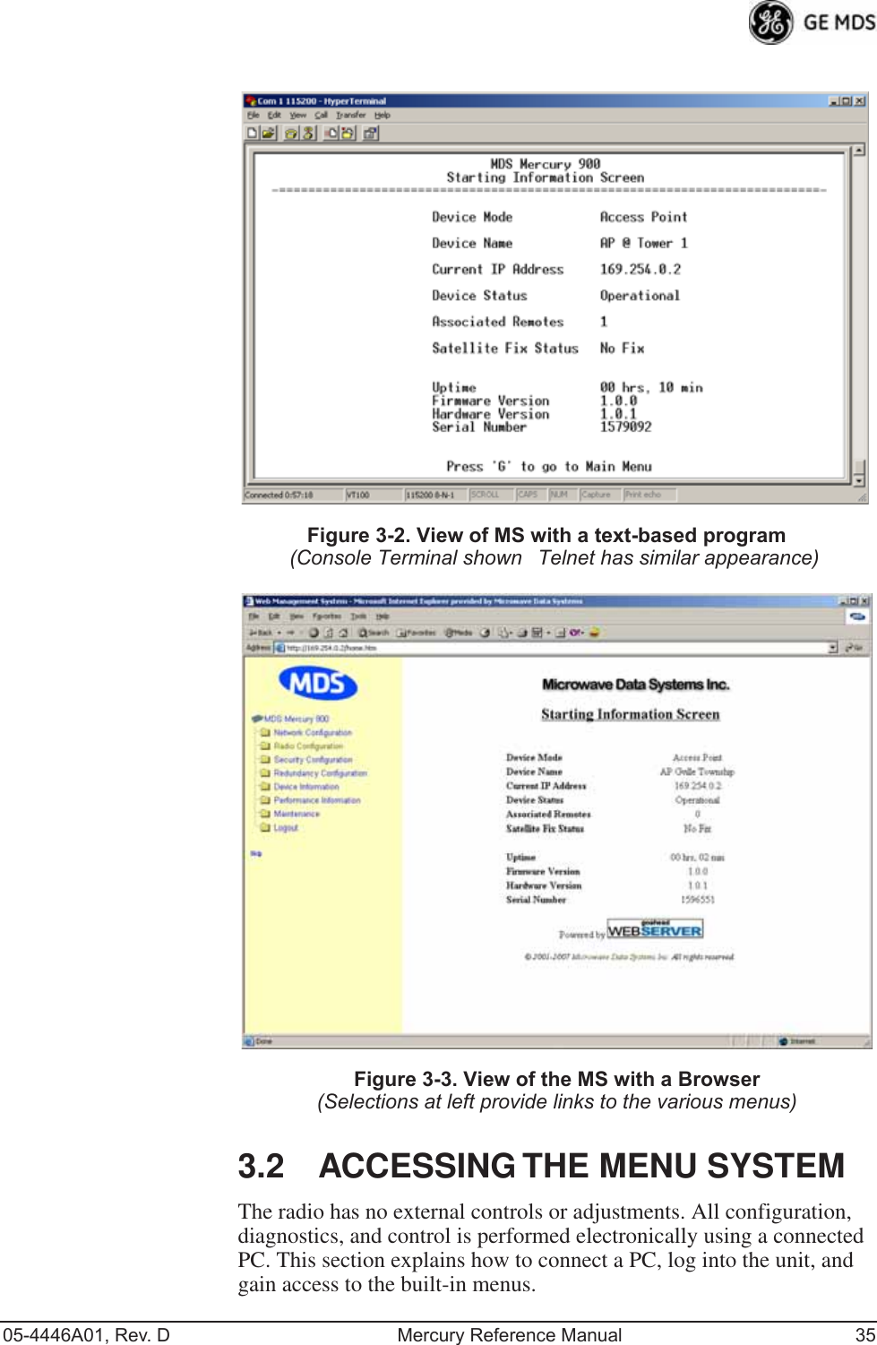
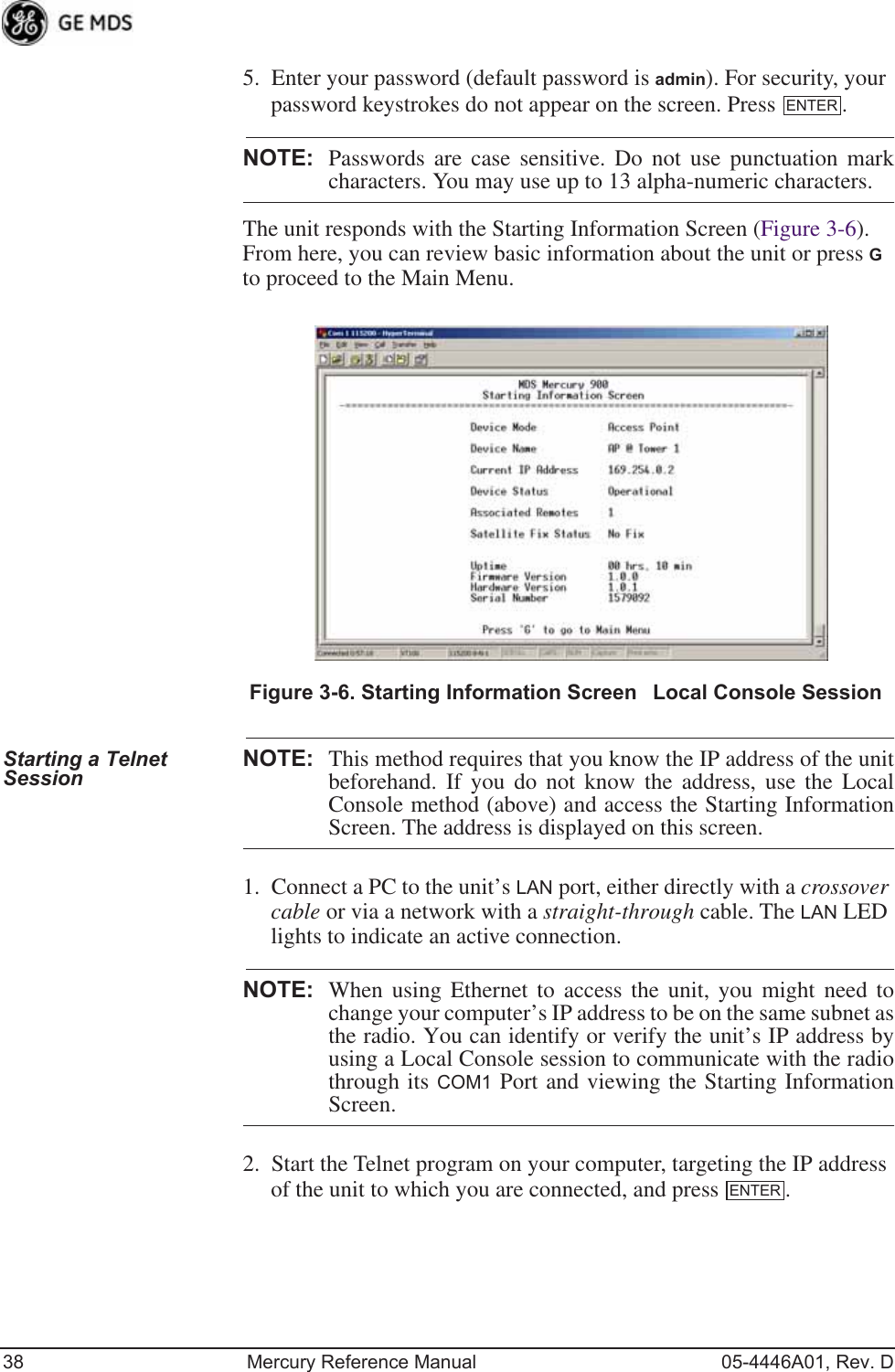
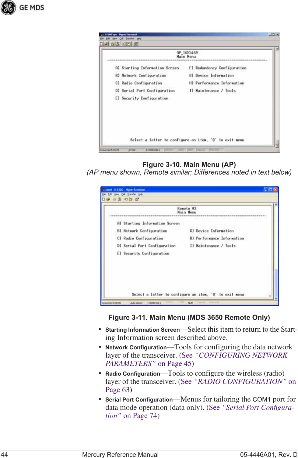
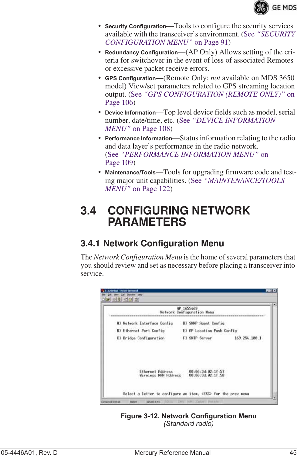
![42 Mercury Reference Manual 05-4446A01, Rev. DNOTE: In the menu descriptions that follow, parameter options/range,and any default values are displayed at the end of the textbetween square brackets. Note that the default setting isalways shown after a semicolon: [available settings or range; default setting]3.3 BASIC OVERVIEW OF OPERATION3.3.1 Starting Information ScreenOnce you have logged into the Management System, the Starting Infor-mation Screen (Figure 3-9) appears with an overview of the transceiver and its current operating conditions. Figure 3-9. Starting Information Screen(AP screen shown; Remote similar, differences noted below)•Device Mode—Operating mode of the unit as it relates to the radio network.•Device Name—This is a user-defined parameter that appears in the heading of all pages. (To change it, see Network Configura-tion Menu on Page 45.)•Current IP Address—Unit’s IP address [169.254.0.2]•Device Status—Condition of the unit’s operation as follows:At Access Point:•Operational—Unit operating normally.•Initializing—This is the first phase after boot-up.•Synchronizing—Unit is waiting for the GPS receiver to obtain a satellite fix and for its internal clock to synchronize to the GPS timing signals.](https://usermanual.wiki/GE-MDS/DS-MERCURY900.Users-Manual-Revised-121908-Part-1/User-Guide-1048762-Page-52.png)
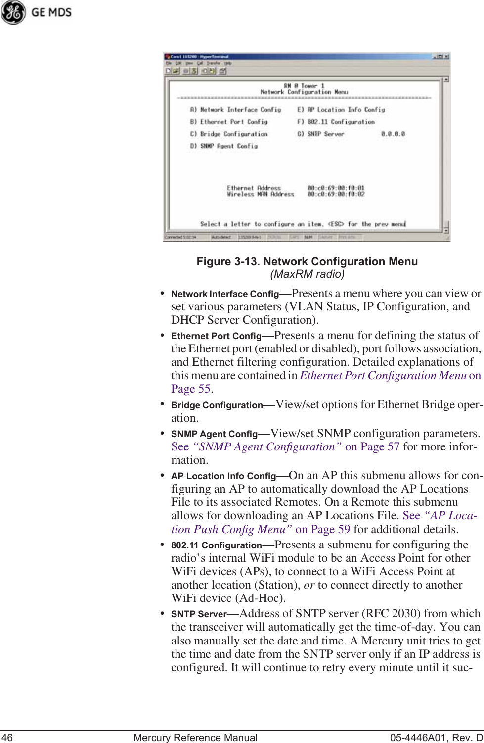
![05-4446A01, Rev. D Mercury Reference Manual 47ceeds. The transceivers use UTC (Universal Time Coordinated) with a configurable time offset. [0]NOTE: The Mercury gets time of day data from the GPS receiver if thereceiver gets a satellite fix.Network Interface Configuration SubmenuInvisible place holderFigure 3-14. Network Interface Configuration Submenu•VLAN Status—This selection is used to enable or disable virtual LAN operation. For details, refer to VLAN Configuration Menu on Page 47. [enable, disabled; disabled]•IP Configuration—This selection presents a submenu for config-uring the local IP address of the transceiver. Detailed explana-tions are provided in the section titled IP Configuration Menu on Page 53.•DHCP Server Config—Menu for configuration of DHCP services by the Access Point. DHCP provides “on-the-fly” IP address assignments to other LAN devices, including Mercury Series units. For details, refer to DHCP Server Configuration (Data and Mgmt) on Page 50.VLAN Configuration MenuThe VLAN Configuration menu (Figure 3-15) becomes active and vis-ible when you enable VLAN Status on the Network Interface Configura-tion Menu, and you press the Enter key.CAUTION:The VLAN Status parameter must be consistent at both theAccess Point and Remote radios in order for data to flowcorrectly. Failure to do so might result in data not being trans-ported correctly even when the radios are in an associated stateand able to communicate over-the-air.](https://usermanual.wiki/GE-MDS/DS-MERCURY900.Users-Manual-Revised-121908-Part-1/User-Guide-1048762-Page-57.png)
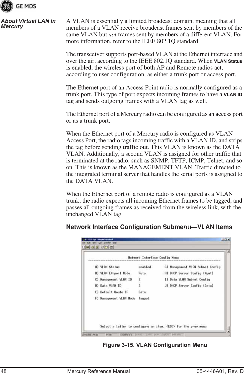
![05-4446A01, Rev. D Mercury Reference Manual 49•VLAN Status—Defines whether the radio handles Ethernet frames in “extended” 802.1Q mode or in “normal” mode in the Ethernet port. If configured with a trunk port, the Mercury passes all tagged traffic regardless of the VLAN ID. The Mer-cury only uses the Data VLAN ID parameter when the ETH port is configured as an Access Port.[enabled, disabled; disabled]•VLAN Ethport Mode—Defines if the Ethernet port acts as a trunk port or as an access port. Auto mode defines the port as a trunk port in an AP, or an access port in a Remote radio. [Auto, Trunk, Access; Auto]•Management VLAN ID—Defines the VLAN ID for traffic directed to the radio itself, other than the terminal server process. This VLAN ID is used for filtering and for tagging purposes. [1-4094; 2]•Data VLAN ID—Defines the VLAN ID assigned to traffic directed to and from the Ethernet port and the terminal server process in the radio. This VLAN ID is used for filtering and tagging pur-poses. [1-4094; 3]•Default Route IF—Defines the VLAN that contains the default gateway in the radio. [MGMT, DATA; MGMT]•Management VLAN Mode—Applies the VLAN tag to management frames. [Tagged, Native; Tagged].•Management VLAN Subnet Config—Presents a screen where you can set the IP Address Mode, Static IP Address, and Static IP Netmask (see Figure 3-16 on Page 50).•DHCP Server Config (Mgmt)—Presents a screen where you can view or set the DHCP server status and address information for management functions (see Figure 3-17 on Page 51).•Data VLAN Subnet Config—Presents a screen where you can view or set the IP mode and address information (see Figure 3-19 on Page 52).•DHCP Server Config (Data)—Presents a screen where you can view or set DHCP server status and address information for data functions (see Figure 3-18 on Page 52).](https://usermanual.wiki/GE-MDS/DS-MERCURY900.Users-Manual-Revised-121908-Part-1/User-Guide-1048762-Page-59.png)
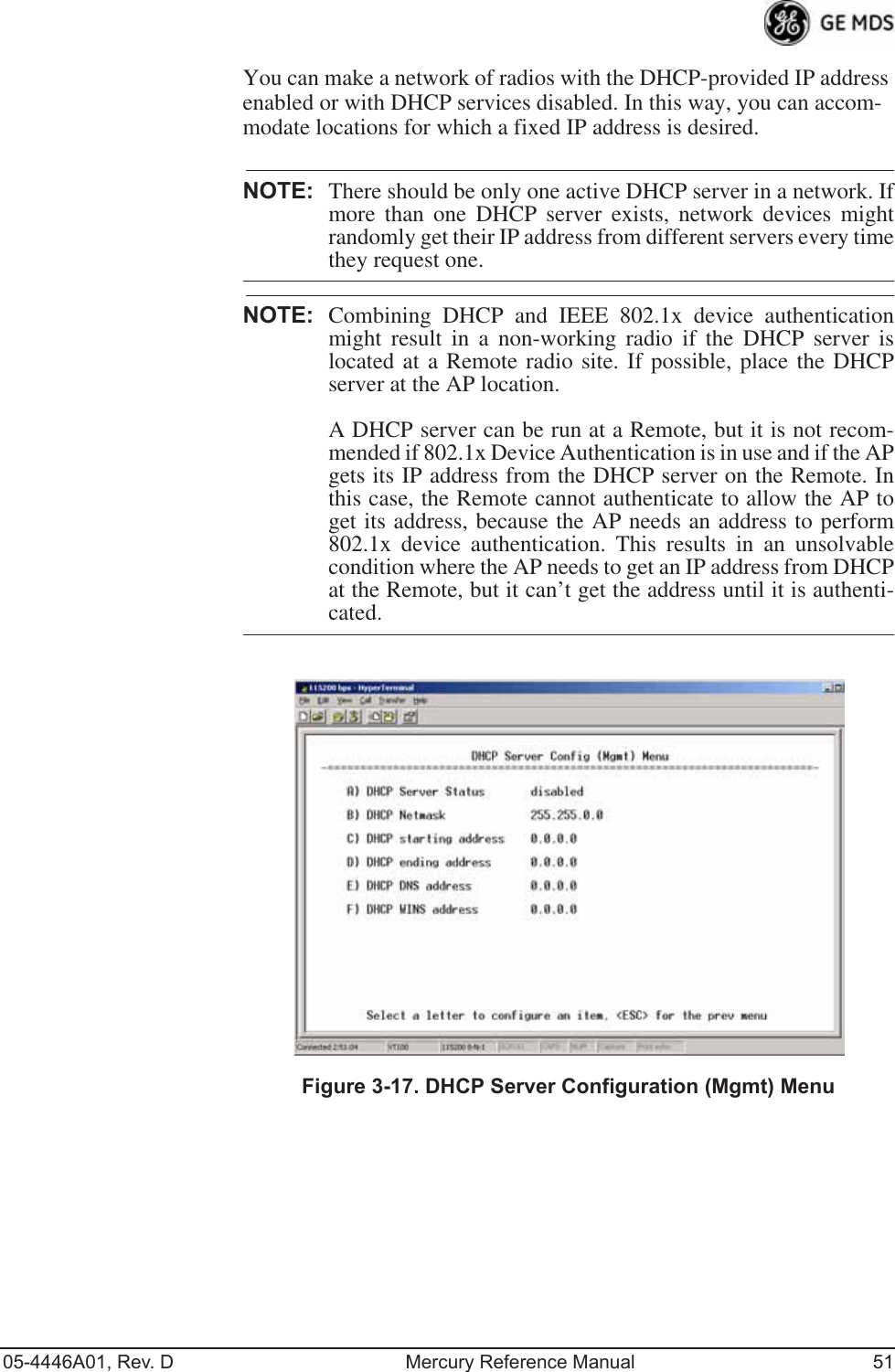
![50 Mercury Reference Manual 05-4446A01, Rev. DManagement VLAN Subnet Configuration MenuInvisible place holderFigure 3-16. Management VLAN Subnet Configuration MenuNOTE: Changes to any of the following parameters while communi-cating over the network (LAN or over-the-air) might cause aloss of communication with the unit you are configuring. Youmust re-establish communication using the new IP address.•IP Address Mode—Defines the source of the IP address of this device. Only static IP addressing mode is available when VLAN Status is enabled. [Static, Dynamic; Static]•Static IP Address—The IPv4 local IP address. [192.168.1.1]•Static IP Netmask—The IPv4 local subnet mask. This value is used when the radio attempts to send a locally initiated message, either from the terminal server, or from a management process. [255.255.0.0]The lower three lines of the screen (Current IP Address, Current IP Netmask, Current IP Gateway) show the current addressing configured at the trans-ceiver. Current IP Gateway only displays on this screen if Default Route IF on the Network Interface Config menu (Figure 3-15 on Page 48) is set to Management.Selecting option I from the menu in Figure 3-15 on Page 48 displays the screen shown in Figure 3-19 on Page 52. Note that the IP address is dif-ferent even though it is the same physical unit. This is because this IP address is defined for a different VLAN.DHCP Server Configuration (Data and Mgmt)A transceiver can provide automatic IP address assignments to other IP devices in the network by providing DHCP (Dynamic Host Configura-tion Protocol) services. This service eliminates setting an individual device IP address on Remotes in the network, but it requires some plan-ning of the IP address range. One drawback to network-wide automatic IP address assignments is that SNMP services might become inacces-sible as they are dependent on fixed IP addresses.](https://usermanual.wiki/GE-MDS/DS-MERCURY900.Users-Manual-Revised-121908-Part-1/User-Guide-1048762-Page-60.png)
![52 Mercury Reference Manual 05-4446A01, Rev. DInvisible place holderFigure 3-18. DHCP Server Configuration (Data) Menu•DHCP Server Status—Enable/Disable the response to DHCP requests to assign an IP address. [Disabled/Enabled; Disabled]•DHCP Netmask—IP netmask to be assigned along with the IP address in response to a DHCP request. [0.0.0.0]•DHCP starting address—Lowest IP address in the range of addresses provided by this device. [0.0.0.0]•DHCP ending address—Highest IP address in the range of addresses provided by this device. A maximum of 256 addresses is allowed in this range. [0.0.0.0]•DHCP DNS address—Domain Name Server address provided by this service.•DHCP WINS address—Windows Internet Naming Service server address provided by this service.Data VLAN Subnet Configuration Menu Invisible place holderFigure 3-19. Data VLAN Subnet Configuration Menu](https://usermanual.wiki/GE-MDS/DS-MERCURY900.Users-Manual-Revised-121908-Part-1/User-Guide-1048762-Page-62.png)
![05-4446A01, Rev. D Mercury Reference Manual 53•IP Address Mode—Defines the source of this device’s IP address. Only static IP addressing mode is available when VLAN Status is enabled [Static; Static]•IP Address—The IPv4 local IP address. [192.168.1.1]•IP Netmask—The IPv4 local subnet mask. This value is used when the radio attempts to send a locally initiated message, from either the terminal server or the management process. [255.255.0.0]•IP Gateway—The IPv4 address of the default gateway device, typically a router. [0.0.0.0]The lower three lines of the screen (Current IP Address, Current IP Netmask, and Current IP Gateway) show the current addressing configured at the transceiver. Current IP Gateway only displays on this screen if Default Route IF on the Network Interface Config menu (Figure 3-15 on Page 48) is set to Data.Invisible place holderIP Configuration MenuFigure 3-20. IP Configuration MenuCAUTION: Changes to the following parameters while communicatingover the network (LAN or over-the-air) might cause a loss ofcommunication with the unit being configured. You mustre-establish communication using the new IP address.•IP Address Mode—Defines the source of this device’s IP address. [Static, Dynamic; Static]•Static IP Address (User Review Recommended)—Essential for con-nectivity to the transceiver’s MS using the LAN port. Enter any valid IP address that is unique within the network. This field is unnecessary if DHCP is enabled. [192.168.1.1]•Static IP Netmask—The IPv4 local subnet mask. This field is unnecessary if DHCP is enabled. [255.255.0.0]](https://usermanual.wiki/GE-MDS/DS-MERCURY900.Users-Manual-Revised-121908-Part-1/User-Guide-1048762-Page-63.png)
![54 Mercury Reference Manual 05-4446A01, Rev. D•Static IP Gateway—The IPv4 address of the network gateway device, typically a router. This field is unnecessary if DHCP is enabled. [0.0.0.0]The lower three items on the screen (Current IP Address, Net-mask and Gateway) show the actual addressing at the trans-ceiver whether it was obtained from static configuration or from a DHCP server.802.11 Configuration Submenu Invisible place holderFigure 3-21. 802.11 Configuration Submenu•802.11 Mode—Configures the WiFi radio to be an Access Point for other WiFi devices (AP), to connect to a WiFi Access Point at another location (Station), or to connect directly to another WiFi device (Ad-Hoc).•SSID—Service Set Identifier, the name of the wireless LAN to which to connect. This is equivalent to Network Name in GE MDS terminology.•Station Channel—Sets the 802.11 channel the device will use. This can only be set to Auto when in Station mode.•WEP Status—The type of WEP encryption being used, if any.•WEP Passphrase—The Passphrase used in WEP encryption.•WEP Key—The key used in WEP encryption. This key should be entered in hexadecimal format preceded by 0x. The key should be 13 or 26 hexadecimal characters. For example, 0x1a2b3c4d5e6f709a8b7c6d5e4f.•NIC in Bridge—When enabled, the WiFi interface is added to the network bridge, allowing traffic to pass between the WiFi and the other interfaces (LAN and wireless).](https://usermanual.wiki/GE-MDS/DS-MERCURY900.Users-Manual-Revised-121908-Part-1/User-Guide-1048762-Page-64.png)
![05-4446A01, Rev. D Mercury Reference Manual 553.4.2 Ethernet Port Configuration MenuThe transceiver allows for special control of the Ethernet interface, to allow traffic awareness and availability of the backhaul network for redundancy purposes.NOTE: The transceiver’s network port supports 10BaseT and100BaseT connections. Confirm that your hub/switch iscapable of auto-switching data rates.To prevent excessive Ethernet traffic from degrading perfor-mance, place the transceiver in a segment, or behind routers.Invisible place holderFigure 3-22. Ethernet Port Configuration Menu(MaxRM radio)•Ethernet Port Enable—Allows enabling/disabling Ethernet traffic for security purposes. Setting it to enabled enables the port. [enabled, disabled; enabled]•Ethernet Port Phy Rate—The Ethernet port’s configured speed.•Eth Port Follows Association (Remote Only)—When enabled, the Ethernet port is disabled until the Remote associates. This allows a PC or laptop connected to the Remote to know when the wireless link is available. This feature helps middleware on the laptop in making connectivity decisions. In addition, if the Remote moves between Access Points on different subnets, then the laptop can DHCP for a new address when the link comes back up. [enabled, disabled; disabled]•Ethernet Filtering Config—Allows enabling/disabling filtering and specifying of Ethernet addresses.](https://usermanual.wiki/GE-MDS/DS-MERCURY900.Users-Manual-Revised-121908-Part-1/User-Guide-1048762-Page-65.png)
![56 Mercury Reference Manual 05-4446A01, Rev. DEthernet Filtering Configuration MenuInvisible place holderFigure 3-23. Ethernet Filtering Configuration Menu•Enable Filtering—Activates Ethernet filtering.[enabled, disabled; disabled]•Address 1, 2, 3, 4—Ethernet address fields. When filtering is enabled, the Mercury only accepts traffic on its Ethernet port from the configured addresses. [Valid MAC address string]3.4.3 Bridge Configuration Invisible place holderFigure 3-24. Bridge Configuration Menu•Bridge Priority—View/set the priority of the bridge in the span-ning tree. [0-65535; 32769]•Bridge Hello Time—View/set spanning tree hello time. This parameter affects how often the bridge sends a spanning tree Bridge Protocol Data Unit (BPDU). [1-10 seconds; 2 seconds]](https://usermanual.wiki/GE-MDS/DS-MERCURY900.Users-Manual-Revised-121908-Part-1/User-Guide-1048762-Page-66.png)
![05-4446A01, Rev. D Mercury Reference Manual 57•Bridge Forward Delay—View/set spanning tree forwarding delay. Affects how long the bridge spends listening and learning after initialization. [4-30 seconds; 5 seconds].3.4.4 SNMP Agent ConfigurationThe transceiver contains over 100 custom SNMP-manageable objects as well as the IETF standard RFC1213 for protocol statistics, also known as MIB II. You can use off-the-shelf SNMP managers to access the transceiver’s SNMP Agent’s MIB, such as Castle Rock Computing SNMPc™ and Hewlett Packard OpenView™. The transceiver’s SNMP agent supports SNMPv1, v2, and v3.The objects are split into nine MIB files for use with your SNMP man-ager. There are textual conventions, common files, and specific files. This allows the flexibility to change areas of the MIB and not affect other existing installations or customers.•msdreg.mib—MDS sub-tree registrations•mds_comm.mib—MDS Common MIB definitions for objects and events common to the entire product family•mercury_reg.mib—MDS sub-tree registrations•mercurytrv1.mib—SNMPv1 enterprise-specific traps•mercurytrv2.mib—SNMPv2 enterprise-specific traps•mercury_comm.mib— MIB definitions for objects and events common to the entire Mercury Series•mercury_ap.mib—MIB definitions for objects and events for an Access Point transceiver•mercury_rem.mib—Definitions for objects and events for a Remote radio•mercury_sec.mib—For security management of the radio systemNOTE: SNMP management requires that the proper IP address,network, and gateway addresses are configured in each associ-ated network transceiver. In addition, some management systems might require that youcompile the MIB files in the order shown above.](https://usermanual.wiki/GE-MDS/DS-MERCURY900.Users-Manual-Revised-121908-Part-1/User-Guide-1048762-Page-67.png)
![58 Mercury Reference Manual 05-4446A01, Rev. DInvisible place holderFigure 3-25. SNMP Server Configuration MenuThis menu provides configuration and control of vital SNMP functions.•Read Community String—SNMP community name with SNMPv1/SNMPv2c read access. This string can contain up to 30 alpha-numeric characters.•Write Community String—SNMP community name with SNMPv1/SNMPv2c write access. This string can contain up to 30 alpha-numeric characters.•Trap Community String—SNMP community name with SNMPv1/SNMPv2c trap access. This string can contain up to 30 alpha-numeric characters.•V3 Authentication Password—Authentication password stored in flash memory. This is used when the Agent is managing pass-words locally (or initially for all cases on reboot). This is the SNMPv3 password used for Authentication (currently, only MD5 is supported). This string can contain up to 30 alpha-numeric characters.•V3 Privacy Password—Privacy password stored in flash memory. Used when the SNMP Agent is managing passwords locally (or initially for all cases on reboot). This is the SNMPv3 password used for privacy (DES encryption). This string can contain between 8 and 30 alpha-numeric characters.•SNMP Mode—This specifies the mode of operation of the radio’s SNMP Agent. The choices are: disabled, v1_only, v2_only, v3_only, v1-v2, and v1-v2-v3. If the mode is disabled, the Agent does not respond to any SNMP traffic. If the mode is v1_only, v2_only, or v3_only, the Agent responds only to that version of SNMP traffic. If the mode is v1-v2 or v1-v2-v3, the Agent responds to the specified version of SNMP traffic. [v1-v2-v3]](https://usermanual.wiki/GE-MDS/DS-MERCURY900.Users-Manual-Revised-121908-Part-1/User-Guide-1048762-Page-68.png)
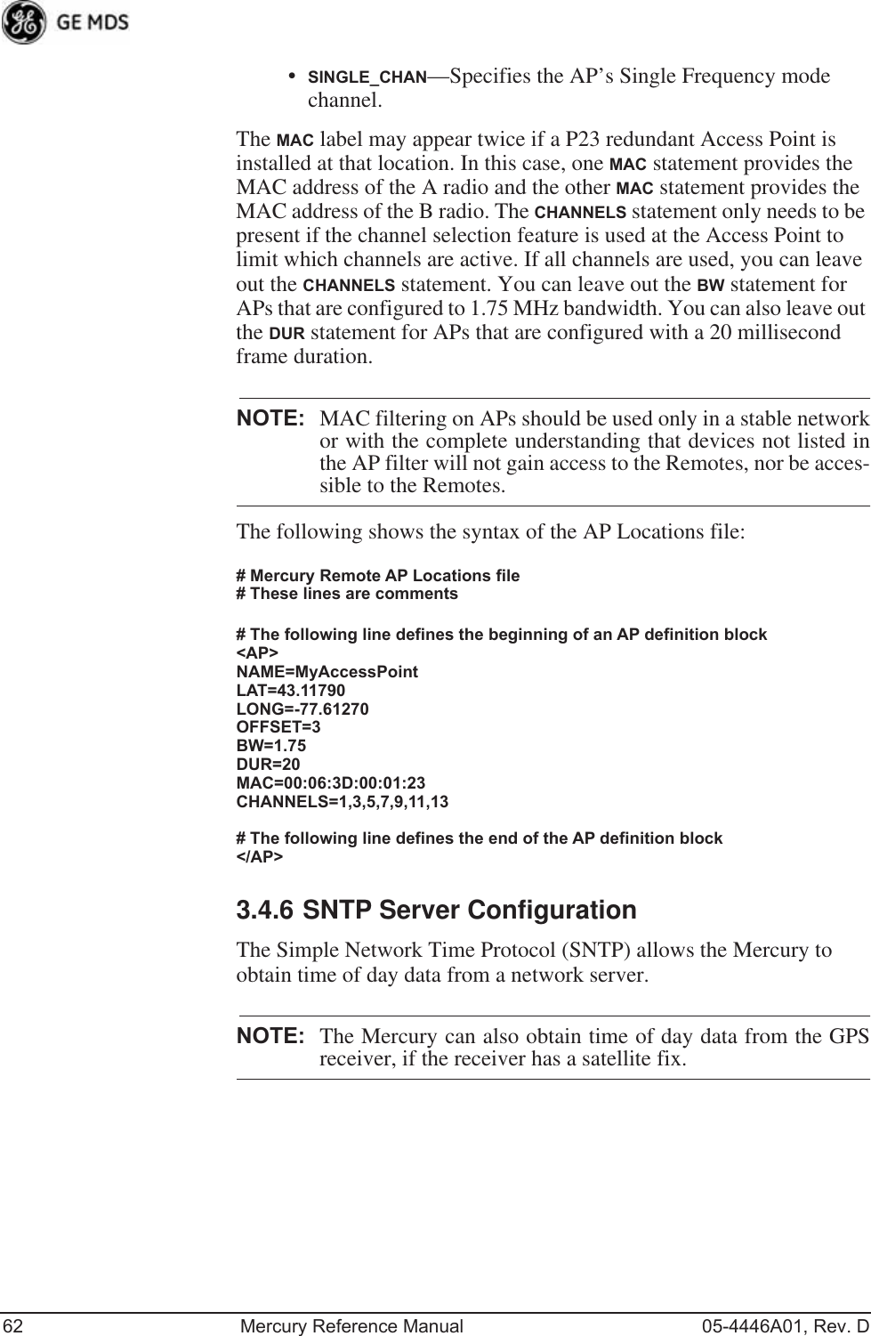
![05-4446A01, Rev. D Mercury Reference Manual 59•Trap Version—This specifies which version of SNMP is used to encode the outgoing traps. The choices are v1_traps, v2_traps, and v3_traps. When v3_traps is selected, v2-style traps are sent, but with a v3 header. [v1_traps, v2_traps, v3_traps]•Auth Traps Status—Indicates whether or not traps are generated for failed authentication of an SNMP PDU. [Disabled/Enabled; Disabled]•SNMP V3 Passwords—Determines whether v3 passwords are managed locally or via an SNMP Manager. The different behav-iors of the Agent, depending on the mode selected, are described in SNMP Mode above.•Trap Manager #1—#4— Table of up to four locations on the net-work to which traps are sent. [Any standard IP address]NOTE: The number in the upper right-hand corner of the screen is theSNMP Agent’s SNMPv3 Engine ID. Some SNMP Managersmay need to know this ID in order interface with the trans-ceiver’s SNMP Agent. The ID only appears on the screenwhen SNMP Mode is either v1-v2-v3 or v3_only.NOTE: For more SNMP information, see “NOTES ON SNMP” onPage 178.3.4.5 AP Location Push Config MenuThis menu configures the AP for updating connected remotes with the AP Locations File loaded on the AP.Invisible place holderFigure 3-26. AP Location Push Config Menu](https://usermanual.wiki/GE-MDS/DS-MERCURY900.Users-Manual-Revised-121908-Part-1/User-Guide-1048762-Page-69.png)
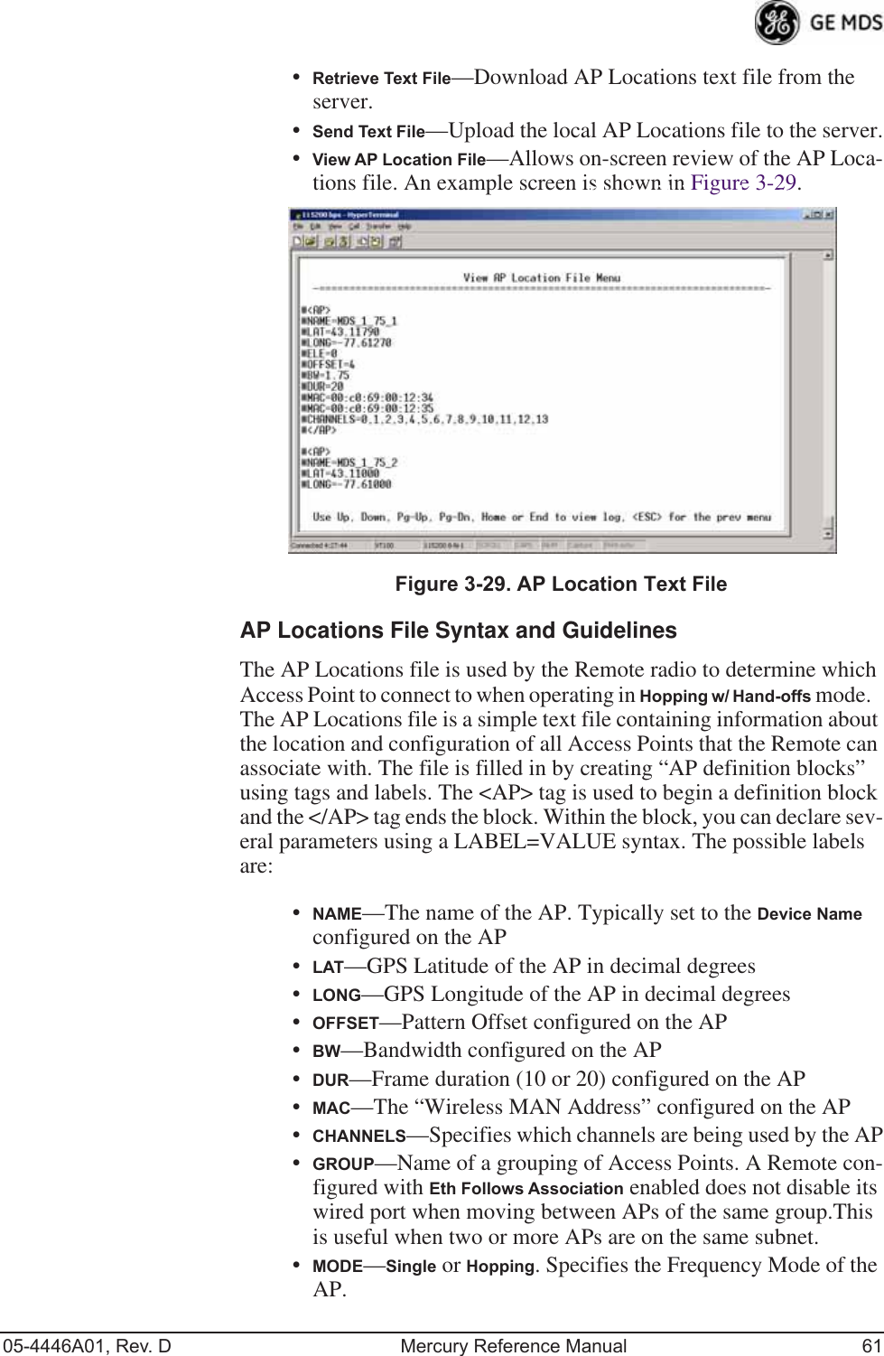
![60 Mercury Reference Manual 05-4446A01, Rev. DInvisible place holderFigure 3-27. AP Location Info Configuration Menu, TFTP Mode(Firmware version 3.0 only)Invisible place holderFigure 3-28. AP Location Info Configuration Menu, USB Mode(Firmware version 3.0 or later)•File Media—A selection of methods for transferring files to and from the radio available on firmware version 3.0 radios. The options are: TFTP and USB.•TFTP Host Address—IP address of the TFTP server that holds the AP locations file. [any valid IP address; 0.0.0.0]•Transfer Options—Menu for configuring the TFTP transfer.•AP Locations Filename—Name of the AP Locations file on the server. [any valid filename string; ap_locations.txt]•Auto AP Location Download—A setting to force connected remotes to download immediately the AP Locations file on the AP. Remotes that associate to an AP with this feature will also download the file.](https://usermanual.wiki/GE-MDS/DS-MERCURY900.Users-Manual-Revised-121908-Part-1/User-Guide-1048762-Page-70.png)
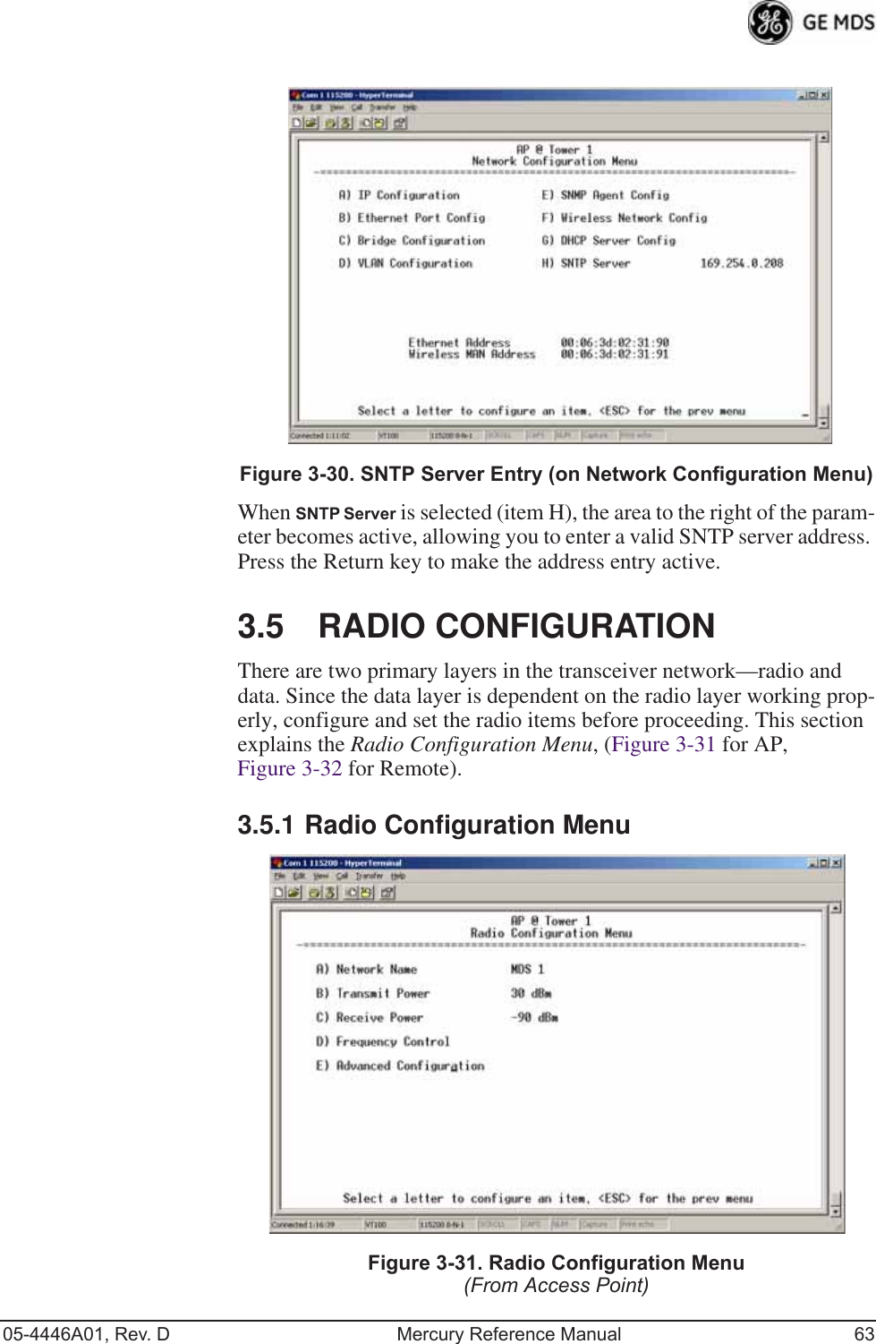
![64 Mercury Reference Manual 05-4446A01, Rev. DFigure 3-32. Radio Configuration Menu(From Remote Unit)Invisible place holderFigure 3-33. Radio Configuration Menu(From Option Set 1 Remote)•Network Name—The user-defined name for the wireless network. [Any 40 character string; MDS-Mercury]•Transmit Power (AP Only)—Sets/displays RF power output level in dBm. This setting should reflect local regulatory limitations and losses in antenna transmission line. (See “How Much Out-put Power Can be Used?” on Page 167 for information on how to calculate this value.) [0—30; 30 (900 model)] [0—23; 23 (3650 model)]](https://usermanual.wiki/GE-MDS/DS-MERCURY900.Users-Manual-Revised-121908-Part-1/User-Guide-1048762-Page-74.png)
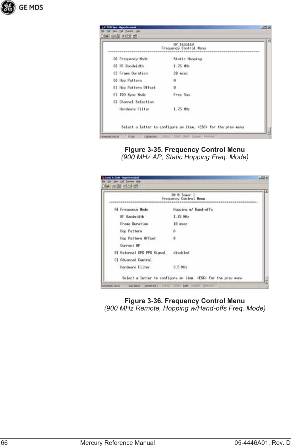
![05-4446A01, Rev. D Mercury Reference Manual 65•Max Transmit Power (Remote Only)—Sets/displays maximum RF power output level in dBm of the Remote. Power level is still controlled by the AP, but it is limited to the maximum level set here. This setting should reflect local regulatory limitations and losses in antenna transmission line. (See “How Much Output Power Can be Used?” on Page 167 for information on how to calculate this value.) [0—30; 30 (900 model) 0—23; 23 (3650 model)•Receive Power (AP Only)—View/set the receiver gain setpoint for the expected strength of incoming signals from Remotes. This setting indicates at what level (in dBm) the AP expects to hear the Remote stations. A setting of -70 would set the AP receiver’s gain to a relatively low level, while a setting of -85 would be a comparatively high gain setting. [-100 to -20; -75]•Frequency Control—Opens a submenu where you can view or set frequency mode bandwidth, channel and other parameters as described in Frequency Control Menu below.•Advanced Configuration—Opens a submenu where you can view or set modulation, protection/hysteresis margins, data compres-sion, ARQ settings, and other parameters as described in Advanced Configuration Menu on Page 72.•Receive Diversity (900 MHz Remote Only)—Allows enabling or disabling the RX2 antenna port for receive operation. The use of two antennas allows “diversity” reception which helps mini-mize the effects of fading due to multipath reception of signals.Frequency Control MenuThe items shown on this menu vary depending on the Frequency Mode Selection (Single Channel, Static Hopping, Hopping w/Hand-offs). Examples of all three screens are provided below, followed by a description of the menu items.Invisible place holderFigure 3-34. Frequency Control Menu(900 MHz AP, Single Channel Freq. Mode)](https://usermanual.wiki/GE-MDS/DS-MERCURY900.Users-Manual-Revised-121908-Part-1/User-Guide-1048762-Page-75.png)