GIL Technology GILBS WiMax Outdoor CPE (N-TYPE) User Manual rev 0415
GIL Technology. CO., Ltd WiMax Outdoor CPE (N-TYPE) rev 0415
UserManual.wiki
>
GIL Technology
>
GILBS User Manual
User manual rev 0415
Navigation menu
Upload a User Manual
Namespaces
Wiki Guide
HTML
PDF
Info
Views
User Manual
Discussion / Help
Navigation
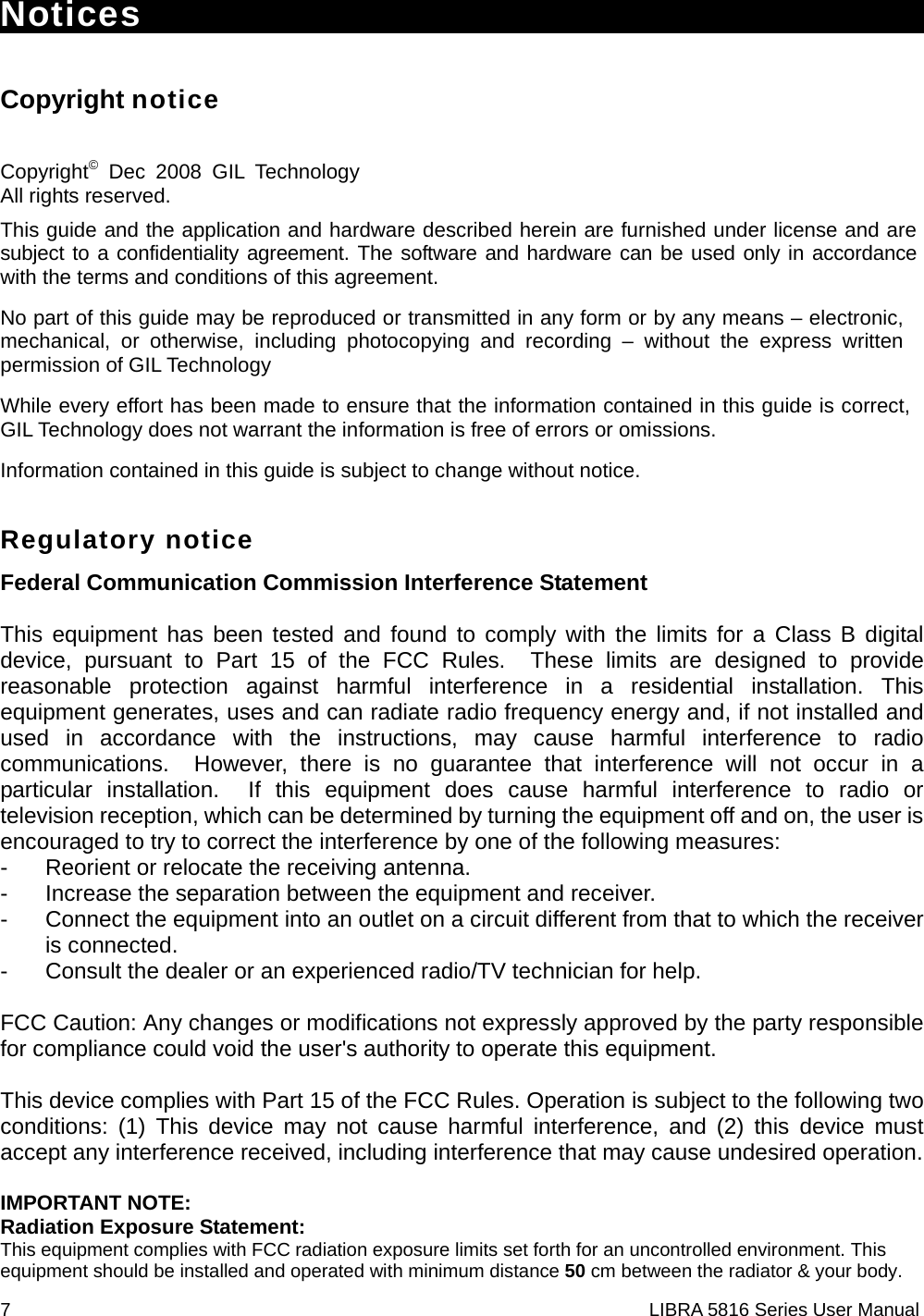
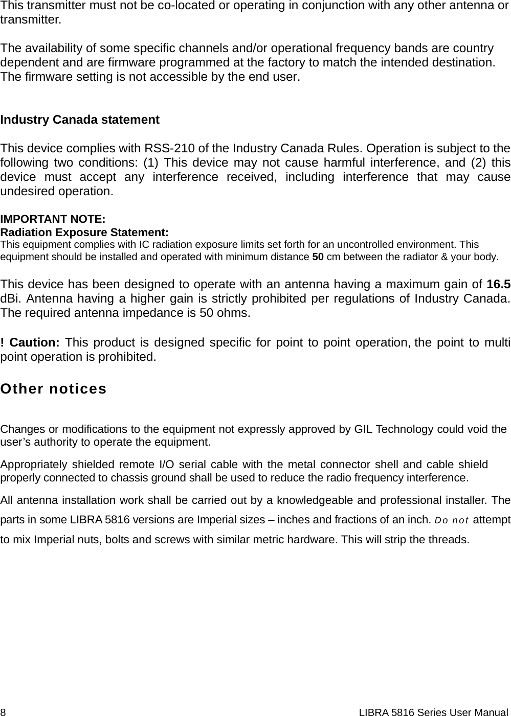
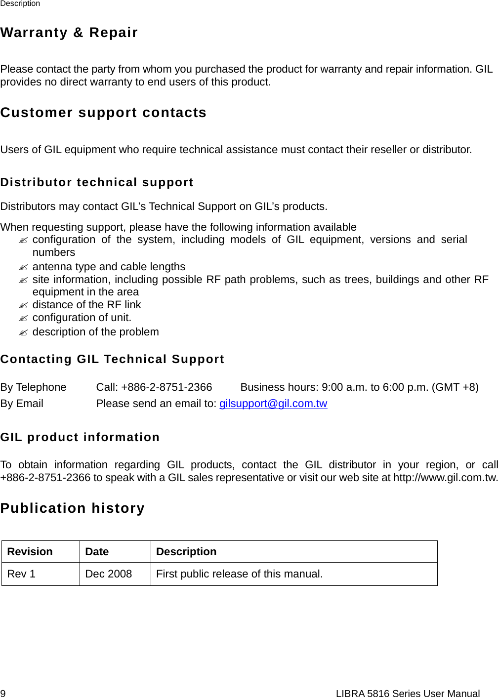
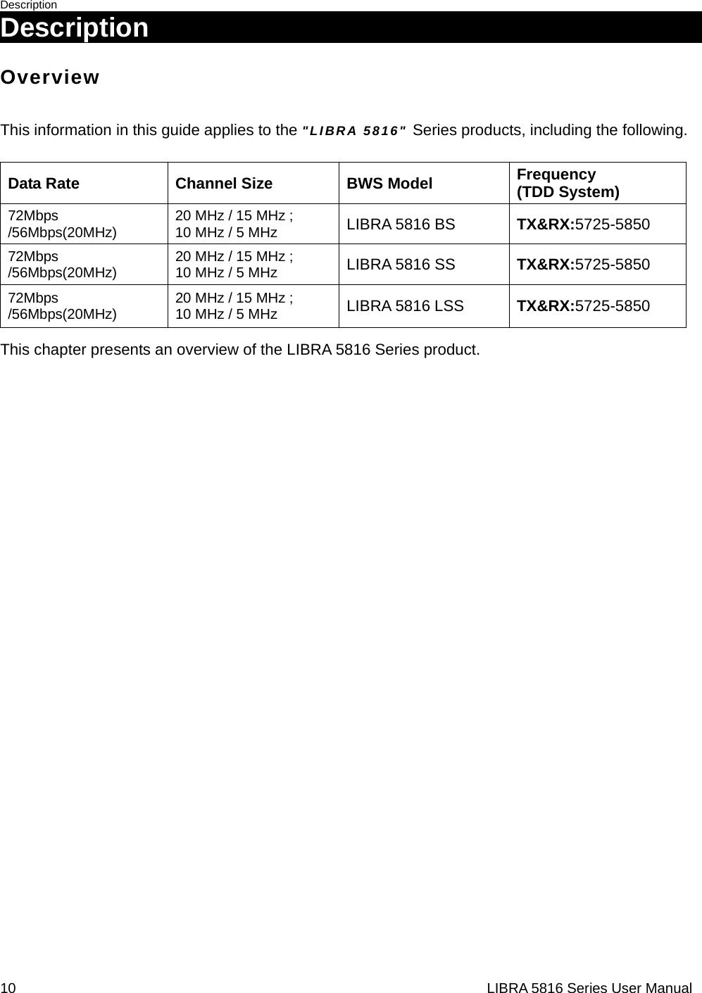
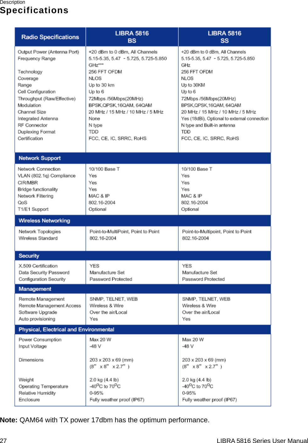
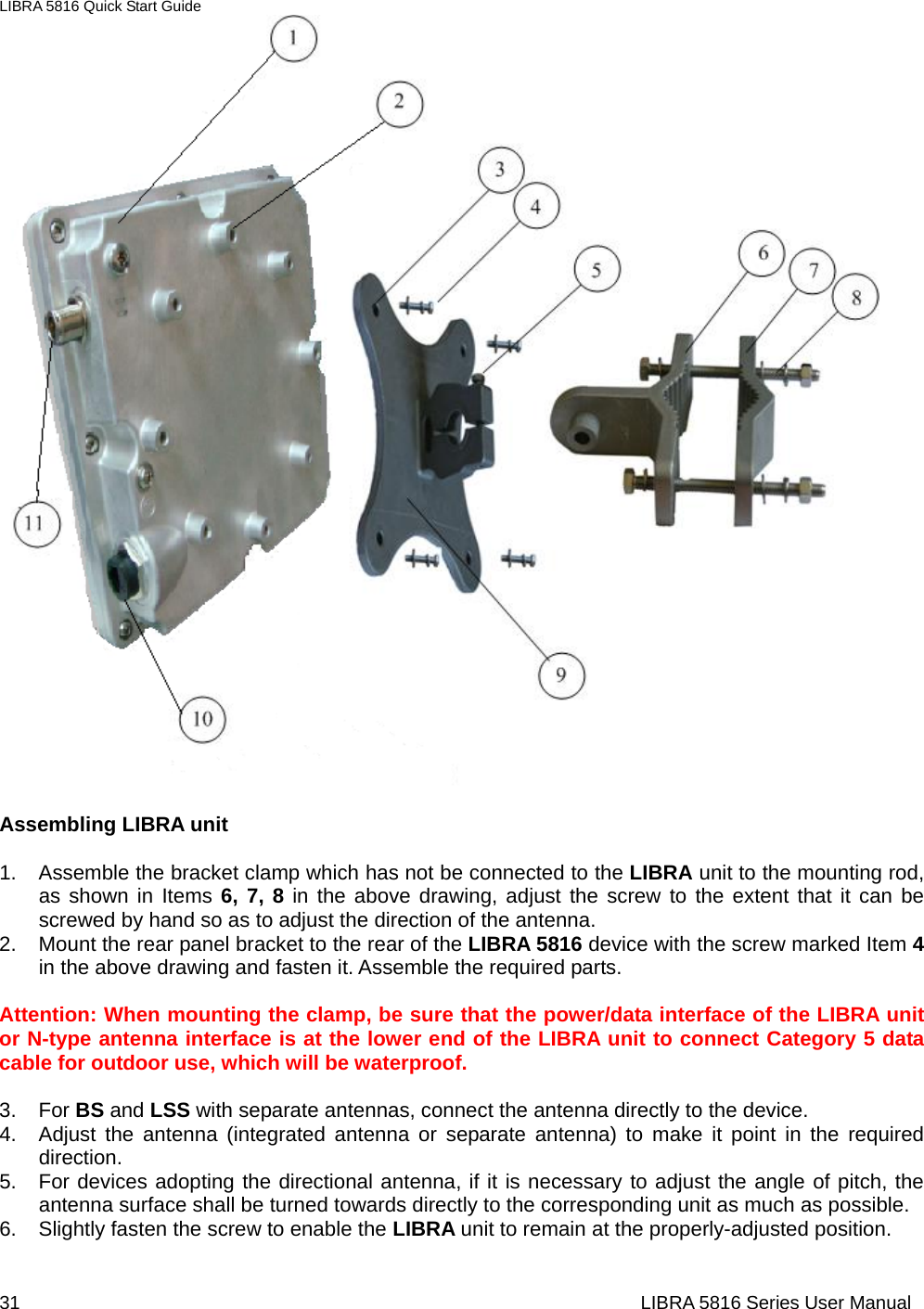
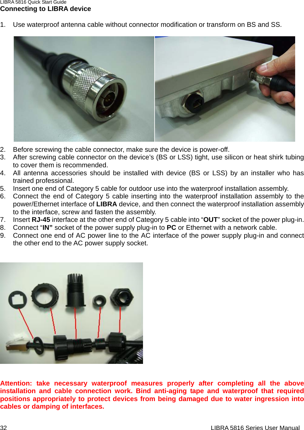
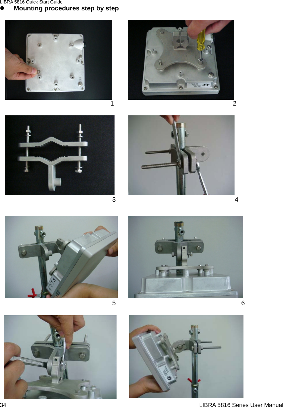
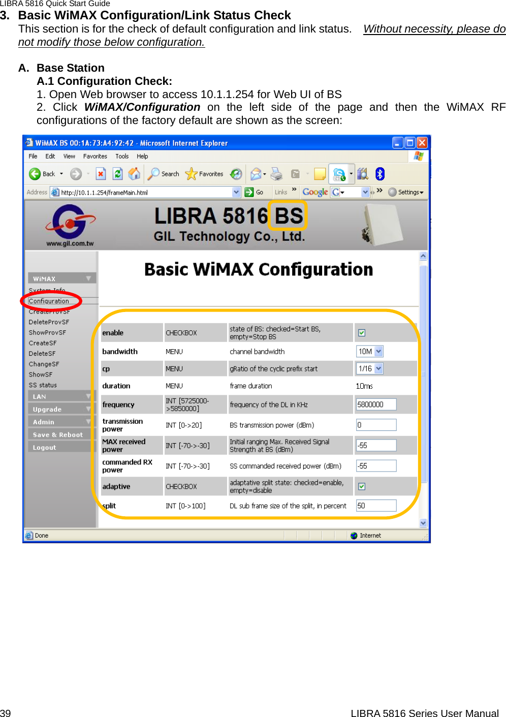
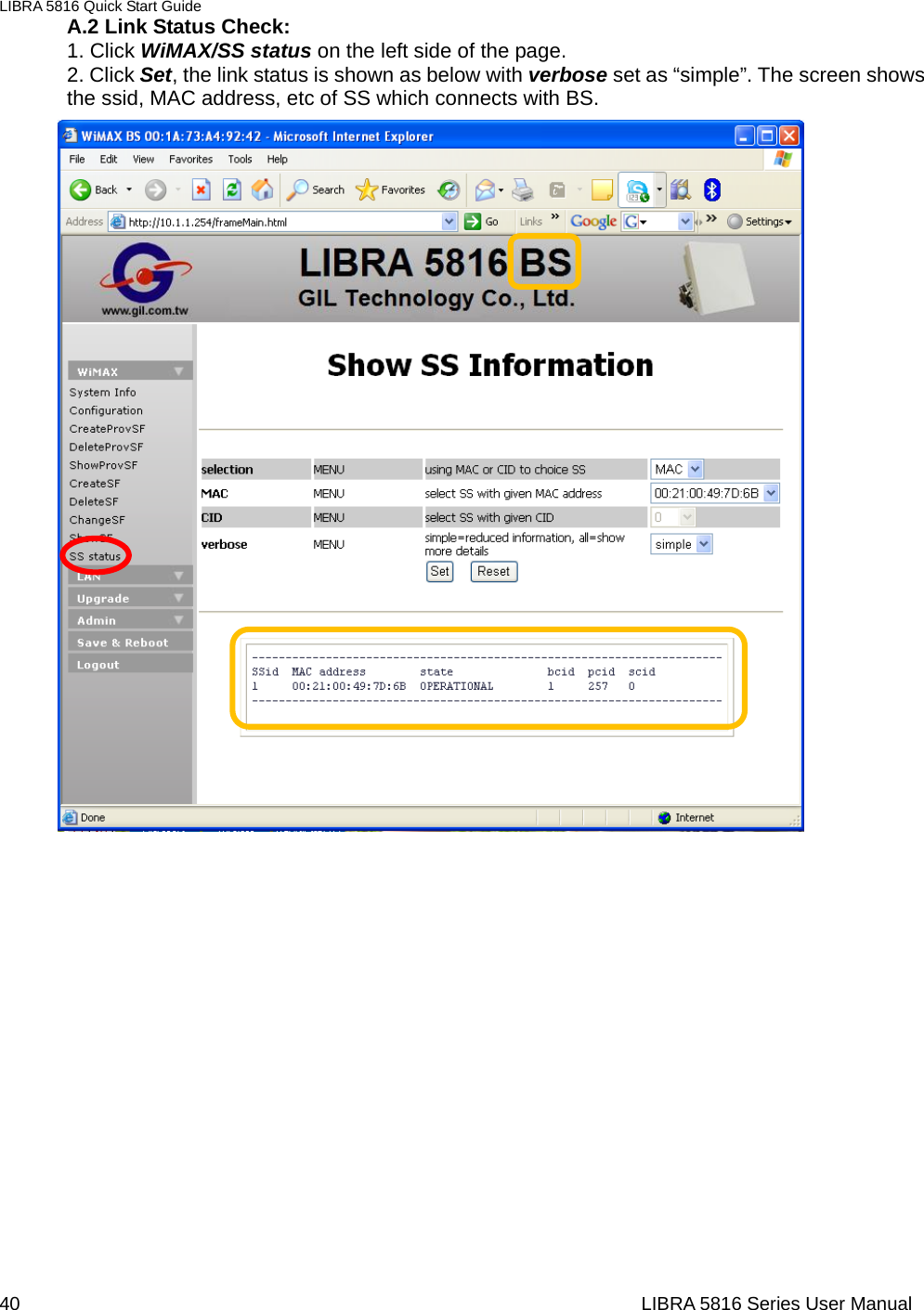
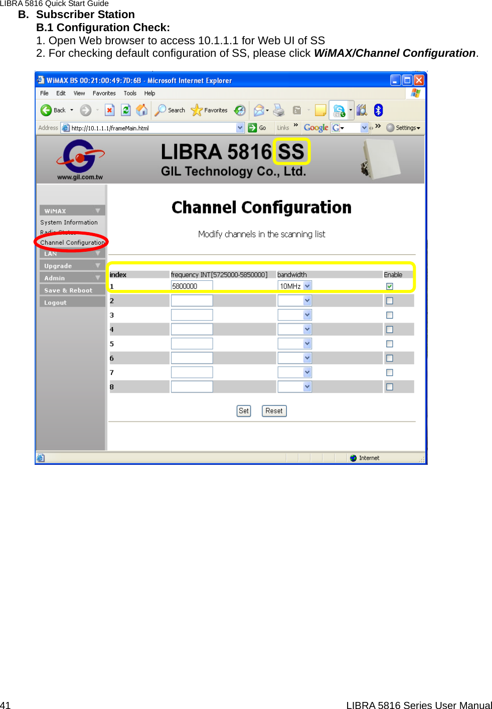
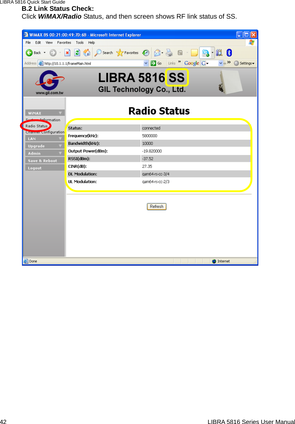
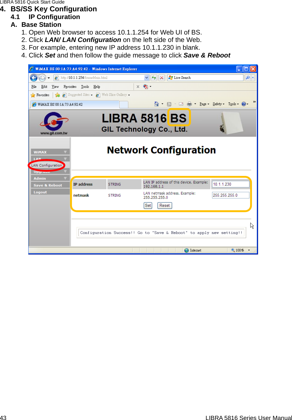
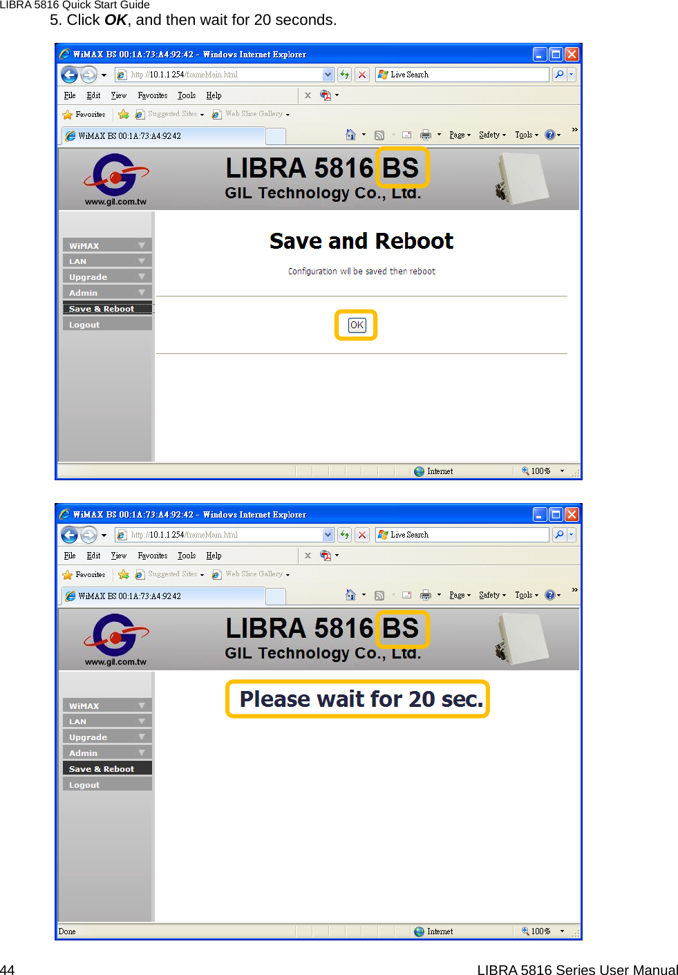
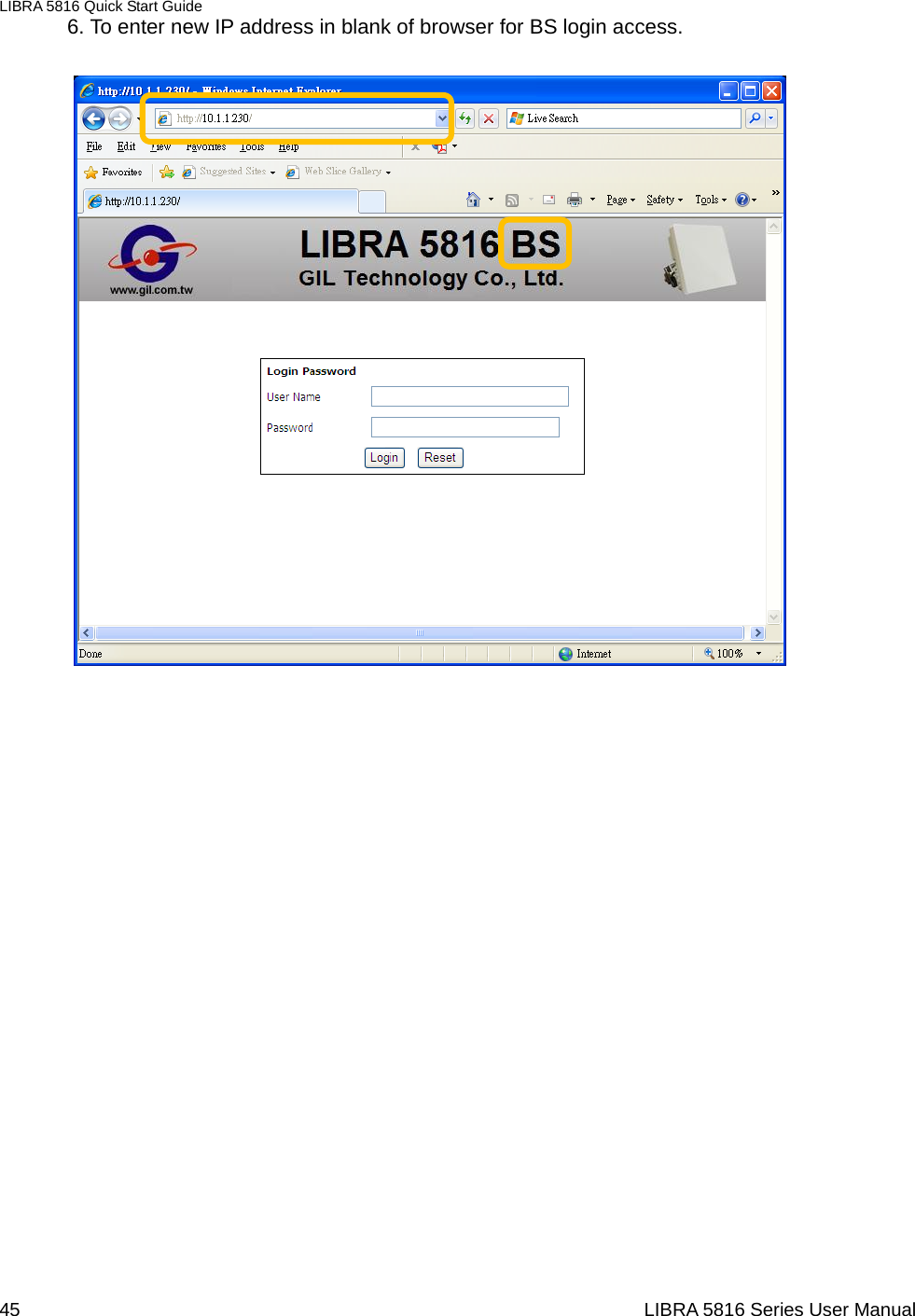
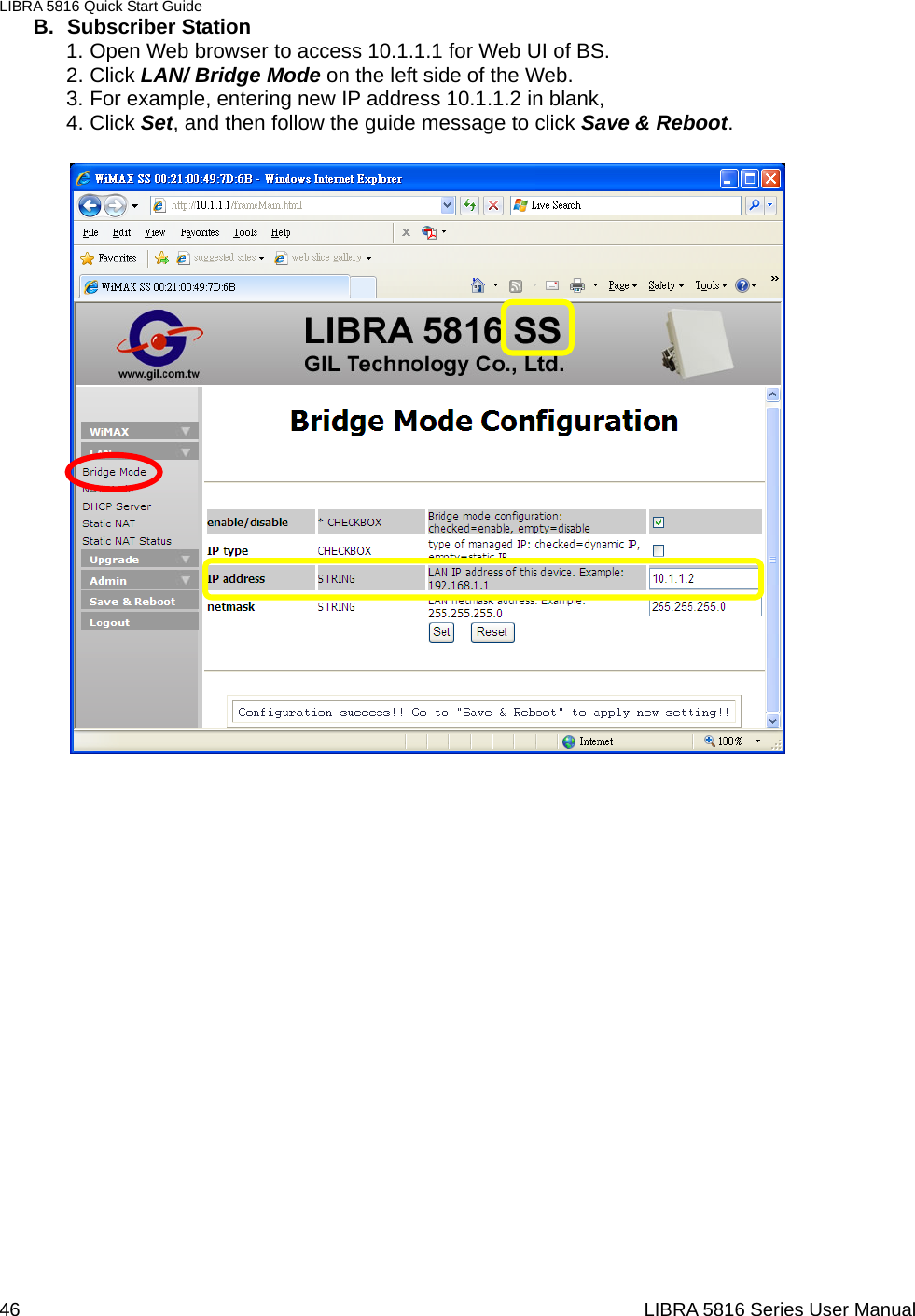
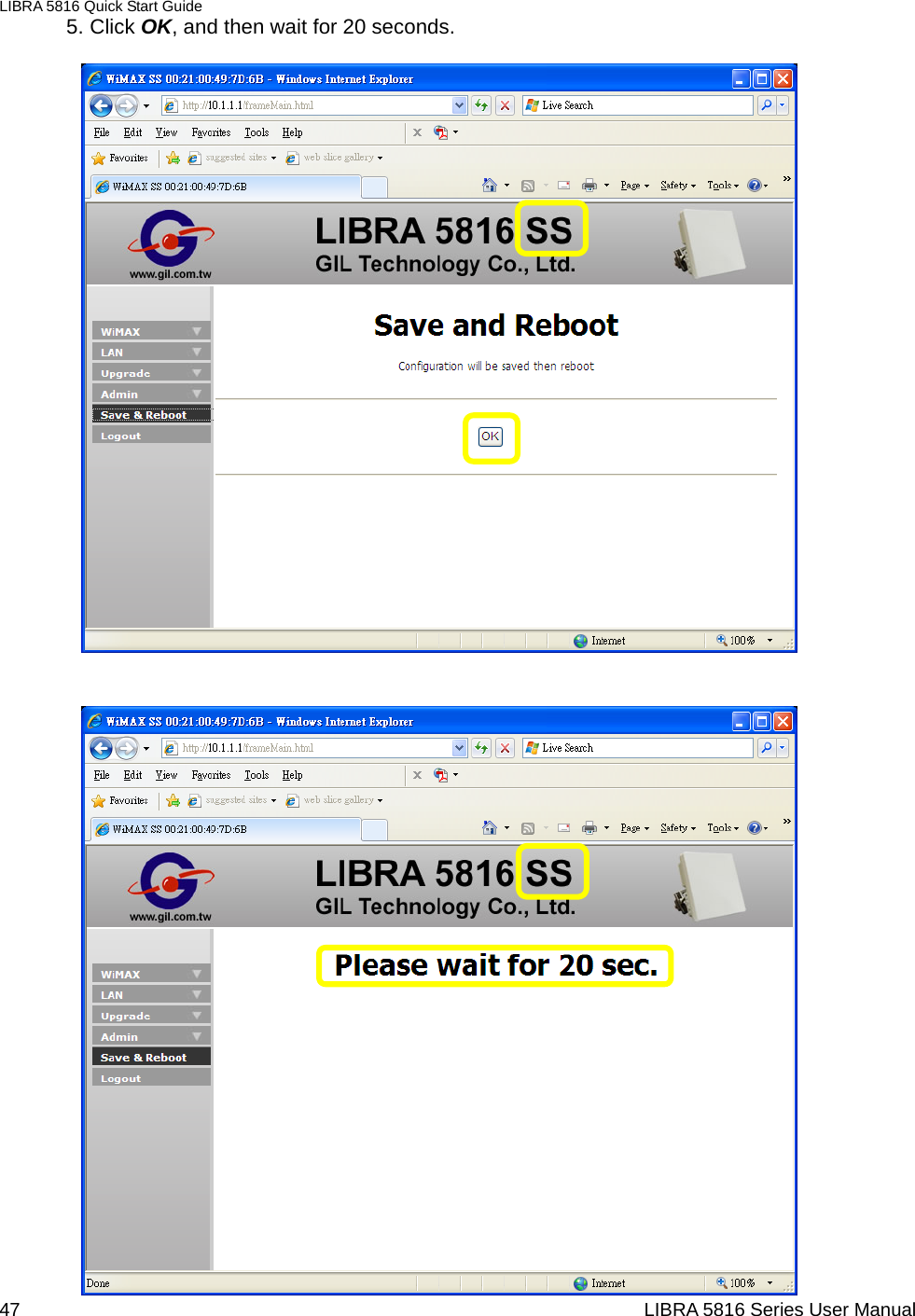
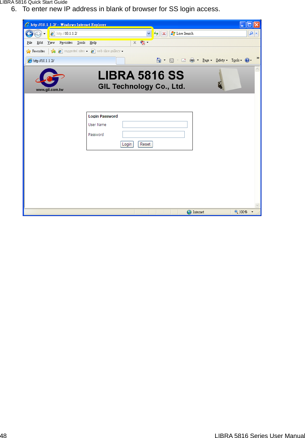
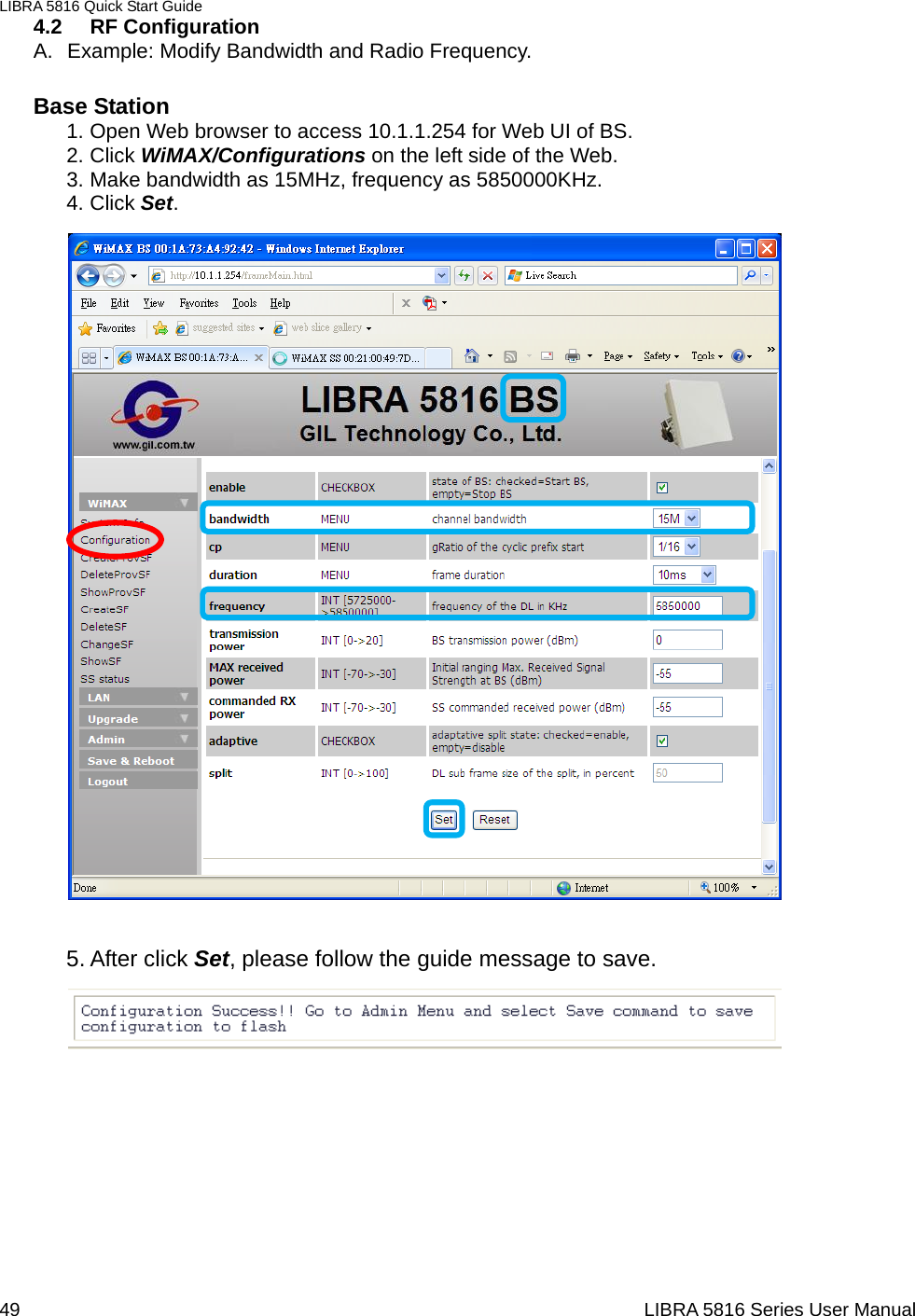
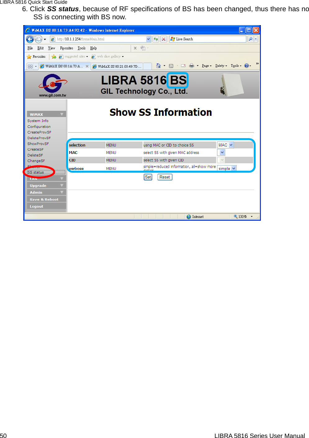
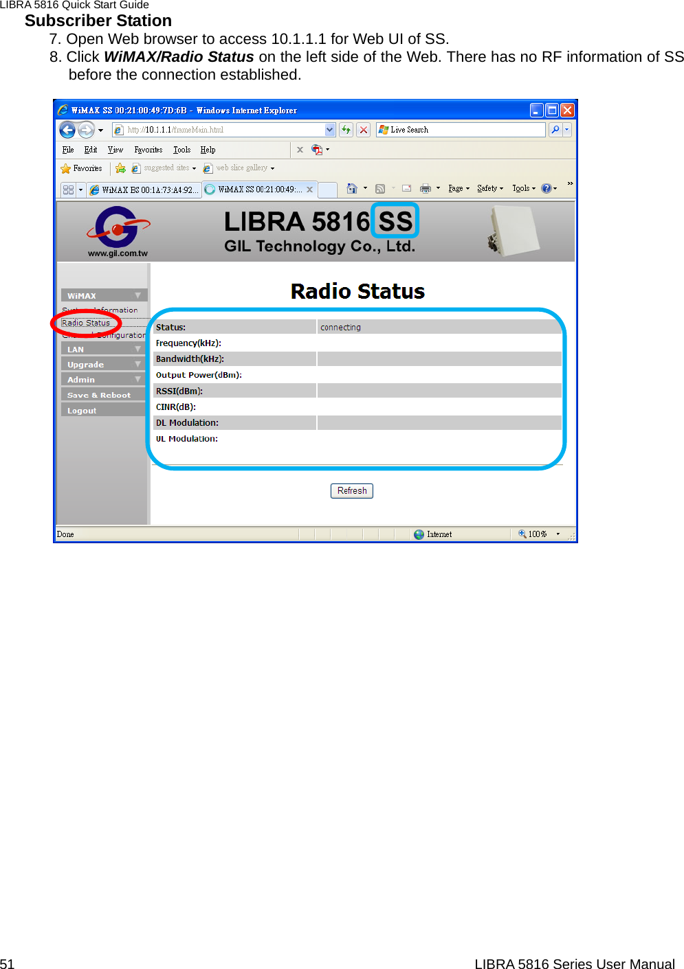
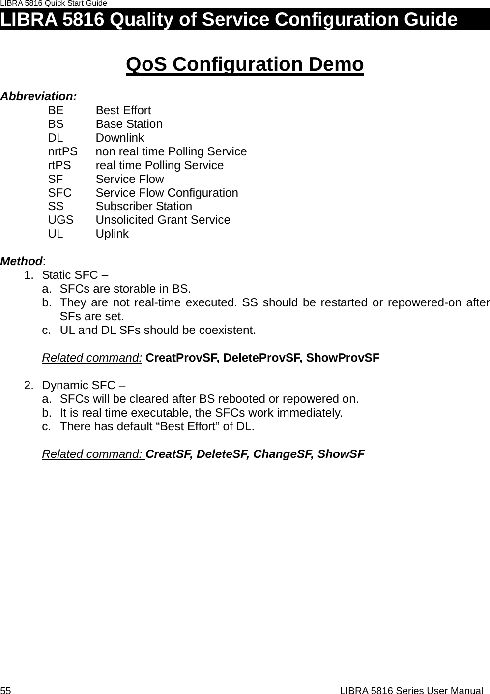
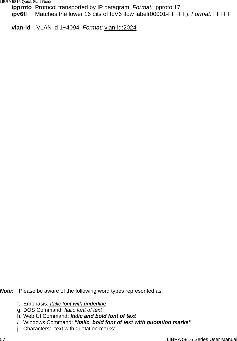
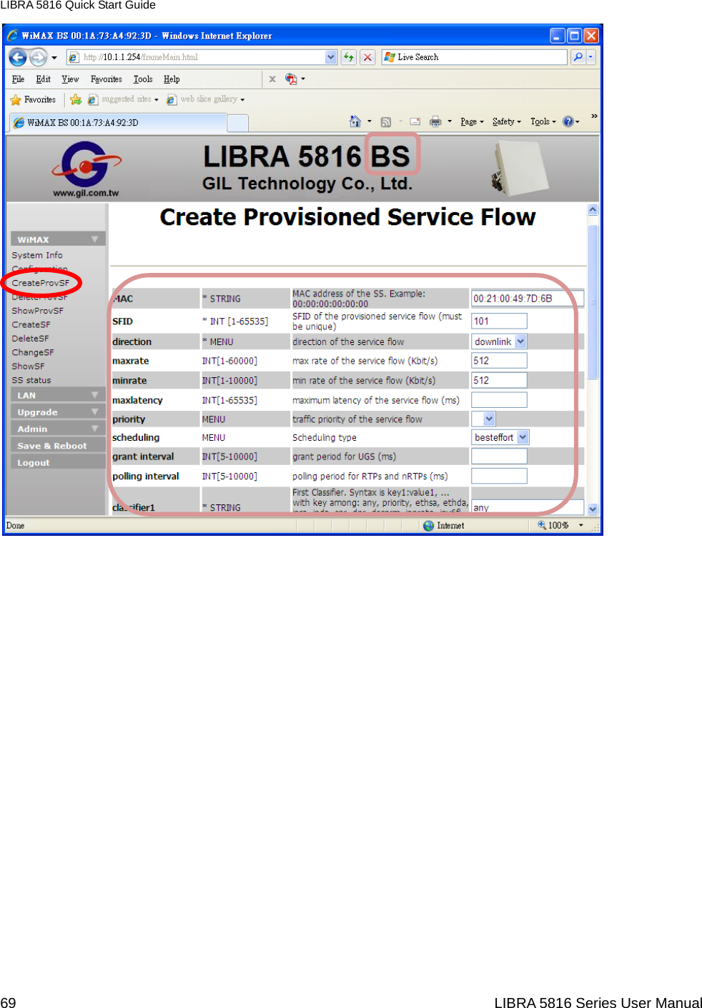
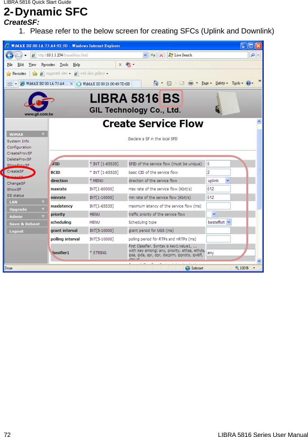
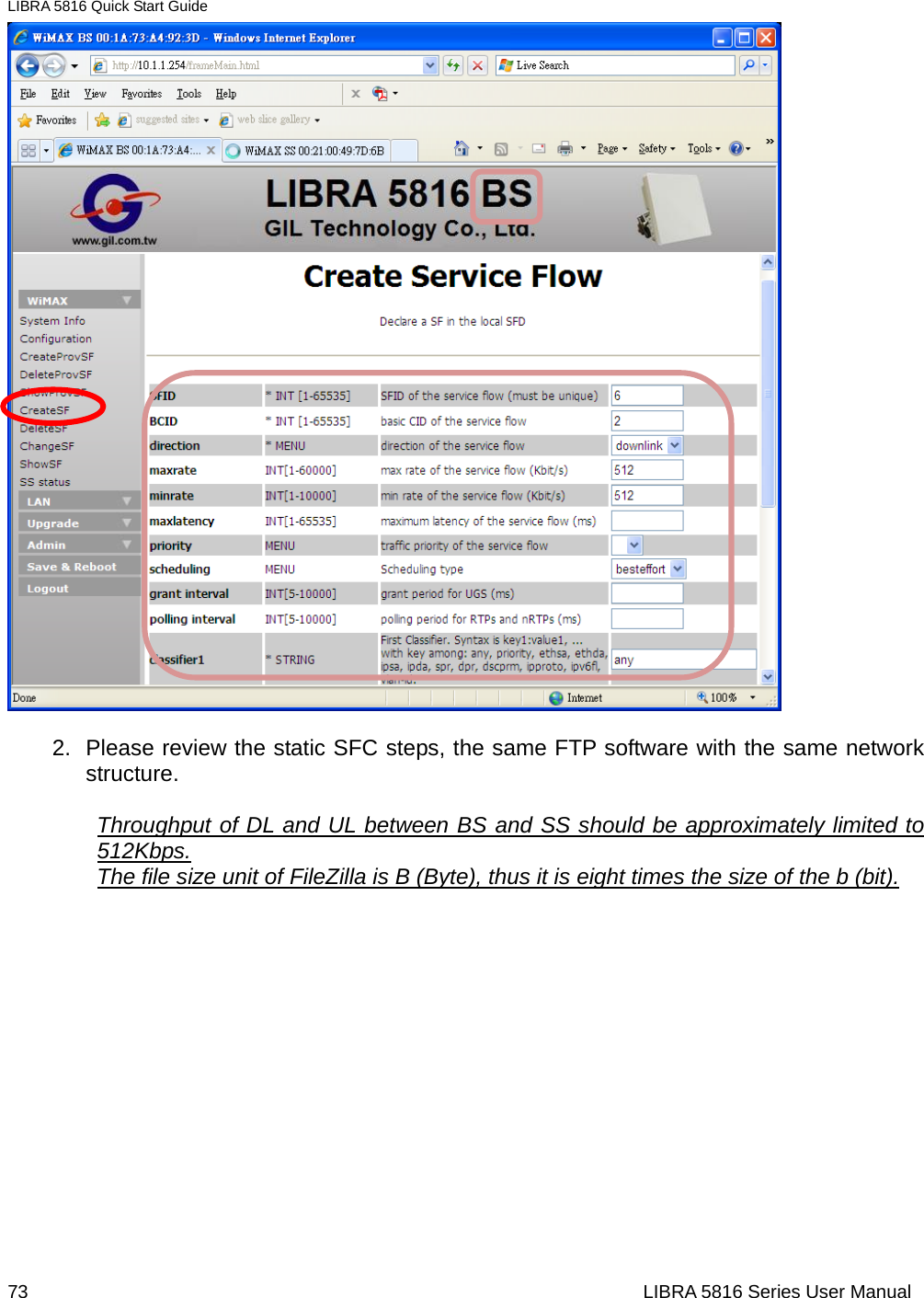
![LIBRA 5816 Quick Start Guide 56 LIBRA 5816 Series User Manual Before SFC Configuration All items of those related command have their own definition as below: MAC Media Access Control address of the SS BCID Basic Communication Identifier SFID SF Identifier direction DL or UL of the SF maxrate Maximum data rate of the SF minrate Minimum data rate of the SF maxlatency Maximum latency of the SF priority Traffic priority of the SF scheduling QoS type selection grant interval The grant period between SS and BS (UGS mode only) polling interval The polling period between SS and BS(rtPS and nrtPS) -classifier1~4 (Syntax definition and format instance) any Defines this classifier that matched all packets. Format: any priority Priority of this classifier, integer range is [0..255]. The highest priority is 255, default values is 128. Format: priority:55 ethsa Ethernet source address. Format: ethsa:00:11:22:33:44:55 ethda Ethernet destination address. Format: ethda:00:1A:2B:3C:4D:5E ipsa IP source address. Format: ipsa:192.168.10.68 ipda IP destination address. Format: ipda:192.168.10.33 spr Source port range. Format: spr:1230 – 1240 dpr destination port range. Format: dpr:1510 – 1520 dscprm Different Service Code Point range and mask. Format: dscprm:13:57:63](https://usermanual.wiki/GIL-Technology/GILBS/User-Guide-1096933-Page-56.png)