GRAUPNER 16005800 Gyro Receiver Graupner/SJ HoTT User Manual 33583 de en fr indd
GRAUPNER CO., LTD. Gyro Receiver Graupner/SJ HoTT 33583 de en fr indd
UserManual.wiki
>
GRAUPNER
>
16005800 User Manual
User Manual
Navigation menu
Upload a User Manual
Namespaces
Wiki Guide
HTML
PDF
Info
Views
User Manual
Discussion / Help
Navigation

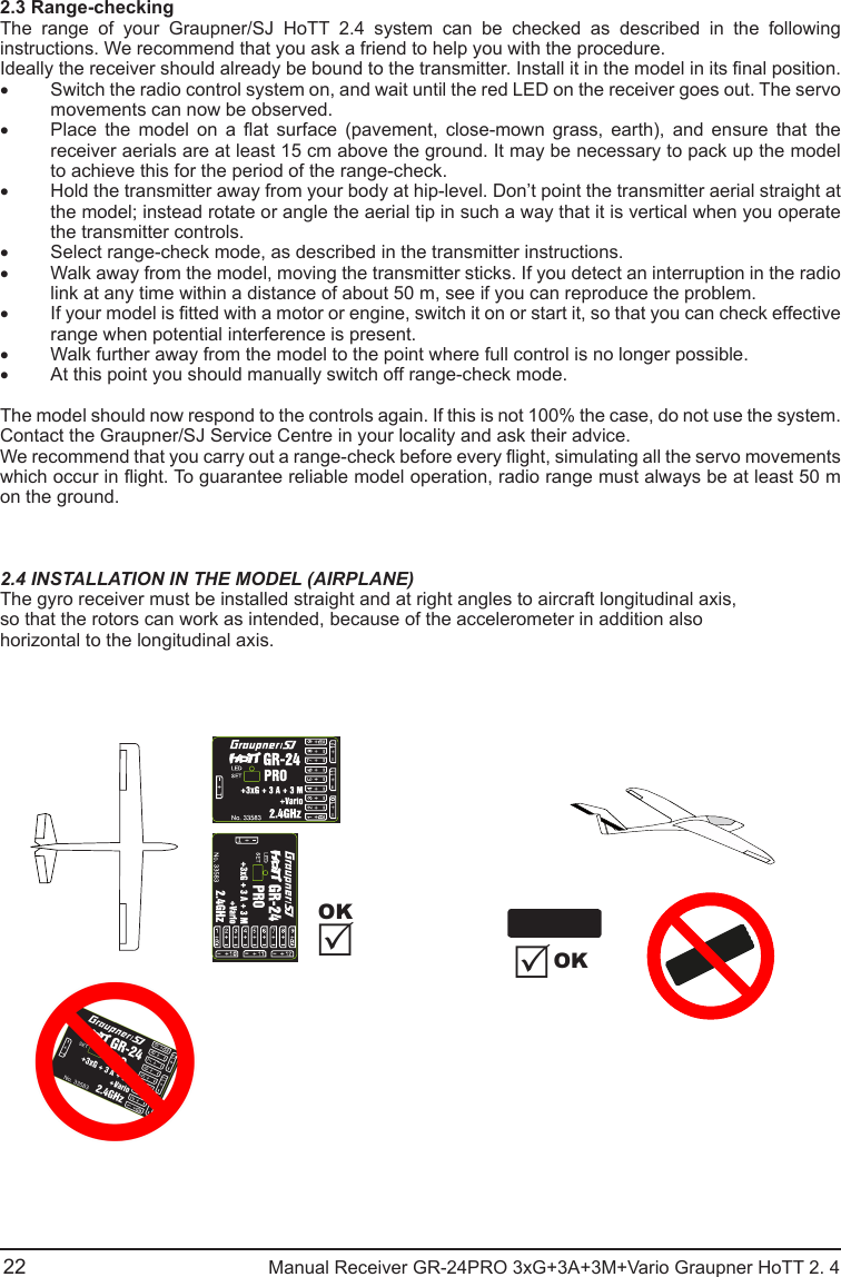
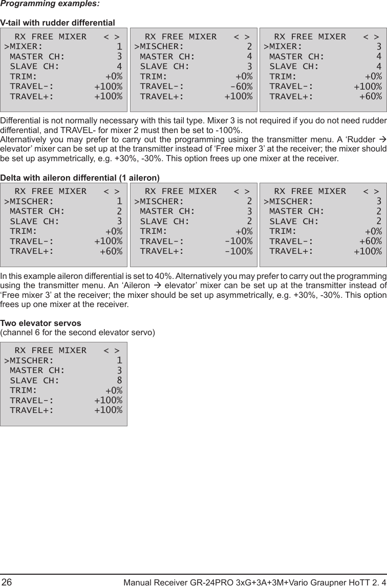
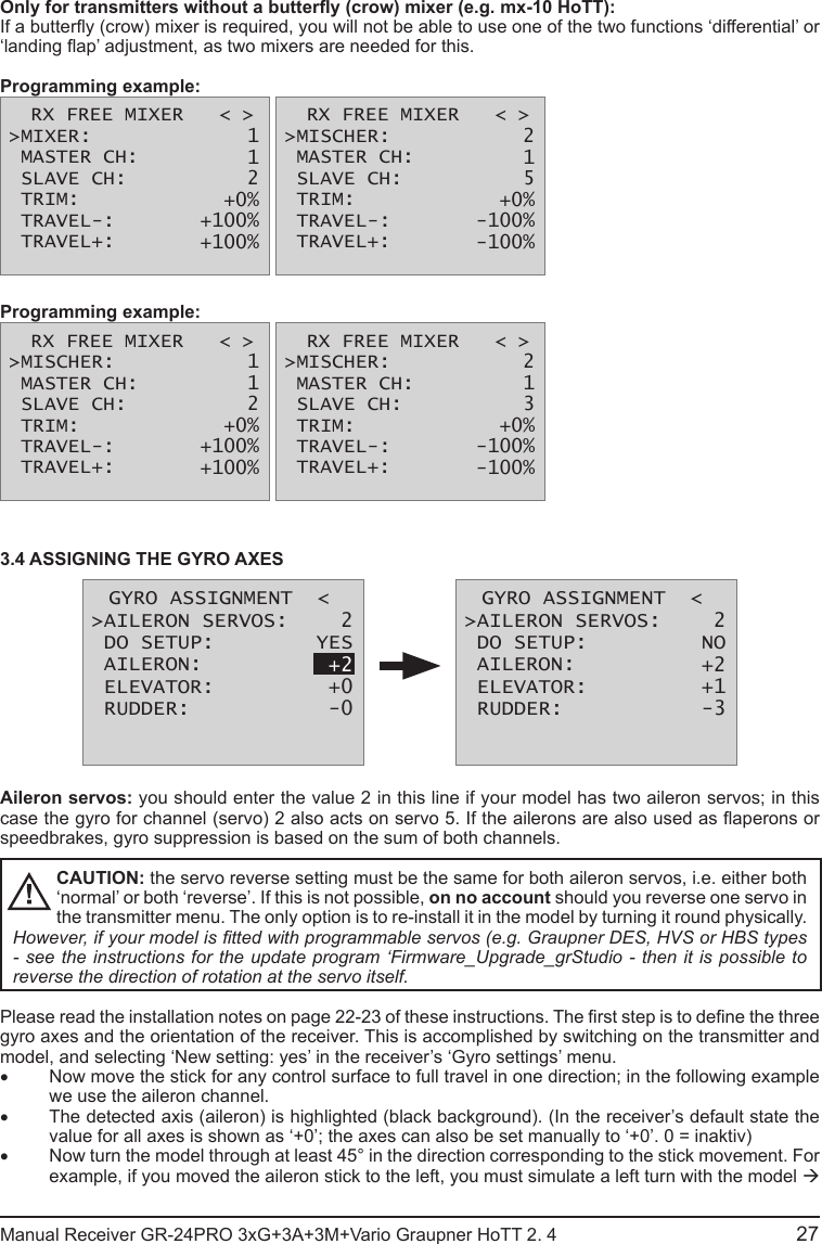
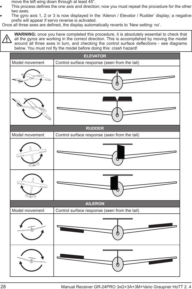
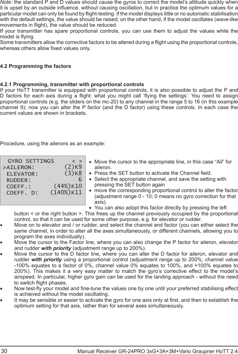
![GR-24PRO 3xG+3A+3M+Vario Graupner HoTT 2. 4 52Manufacturer’s declarationContent of the manufacturer’s declarationIf material defects or manufacturing faults should arise in a product distributed by us in the Federal Republic of Germany and purchased by a consumer (§ 13 BGB), we, Graupner/SJ GmbH, D-73230 Kirchheim/Teck, Germany, acknowledge the obligation to correct those defects within the limitations described below.The consumer is not entitled to exploit this manufacturer’s declaration if the failure in the usability of the product is due to natural wear, use under competition conditions, incompetent or improper use (including incorrect installation) or external inuences.This manufacturer’s declaration does not affect the consumer’s legal or contractual rights regarding defects arising from the purchase contract between the consumer and the vendor (dealer).Extent of the guaranteeIf a claim is made under guarantee, we undertake at our discretion to repair or replace the defective goods. We will not consider supplementary claims, especially for reimbursement of costs relating to the defect (e.g. installation / removal costs) and compensation for consequent damages unless they are allowed by statute. This does not affect claims based on legal regulations, especially according to product liability law.Guarantee requirementsThe purchaser is required to make the guarantee claim in writing, and must enclose original proof of purchase (e.g. invoice, receipt, delivery note) and this guarantee card. The purchaser must send the defective goods to us at his own cost, using the address stated below.Graupner/SJ GmbH, Service Department,Henriettenstr.96, D 73230 Kirchheim/Teck, GermanyService Department: tel. [0049] 7021-722130The purchaser should state the material defect or manufacturing fault, or the symptoms of the fault, in as accurate a manner as possible, so that we can check if our guarantee obligation is applicable.The goods are transported from the consumer to us and from us to the consumer at the risk of the consumer.Duration of validityThis declaration only applies to claims made to us during the claim period as stated in this declaration. The claim period is 24 months from the date of purchase of the product by the consumer from a dealer in the Federal Republic of Germany (purchase date). If a defect arises after the end of the claim period, or if the evidence or documents required according to this declaration in order to make the claim valid are not presented until after this period, then the consumer forfeits any rights or claims from this declaration.Limitation by lapse of timeIf we do not acknowledge the validity of a claim based on this declaration within the claim period, all claims based on this declaration are barred by the statute of limitations after six months from the time of implementation; however, this cannot occur before the end of the claim period.Applicable lawThis declaration, and the claims, rights and obligations arising from it, are based exclusively on the pertinent German Law, excluding the norms of international private law, and excluding UN retail law.](https://usermanual.wiki/GRAUPNER/16005800/User-Guide-2133084-Page-20.png)