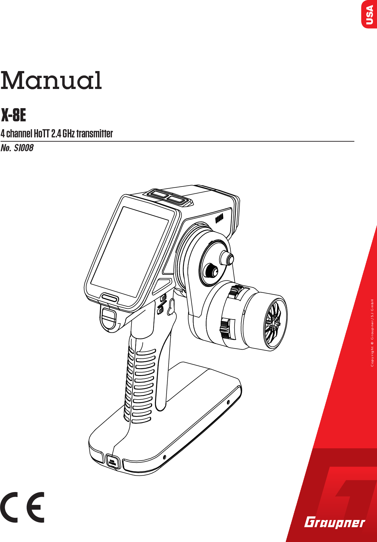
GRAUPNER 16006500 2.4GHz Radio Controller User Manual Users manual

GRAUPNER CO., LTD. 2.4GHz Radio Controller Users manual

Users manual

USANo. S10084 channel HoTT 2.4 GHz transmitterX-8EManualCopyright © Graupner/SJ GmbH
2 / 48 S1008_X-8E_jh_V1
3 / 48S1008_X-8E_jh_V1IndexIntroduction ..........................................................................5Service Center .....................................................................5Intended Use ........................................................................6Package Content .................................................................6Technical Data .....................................................................7Declaration of Conformity ..................................................7Symbols Explication ............................................................8Safety Notes ......................................................................... 8For your safety by handling the battery ................................9Control Elements and Connections .................................11Buttons and Switches Layout ..........................................11Commissioning ..................................................................12Battery connection ............................................................12Battery charging ................................................................ 12Transmitter power switch ..................................................12Tension Spring Adjustment ..............................................13Adjusting Steering Wheel Position ..................................13Converting the Steering Wheel for Left-Handers ...........14Installing the Steering Wheel Adapter .............................15RF SET ................................................................................16Binding .............................................................................16Channel features (CH FUNCTION) .....................................17Range test ........................................................................18Start Display ....................................................................... 19Main Menu ..........................................................................21H/W SET .............................................................................21TELE. (Telemetry Menu) ....................................................22Setting & Data View ..........................................................22RF Status View..................................................................22Voice Trigger .....................................................................23Device Management .........................................................23Secret Mode .......................................................................24Announcements (Voice Update) ........................................24Language change .............................................................24Steering wheel and throttle lever calibration .......................25Interface (BT SPEED) ........................................................25
4 / 48 S1008_X-8E_jh_V1Display Warnings ...............................................................26Voltage Display Calibration ..............................................26Change the Values in an Input Field ................................27M-SEL (Model Selection) ..................................................27REVERSE (Servo Reverse) ................................................27TRIM ...................................................................................27TRA ADJ (E.P.A.) ................................................................28DR/EXP (Dual Rate/Exponential) .....................................28B.R.A. ..................................................................................29B-MIX ..................................................................................30TH RESP (Throttle Response) ..........................................30IDLEUP (Pumping) .............................................................30PROFILE .............................................................................31S/SPEED .............................................................................32START .................................................................................32TIMER .................................................................................33SW SET ...............................................................................34FAIL SAFE ........................................................................... 36SERVO (S View) .................................................................. 36P/MIX ..................................................................................37AUX .....................................................................................38S/MODE ..............................................................................38A.B.S ...................................................................................40Operating Receiver GR-8 .................................................. 41GR-8 Receiver Telemetry Menu .......................................42Firmware Update - Transmitter ........................................43Firmware Update - Receiver ............................................44Battery Disposal ................................................................45Care and Maintenance ......................................................45Warranty .............................................................................45
5 / 48S1008_X-8E_jh_V1IntroductionThank you for purchasing the Graupner X-8E HoTT radio. This radio will transform the way you have been experiencing surface radios and add a new level of user experience between you and your model. The X-8E is easy to use and setup using the TFT color and touch screen.  The voice notifications will even further enhance your user experience.You can get more out of your X-8E using our wide selection of telemetry speed controllers and telemetry ESC’s. All HoTT com-patible products can be setup and programmed directly wire-less from the X-8E. No need for computers or programming boxes!Check us out regularly on the web for new changes and revi-sions of our manuals and firmware at www.graupnerusa.com.This product complies with national and European legal require-ments.To maintain product condition and to ensure safe operation, you must read and follow this user manual and the safety notes before use! Note This operating manual is part of the product.  It contains important information concerning operation and handling.  Keep these instruc-tions for future reference.  Please pass this on to future owners or third parties. Service CenterGraupner USA – OPENHOBBY LLC3941 Park Dr., Suite 20-571 El Dorado Hills, CA 95762 United StatesPhone: (855) 572-4746 x2Hours: Mon – Fri 9:00am – 4:00pm PSTEmail: service@graupnerusa.com Online Support: www.graupnerusa.comGraupner Online    For service centers, downloads, upgrades and product list, visit our web site at www.graupnerusa.com.
6 / 48 S1008_X-8E_jh_V1Intended useThe  X-8E HoTT transmitter is an ergonomically and technically modern 8 function radio control system in 2.4GHzHoTT tech-nology for ambitious and professional RC car and speedboat drivers. The X-8E HoTT transmitter is designed exclusively to be used in battery-powered, unmanned radio controlled models; any other use is not allowed. For any improper use no warranty or liability is accepted.Read through this entire manual before you attempt to use the X-8E HoTT transmitter.Graupner/SJ constantly works on the development of all prod-ucts; we reserve the right to change the item, its technology and equipment.The product is not a toy. It is not suitable for children under 14 years. The operation of the X-8E HoTT transmitter must be per-formed by experienced modelers. If you do not have sufficient knowledge about dealing with radio-controlled models, please contact an experienced model builder or a model club.Package content X-8E transmitter GR-8 Receiver LiPo battery 1S 5000 mAh USB update cable set (No.S8500, 7168.S) Micro SD card Steering wheel adapter 10 degree and cover Manual
7 / 48S1008_X-8E_jh_V1Technical DataX-8E transmitter dataOperating voltage 3.4 to 6 VFrequency 2.4 GhzWeight 1.44 lb  (657 g)Modulation FHSSRange 1640 ft  (500 m)Control functions 4Power consumption max. 600 mATemperature range 14° to 130°F  (-10 to +55 °C)Antenna type Patch antennaDimensions 8.6 x 7.3 x 5.5 in GR-8 receiver dataOperating voltage 3.6 to 8.4 VFrequency 2.4 GhzWeight  0.24 oz  (6.9 g)Modulation FHSSRange 1640 ft  (500 m)Control functions 4Power consumption 80 mATemperature range 14° to 130°F  (-10 to +55 °C)Aerial length 4.3 in  (110 mm)Dimensions 1.18 x 0.82 x 0.56  inDeclaration of conformityS1008 / X-8EGraupner/SJ declares that the product is conform to EU norms.EN 301 489-1 V1.9.2EN 301 489-17 V2.2.1EN 300 328 V1.8.1EN 60950-1:2006 + A11:2009 + A1:2010 + A2:2013EN 62311:2008
8 / 48  Symbols explication!  Always observe the information indicated by this warning sign. Particularly those which are additionally marked with the signal words CAUTION or WARNING.      WARNING indicates the potential for serious injury.     CAUTION indicates possibility of lighter injuries. Note indicates potential malfunctions.Attention indicates potential damages to objects.Safety notesGeneral!  These safety instructions are intended to protect this product, yourself and the safety of others.  Please read this section very carefully before using this product!To avoid risk of suffocation, keep packaging materials away from babies and small children. Supervision by an experienced adult is required for chil-dren, persons mentally or physically handicapped, nov-ices, or anyone not capable of safely using this product. Always perform a range and function test on the ground before you use your model (hold your model tight). Repeat the test with running motor and with short throttle bursts. Check all relevant laws and regulations before using this remote control model. These laws and regulations must be observed in for the safety of yourself and others and may vary by state, region, or country. Special liability insurance policies are mandatory for all device operations. If you already own a device, determine if the respective model is covered by your insurance.
9 / 48S1008_X-8E_jh_V1 Protect all equipment from dust, dirt, moisture, vibration and excessive heat or cold. The models may only be operated remotely in normal outside temperatures ranging from 14° to 130°F (-10°C to 55°C). Maintain frequent updates of your HoTT components with the latest firmware version. For additional questions or support, contact the Graupner USA Service Center, or an experienced user.Battery Safety  CAUTION Protect batteries from dust, moisture, heat and vibrations. For use in dry locations only. Do not use damaged batteries. Batteries not handled properly may catch fire, explode, or cause irritation and burns. To extinguish a battery fire use either water, CO² or sand. Batteries should not be heated, burned, short-circuited, incorrectly inserted, modified, soldered or welded. Charge batteries in a room outfitted with a smoke detec-tor,  on a non-flammable, heat-resistant and non-conduc-tive surface. Keep away from combustible or highly flam-mable objects while charging. Always monitor batteries during the charging process. Do not exceed the maximum quick-charging current specified for the respective cell type. If a battery reaches temperatures above 140°F (60°C) while it is being charged, immediately stop charging and let the battery cool down to approximately 86 - 104°F  (30 - 40°C). Never charge batteries that have already been charged, are hot or are not fully discharged. If a cell in a battery pack heats up following a quick-charge process, this may indi-cate a defective cell. Discard the battery immediately!!
10 / 48 S1008_X-8E_jh_V1 Damaged or corroded batteries may leak an electrolyte that is caustic and should not be touched or come into contact with your skin or eyes. In case of emergency, rinse thoroughly with water and seek immediate medical attention. Always fully recharge the battery.Special instructions on charging LiPo batteries To charge and discharge LiPo batteries, only use specifi-cally designed chargers/dischargers with balancer con-nector. The white connector (cell count + 1 pole) is designed for the connection to a LiPo balancer or a battery charger as a single cell charger with a manual cell balancer. Always charge the battery with the balancer connector.Safety notes for stocking LiPo batteries LiPo batteries should be stored with a voltage of about 3.8V per cell. If the cell voltage falls below 3V, then the bat-tery must be charged. Fully discharging or storing a bat-tery with a cell voltage < 3V renders the battery useless. Exersize safety procautions when charging and transport-ing your LiPo batteries.  Always use a safety bag.
11 / 48S1008_X-8E_jh_V1Control Elements and connectionsButtons and Switches Layout1.  Touch Display2.  Steering wheel3.  Throttle lever4.  Earphone socket5.  SD card slot6.  Data socket7.  Mini USB socket8.  On/off switches9.  Direct button S1 (see chapter SW  SET)10. Direct button S2 (see chapter SW  SET)1. PS 12. PS 23. PS 34. DV5. TR 16. TR 27. TR 38. TR 49. TR 51132456788991245 6 783910
12 / 48 S1008_X-8E_jh_V1CommissioningBattery connectionRemove the cover from the bottom of the transmitter and con-nect the battery, paying attention to the correct polarity. Shut the cover and ensure it is securely closed.Set the the battery warning threshold in accordance with the battery used. (see Chapter “SYS SET”)If a voltage warning is triggered, charge the batteries.Battery chargingCharge the LiPo batteries in the transmitter through the micro USB socket using the USB cable provided. For all other battery types, use an USB connection, e.g. a PC USB port or an USB net adapter. During the charging process the LED under the dis-play lights up red. When the battery is full the LED turns off.Alternatively, you can charge the battery outside the transmitter with an RC battery charger (not included).Transmitter power switchOn the top of the transmitter there are two buttons. To turn on the transmitter with RF off, push the right button for about 2 sec-onds. When the RF mode is off, a safety feature is activated that prevents switched-on models from accidentally starting during programming.  Additionally, power consumption is reduced, significantly conserving battery life.To turn on the transmitter with RF on, push the left button.Battery socketOn - OffSwitch
13 / 48S1008_X-8E_jh_V1Tension spring adjustmentAdjusting the steering wheel positionTo adjust the steering wheel tension spring, locate the adjusting screw in the housing below the wheel.Using a hex key, turn the screw left or right to increase or decrease tension force.To adjust the throttle lever tension spring, locate the adjusting screw in the housing at the throttle lever.Using a hex key, turn the screw left or right to increase or decrease tension force.To adjust the steering wheel position forward or backward, remove the X-8E logo cover, located above the steering wheel. Loosen the two screws and maneuver the steering wheel into desired position. Retighten the two screws to secure.
14 / 48 S1008_X-8E_jh_V11.2.3.Converting the steering wheel for left-handersThe entire steering wheel can be converted to the left side for operation by left-handers.1.  Remove the X-8E logo cover (see following figure).2.  Unscrew the steering wheel (2 screws).3.  Unplug the steering wheel cable.4.  Mount the steering wheel on the left side and re-plug the cable.5.  Tighten the steering wheel and replace the X-8E logo cover.4.Attention  After the conversion, check all steering wheel func-tions, buttons and rotary controls before operating the model again!5.
15 / 48S1008_X-8E_jh_V1Installing the steering wheel adapterThe steering wheel position can be adjusted 10 degrees through an adapter.1.  Remove the steering wheel.2.  Remove the four long screws under the wheel.3.  Remove the steering wheel mechanism and disconnect the connector.4.  Adjust the adapter to preferred position and secure with the four short screws.5.  Reconnect the connector6.  Install the steering wheel mechanism on the adapter part and reattatch the steering wheel.Attention  After the conversion, check all steering wheel func-tions, buttons and rotary controls before operating the model again!
16 / 48 S1008_X-8E_jh_V1RF SETBinding and range testBindingTo establish a communication link, bind the Graupner-HoTT receiver to the X-8E Graupner-HoTT transmitter. The binding process has already been performed for the transmitter and the receiver included. However, binding is required for each addi-tional receiver added to this transmitter.  To bind additional receivers:NOTE: The transmitter can be turned ON or OFF with one of two buttons.  When using the white button, the transmitter RF functions are completely disabled and it will not be possible to turn on the RF or bind a receiver.1.  Turn on the transmitter using the RED button.  If no receiver is bound to the model, select SET.  Selecting SET will bring up the bind finction of the RF SET menu.2.  Select the correct RF system.  (HoTT V2 for the GR-8 or HoTT for the GR-4.)  GR-8: The red LED flashes slowly when there is no communications link.  GR-4: The red LED glows solid red when there is no communications link.3.  Press and hold the SET button on the receiver for about 3 seconds.4.  Press the BIND button on the transmitter. 5.  The OFF will change to CHK momentarily.6.  If the bind is successful, the number of receiver channels will be displayed.  If not successful, the button will return to OFF status.Repeat the bind process until successful.  It is all a matter of tim-ing.  (Counting "one thousand one, one thousand two, one thousand three" will help with the timing.)Receiver Transmitter displayBinding buttonBACK NORMALHOTT V2RF  SYSTEMBINDTELEMETRYOFFON
17 / 48S1008_X-8E_jh_V1Meaning of the individual menu itemsRF SYSTEM = HoTT for receiver (GR-4/12/16/18/24/32)           HoTT V2 for receiver with SUMD-V2 (GR-8)BIND = Displays bound receiver channelsRF ON/OFF = Displays if RF is switched on or offRANGE TEST = Range test (see chapter “Range test”)CH FUNCTION ==> (only available in HoTT V2 operation with compatible receiver)Channel features (CH FUNCTION)Only available in HoTT V2 operation with compatible receiver!Each channel is capable of the following signals: USR1m50 : ULTRA SIGNAL 1.5msec FSR3m00 : FAST SIGNAL 3.0msec SUMD-V2 : FAST SIGNAL BUS 3.0msec NSR6m00 : NORMAL SIGNAL 6.0msec NSR12m0 : NORMAL SIGNAL 12.0msec NSR24m0 : NORMAL SIGNAL 24.0msecUse this menu to adjust the servo properties by setting the indi-vidual channel properties. (For more information refer to the servo’s user’s manual.) AttentionThe SUMD-V2 setting can only be used for Graupner servos, sensors and controllers that support this function!Notice: To save receiver settings, follow the instructions on the screen in the following order:1. Switch receiver off2. Switch transmitter off3. Switch transmitter on4. Switch receiver onTo verify the receiver settings are displayed, check the telemetry menu.  BACKNSR12m0CH 3NORMAL SERVOCH 4CH 2CH 1CH FUNCTNSR12m0NSR12m0NSR12m0BACK NORMAL SERVOCH FUNCTReboot as follows:1. Power receiver off2. Switch transmitter off3. Switch transmitter on4. Power receiver onOKBACK NORMALHOTT V2RF  SYSTEMBINDRF ON/OFFR04ONRANGE  TEST OFF99secCH FUNCTION >>
18 / 48 S1008_X-8E_jh_V1Range testAlways perform a range test before each operation.  Have an assistant to help with the range test.  Range test instructions are as follows: 1.  Bind the receiver with the transmitter and insert into the model. Switch on the transmitter first, then the receiver. Servo movements can now be monitored. 2.  Place the model on a flat surface (cement, mowed lawn or level ground) with the receiver antennas at least 6 in (15 cm) above the ground. If necessary, place a support underneath the model during the test. Hold the transmit-ter at waist-level at a comfortable distance from your body. Do not point the aerial directly at the model.  Turn or angle the aerial tip so it stands vertical during oper-ation. In the “RF SET” menu, press OFF in the “RANGE TEST” line.  This switches the option ON and begins the range test.  The test will ramian active for 99 seconds, after which it will automatically switch off.  (Quit the range test at any time by pressing ON in the “RANGE TEST” line to switch this option OFF.) 3.  Walk away from the model and turn the wheel to simulate all servo movements and normal operations. If at any time you detect an interruption in the link within a range of about 164 ft (50 m), attempt to reastablish the link.4.  To check interference resistance, switch on an existing motor. Move away from the model until it no longer  responds. Manually terminate the range test mode. 5.  The model should now respond again. If not, do not use the system and contact the Graupner Service Center.6.  Ground range for safe operation and handling should be within 164 ft (50 m).BACK NORMALHOTT V2RF  SYSTEMBINDRF ON/OFFR04ONRANGE TEST ON87secCH FUNCTION >>
19 / 48S1008_X-8E_jh_V1Start displaySymbol explinationTX3.9V4.8VRXRX000:00.0ST THST TRIM  TH TRIM0%100%0%0%CH3 CH4BK D/R ST D/RPS1+100% 100%PS2OFF OFFM - 1 MODEL  1NORMALO.TIME      0  :   23  :  02 B.TIME    0    :   11  :  59CH3 CH41Voice output (announce)Blue = Active / Gray = InactiveEarphones (announce)Blue = Connected / Gray = DisconnectedDisplay rotation (function - press)Normal = 1 / 90° right = 2 / 90° left = 3SD card (indicator)Blue = Inserted / Gray = Not InsertedDisplay warnings (function - press)Warnings display (see chapter “Warnings”)Transmitter battery display (function - press)Graphic representation of battery power level and green voltage information  (see chapter “Voltage indicator calibration”).  Blinks while battery charging.Reception strength (display)Red bars representing receiver (RX) field strength.RF switched on (display)Blue = RF On / Gray = RF OffTransmission strength (display)Green bars representing transmitter (TX) field strengthReceiver (RX) input voltage.RXTXRX     4.8V3.9 V
20 / 48 S1008_X-8E_jh_V1BackdfgsdM-1Tap for model memory selectionModel 1Tap to input the model nameProfileTap to switching between the five profiles.Main menuTap to move to main menuTelemetry menuTap to move to telemetry menuBar display (display only)SteeringThrottlePercent display / status displayShows the position percentage of steering, throttle, dual-rate and the switch state of PS1 and PS2.Tap this display screen to access a detail screen for more infor-mation.  (Display only.)Model use time (see chapter “Timer”).Battery use time (see chapter “Timer”).Laps timer: Tapping opens the “Timer” menu.M - 1MODEL  1NORMALTRIM ST BACK NORMAL0%TRIM TH 0%PS1 OFFCH3 0% -100%D/R ST LPS2 OFFPS3 OFFBK D/R +100%CH4 0%000:00.0TH STBACK
21 / 48S1008_X-8E_jh_V1Main MenuPush the “F” icon in the main display to access the menu.  The menu system is comprised of 3 pages.  Scroll between the pages by tapping the <+ and -> directional buttons at the bot-tom of the screen. Tap the blue icons to access the related sub-menu screen.H/W SETThe H/W SET menu controls system setup and display settings. To switch between System and Display tap the button to the right of H/W TYPE.System settings (H/W TYPE = SYSTEM)Battery type - This transmitter only works with a LiPo battery.LiPo - The warning threshold is automatically set to 3.6V.Battery warning - The battery warning threshold can be manually adjusted by 0.1V incriments.Startup tone - Turn ON or OFF the startup melody. Voice volume - Speaker volume control for voice announce-ments.  OFF = no sound / 05 = highest volume.  Power saving - Turns ON  or  OFF a power-saving mode that begins a 1 minute countdown following a period of inactivity.  After the countdown the transmitter will automatically switch off.  Secret Mode - Refer to the Secret Mode chapter for additional information on these settings.3.9VMODEL  1BACKSW SET S/MODE SERVOAUX TELE.3.9VMODEL  1BACKM-SEL RF SET REVERSETRA ADJ DR/EXP TRIMB.R.A. IDLE UP TIMER3.9VMODEL  1BACKPROFILE REVERSEP/MIXS/SPEED STARTA.B.SB-MIXTH RESPH/W SETBACK NORMAL SERVOBatt type LI-PO3.4 VBatt WarningStartup toneVoice volumePower savingON03OFFH/W Type SYSTEMSecret Mode SET
22 / 48 S1008_X-8E_jh_V1Display settings (H/W TYPE = DISPLAY)Brightness - Adjust brightness level from 1 - 20Display light - Switching the backlight ON or OFF.Touch sense - Adjust the touch screen sensitivity.1 = very sensitive / 5 = reduced sensitivity.LED control - Opens a separate page in where users can switch on/off the transmitter's LED lights or change their colors.  Display mode - Change the display orientation.        1 = Normal.  2 =  90° right rotation.  3 = 90° left rotation.RFID - Displays transmitter's identification number.TELE. (Telemetry Menu)Setting & Data ViewThis menu option allows setup of receiver's telemetry menu.Refer to the receiver's user's manual for specific telemetry setup information.  RF Status ViewThis display displays the frequency band and channel assign-ments.BACK NORMAL SERVOBrightness 15OFFBack lightTouch senseLED controlDisplay mode1SET1H/W TYPE DisplayRFID                                 55555BACK NORMAL SERVOLEFTOFFRIGHTFRONTBLUEREDBACK NORMAL SERVOSETTING & DATA VIEW >>RF STATUS VIEWVOICE TRIGGERDEVICE MANAGEMENT>>>>>>BACK NORMAL SERVOQUATDERRVc96% 100%STR- 56 dB1 2 3 4 5 6 7 8 9 10 11 12 13 14 151 2 3 4 5 6 7 8 9 10 11 12 13 14 15RD - 36 dB9ms4.9 4.9Vm
23 / 48S1008_X-8E_jh_V1Voice TriggerOnly connected sensors and receivers are active.REPEAT: If the REPEAT function is activated (via SW/FUN menu, VOICE RPT button), set the repetition frequency of the voice output here.TRIGGER:  Switch ON or OFF voice output from play list.FIXED VOICE: Tap to open a drop-down menu of all voice announcemnts available on the SUMD-V2 system.  Device ManagementIf the SUMD-V2 system's channels are set in the RF SET menu at "CH FUNCTION", this menu manages the administration of all devices connected to the receiver. (display only)Device ListThis menu shows a list of all connected devices and to which receiver port they are connected.  Devices can be assigned to channels here.New DevicePlug in a new device and push FIND.  A pop-up menu will appear showing the device is being located and assigned to a device list number.  Once found, tap OK.    Repeat this process for each new device to be assigned to the list.BACK NORMAL SERVOREPEAT 10s--OFFOFFTRIGGERFIXED VOICETRANSMITTERPLAY LISTCAR ESCGENERALVARIORECEIVERSERVOAIR ESCELECTRICGPSBACK NORMAL SERVODevice ListLISTNew DeviceLive Log DeviceFIND>>BACK NORMAL SERVONo00 -0102030405Device CH PORTRECEIVER -BACK NORMAL SERVODevice ListLISTNew DeviceLive Log DeviceFIND>>FINDINGNO. 00OK
24 / 48 S1008_X-8E_jh_V1Live Log DeviceIf the device is equipped with the Bluetooth module S8351, real-time telemetry data can be logged and analyzed and transmit-ted via features available found in the Firmware Upgrade Studio.  This menu logs, lists and numbers all devices being tracked through this option. Refer to the Secret Settings  chapter for additional information on setting up this option.  Secret ModeThe "Secret mode" option is the last item on the "H/W SET" menu.Announcements (Voice Update)By default, all voice announcements are recorded in German and are saved in a voice packet that is stored in the transmitter's internal memory. They can be replaced by a voice packet of a different language at any time.On the micro SD card (included) choose from the following lan-guage options: German, English, French, Dutch, Italian and Spanish.You can also download additional language packets at  www.graupner.de.Language changeLanguage change step by step:1.  Insert the included SD memory card in its slot.2.  Use the left switch to turn the transmitter on in RF mode.3.  Select the "Secret mode" menu in the H/W SET menu.4.  Tap the "Voice Update" button.5.  Highlight the language from the list by tapping the appropri-ate button.6.  Tap the "Load" button. The selected language packet will be stored in the transmitter memory.7.  The loading process is finished as soon as the progress bar at the lower edge of the display disappears.8.  When this process is finished, switch the transmitter OFF.BACK NORMAL SERVO0102030405Device NumberBACK Secret Mode>>Voice UpdateStick Calibration >>Interface USB PORTBT Speed NORMALBACK Voice File ListVoice2_German01Voice2_English02Voice2_France03Voice2_Italiano04Voice2_Spain05Voice2_Dutch06Load
25 / 48S1008_X-8E_jh_V1Steering wheel and throttle lever calibrationIf the center position of steering wheel or if the throttle lever does not neutralize to 0%control travel, you can check and correct it as follows.Stick calibration step by step:1.  Go to the "M-SEL" menu and tap on an open model memory slot to select.2.  Move to the "SERVO" menu without changing any trim settings or other program settings.3.  Center the steering wheel or the throttle lever by moving the steering wheel and the throttle lever to the middle position. If the throttle lever and the steering wheel are correctly centered, the display should match the one shown at left.4.  One at a time, move the steering wheel and throttle lever  as far as they will go in all directions without exerting force at their position limits.  The values should register between -100% and +100%.5.  If the throttle lever or the steering wheel does not reach the desired values, tap the "Stick Calibration" button in the "Secret Mode" option in the "H/W SET" menu.6.  Follow the prompts on the screen by moving the steering wheel and the throttle lever in the directions shown and keep them still. Confirm the position by tapping on the ENT button. Repeat this procedure for all of the indicated positions. If you have correctly calibrated all positions, a confirmation message will be displayed. Tap "OK" to save the calibrations. Tapthe "BACK" button to quit the pro-cess and return to the submenu "Stick Calibration".Interface (BT SPEED)Use this menu to assign transmitter ports for telemetry data transmission.  DATA PORTPlug in the external Bluetooth module S8351 to the DATA port on the rear side of the transmitter. In the BT SPEED line, FAST or NORMAL will automatically select depending on the trans-mission speed of the counterpart device.USB PORTPlug in the supplied connection cable 7168 to the micro USB port on the rear side of the transmitter to establish a connection with a PC.BACK NORMALSTL150%F150%R150%B150%0%0%TH0%0%0%CH3CH30%BACK0 %LEFTStick CalibrationENT
26 / 48 S1008_X-8E_jh_V1Display warningsTap the exclimation point symbol in the top line of the Start Display to open the warnings display screen-showing the current values for transmitter voltage (TX VOLT), receiver voltage (RX VOLT), signal strength (STRENGTH), speed controller current (ESC CUR.) and speed controller voltage (ESC VOLT).Acoustic (A-) and optical (S-) warnings can be activated or deactivated by tapping the ON or OFF buttons.Resets the alarms by tapping Clear (CLR). Voltage display calibrationFrom the Main Menu, tap on the battery symbol to pull up the voltage calibration display. Calibrate the voltage dis-play as follows:Voltage display calibration step by step:1.  Measure the battery voltage with a voltmeter.2.  Tap on the Cali. Data button.3.  Enter the data by changing the value by 2 or 10 unit incriments.4.  To SAVE tap and confirm the safety query through YES.5.  The new value is displayed under Tx VoltTX3.9V4.8VRXRX000:00.0ST THST TRIM  TH TRIM0%100%0%0%CH3 CH4BK D/R ST D/RPS1+100% 100%PS2OFF OFFM - 1 MODEL  1NORMALO.TIME      0  :   23  :  02 B.TIME    0    :   11  :  59CH3 CH4TX  VOLT          3.9 V        0 RX  VOLT          0.0 V        0 ESC  VOLT        0.0V        0 ESC  CUR.        0.0A         0 STRENGTH        0%        0 BACK CLR OFF ONA- S-BACK+234814+10-2-10SAVE3.95VTx Volt Cali.  DataNORMAL
27 / 48S1008_X-8E_jh_V1Change the values in an input fieldThe following three buttons are visable on the lower part of the display of many of the following menus. To raise or lower a value by pressing the <+  or -> buttons.   Reset the default value through the curved back-arrow button.M-SEL (Model Selection)Model settings can be managed and saved into memory slots by choosing from the following options: SEL - Change active model memories.IMP.M - Import model memories from the SD card.EXP.M - Export model memories to the SD card.RES - Reset a model memory to the factory presets.               Warning: All personal settings will be deleted!CPY - Copy the actual model memory in a new model mem-ory.REVERSE (Servo Reverse)The servo operates in two directions:Normal - ReverseTo change servo directions, tap the NORMAL/REVERSE but-ton of the related servo to toggle between options. If changing the throttle direction, a safety warning will appear.  Tap YES or NO to verify the selection and the change will take effect.TRIMThis trim function allows for the entire servo travel to be moved, i.e. full deflection position changes. In the second line is displayed the respective trim value that has been set through the buttons.Tap on the related button. Change the values by pushing the <+ or -> keys. Press the curved arrow key to reset to the default value (0%).BACKMODEL 101020304050607NEXTMODEL 2 SELMODEL 3 IMP.MMODEL 7MODEL 6 CPYMODEL 5 RESMODEL 4 EXP.M08 MODEL 809 MODEL 9BACKNORMALNORMAL SERVONORMALNORMAL NORMALST THCH3 CH4BACKNORMALNORMAL SERVONORMALNORMAL NORMALST THCH3 CH4WarningAre you sure?YES NOBACK0%SV/TRSTNORMAL SERVOTHTX/TR0%0% 0%CH 3 CH 40%SV/TRTX/TR0%0% 0%
28 / 48 S1008_X-8E_jh_V1TRA ADJ (End Point Adjustment)  End Point AdjustmentThis function sets the maximum travel of the servo per channel. The left and right deflection can be set separately in the range from 0%  -  150%. Press the related button. Change the values by pushing the <+ or -> keys. Press the curved arrow key to reset to the default value (100%).To set the DR (Dual Rate) and EXPO (Exponential) function for the steering and throttle channel, press the STEERING or THROTTLE button in the CH line. All setting changes are rep-resented in the diagram.Setting STEERING channelD/R: 0% - 100% Limit the steering course.  Press the <+ or -> keys to raise or lower value. Press the curved arrow key to reset to the default value (100%).EXP: -100% to + 100% Exponentially change the steering course.  Press the <+ or -> keys to raise or lower value. Press the curved arrow key to reset to the default value (0%). Setting THROTTLE channelD/R: 0% - 100% Limit the throttle course.  Press the <+ or -> keys to raise or lower value. Press the curved arrow key to reset to the default value (100%).EXP: -100% to + 100% Exponentially change the throttle course.  Press the <+ or -> keys to raise or lower value. Press the curved arrow key to reset to the default value (0%).FWD: Choose between forward and brake area.  Refer to the D/R and EXP settings described above and the FWD/BRK set-tings described on the following page.TYPE: Select between EXPO or throttle CURVECURVE: Refer to the setting instructions on the following page.BACK100%LEFTNORMAL SERVORIGHT100%ST100%BRK FW100%TH100%UP DN100%CH3100%UP DN100%CH4BACKSTEERINGNORMAL SERVOCH100%D/R0%EXPBACKTHROTTLENORMAL SERVOCH100%D/R0%EXPFWDTYPEEXPBACKDR/EXP (Dual Rate/Exponential)
29 / 48S1008_X-8E_jh_V1THROTTLE FWD point setting step by step:1.  Press the "ST OFF" button to switch to "ST ON".2.  Move the throttle lever. 3.  A green line moves horizontally through the diagram.4.  Press the +/- key to create a new point.  Multiple points can be set by pressing the arrow key.5.  Delete highlighted points by pressing the +/- key.THROTTLE FWD point moving step by step:1.  Press the "ST ON" button to switch to "ST OFF".2.  Press the <+ or -> keys to scroll through the points.  Points will highlight red when selected.  Delete highlighted points by pressing the +/- key.3.  Select the X-axis or the Y-axis button. Press the <+ or -> keys to change axis curve or to reposition points along the axis.TH.holdUse this option while programming a curve prevent the motor from running.  Tap the ON and OFF button to switch the throttle channel on and off. Brake force setting1.  Select the "THROTTLE" setting by pressing the "STEER-ING" button.2.  Select the "BRK" setting by tipping on the "FWD" button.3.  Moving the throttle lever.   The green axis line moves in the diaplay.4.  To adjust the force setting, select the percent button near "D/R" or "EXP".  Press the <+ or -> keys to raise or lower value.  Press the curved arrow key to reset the default value. B.R.A. (ATL)Break rate and travel setting menu.   RATE:  Factory default setting is F50:B:50.  Press the button in the RATE line to switch to F70:B:30 and move the servo center.B.R.A:  To adjust the travel, highlight the percent button in the B.R.A. line.  Press the <+ or -> keys to raise or lower value. Press the curved arrow key to reset to the default value (100%).BACKTHROTTLENORMAL SERVOX-axisCHONPOINT  ?       0%TYPECurveY-axisST  OFFFWDCurveTH.holdOFF+/-BACKTHROTTLENORMAL SERVOCHD/R +100%BRKEXP      0%BACK NORMAL SERVORATE     100%B.R.A    F50:B50BK FW0%
30 / 48 S1008_X-8E_jh_V1B-MIXBreak mixer options menu, including mixer channel assignment, mixer rate setting, delay time and ABS activation.ACT:   To activate the break secure function, press to change  INH (inhibit/off) to ON. RATE:   To set the break mixer part, press the percent button on the RATE line.  Press the <+ or -> keys to raise or lower value. Press the curved arrow key to reset to the default value (100%).  DELAY:   To set a delay time prior to activating the ABS, press the percent button on the DELAY line.  Press the <+ or -> keys to raise or lower value. Press the curved arrow key to reset to the default value (0.00s).  ABS:   To activate the ABS function, press to change  INH (inhibit/off) to ON.   TH RESP (Throttle Response)Throttle response settings menu.  The throttle and break travel can be adjusted in one percent incriments, causing the servo to automatically jump to the set value during operation.  This setting   can compensate backlash of the throttle linkage or throttle response weakness in lower ranges.FW: 0% - 100%  To set the throttle, press the percent button on the RATE line.  Press the <+ or -> keys to raise or lower value. Press the curved arrow key to reset to the default value (0%).  BK: 0% - 100%  To set the break, press the percent button on the RATE line.  Press the <+ or -> keys to raise or lower value. Press the curved arrow key to reset to the default value (0%).  IDLE UP (Pumping)Motor start function settings menu. Holds the throttle to a spe-cific value to enable a better start for cold combustion engines.                     POS:  To adjust throttle position, press the percent button on under POS.  Press the <+ or -> keys to raise or lower value. Press the curved arrow key to reset to the default value (0%).  NOTE: After starting the engine, this function must be deactivated; the throttle lever has no effect during the IDLE UP function.CTL:  Assign this function to a switch.  Refer to the SW SET chapter for additional information on how to program switches.BACKINHCH 3NORMAL SERVOCH 4ACTRATEDELAYABSINH+100% +100%0.00s 0.00sINH INHBACK NORMAL SERVOFW     0%BKBK FW0%     0%BACK NORMAL SERVOPOSNONEACTSETCTLPUMPINGON0%BK FW
31 / 48S1008_X-8E_jh_V1PUMPINGAutomatic throttle activation menu.  Set throttle strength and delay time to protect motor during refueling.POS: To set the strength of the throttle activation, select the per-cent button below POS.  Press the <+ or -> keys to raise or lower value. Press the curved arrow key to reset to the default value (0%).         DELAY: To set delay time between throttle activations, select the percent button below DELAY.  Press the <+ or -> keys to raise or lower value. Press the curved arrow key to reset to the default value (0.5s).      ACT:  Press ON or INH (inhibit/off) to switch the activation func-tion on or off.        CTL:  Assign this function to a switch.  Refer to the SW SET chapter for additional information on how to program switches.PROFILESet up to five different profiles for the model memories. Create names and assign settings to a programmable switch. (Refer to the  SW SET chapter for additional information on assigning switches.)Settings that have been changed in the other menus will be automatically populated in the assigned profile.Change profile name:1.  Select profile to be renamed by highlighting any line, 1 - 5.   2.  Press the NAM button at the bottom of the screen.3.  The current name appears in a field at the top of a new screen.  Use the red keypad to input a new name.4.  To save, press EN in the lower right side of the keyboard.5.  Press the BACK button to return to the main menu.  Copy profile:1.  Select the profile to copy by highlighting the profile name.2.  Press CPY.  A pop-up window will appear.3.  To select the target profile, tap to scroll through the saved profiles.   Press YES to confirm selection.Delete profile:1.  Select the profile to delete by highlighting the profile name.2.  Press DEL. Settings will reset to factory default values.  WARNING:  profile will be deleted without confirm query!BACK NORMAL SERVODELAYNONEACT0%CTLPOSINH0,5sBK THNONEBACKNORMALNORMAL SERVONEW NAM CPYDEL1PROFIL 1PROFIL 2PROFIL 3PROFIL 4ACTPROFILE2345CTLBACK Current Profile NamePHASE 1ANew Profile NameCAPS NUM SPECIALB C D E FG H I J K LM N O P Q RSTU V W XY Z CL SP DE ENFROM NORMALTARGETPROFIL 2YES NOCOPY
32 / 48 S1008_X-8E_jh_V1S/SPEEDSteering and throttle servo speed settings menu.For the steering servo, you can set the speed for left and right and for forward and return travel separately.For the throttle servo, a point can be set at which the speed is set in two steps.STEERINGHighlight the field to be adjusted by pressing the appriporiate button in the LEFT or RIGHT columns and TURN or RETURN lines.  Press the <+ or -> keys to raise or lower value. Press the curved arrow key to reset to the default value (100).  THROTTLEHIGH or NEUTRAL:  Select the field to be adjusted by pressing the appriporiate button.  Press the <+  or -> keys to raise or lower value. Press the curved arrow key to reset to the default value (100).POINT:  To set the switchover point between both ranges, high-light the button under POINT.  Press the <+ or -> keys to raise or lower value. Press the curved arrow key to reset to the default value (50).STARTAutomatic start function settings menu.RATE: To allow a quick start without spinning the drive wheels while the throttle is held on a specific value, press the percent button below RATE. Press the <+ or -> keys to raise or lower value. Press the curved arrow key to reset to the default value (0%).T/POS:  To use this function, first assign a switch that sets the START function to READY.  When the throttle lever exceeds the set trigger point, the READY (standby) mode is activated.  To adjust the trigger position, press the percent button below T/POS.  Press the <+ or -> keys to raise or lower value. Press the curved arrow key to reset to the default value (0%).TIME:  To delay the response of this function when exceeding the trigger point, select the button below TIME.  Press the <+ or -> keys to raise or lower value. Press the curved arrow key to reset to the default value (0.0s).BACK NORMAL SERVOLEFTSTEERINGRIGHTCH100TURNRETURN100100 100BACK NORMAL SERVOHIGHTHROTTLECH10050100NEUTRALPOINTBACK NORMAL SERVORATESTART     0%OFFT/POS TIME     0%      0.0s
33 / 48S1008_X-8E_jh_V1TIMER Timer and date settings menu.  To toggle between the Timer and  Date  display, press the NEXT button at the top of the screen.TIMER DisplayP.ALARM:  To set the time for a pre-alarm that will be active before the main alarm, select the button in the P.ALARM line.Press the <+ or -> keys to raise or lower value. Press the curved arrow key to reset to the default value (00).MODE:  To toggle between mode options, press the button in the MODE line.  Choose UP for increasing count, DOWN for countdown and LAP for lap timer.  If LAP is selected, the START SW function will automatically set to TH, allowing the timer to start through the throttle lever.START SW: This function is only available in UP or DOWN mode.  Pressing the button in the START SW line brings up the SW SET menu.  For additional information on these settings, refer to the SW SET chapter.   LAP SW: To assign a start/stop function to the timer, press the button in the LAP SW line.  This brings up the SW SET menu.  For additional information on these settings, refer to the SW SET chapter.LAP List: To view total laps, best lap time and average lap time, press the right-arrows button on the LAP List line to view the statistics display.  To reset to zero, press the CLR key.LIST:  The lap times list has 120 memory slots. To view a full list of lap times, press the button at the top of the statistics display.    The best lap is alway marked in red and highlighted with a B.  Scroll through the list by pressing the << and >> arrow keys at the bottom of the screen.  Clear the list by pressing the CLR key at the bottom of the screen.Vibrator: To set or change alarm vibrations, press the button in the Vibrator line.  There are five different vibration options to scroll through.BACK NORMAL NEXT00 sec00 00:Vibrator>>SET TIMERP.ALARMMODEUPSTART SWNONELAP SWNONELAP List00 00:NONETIME INFOBACK NORMAL SERVOTIMER0     :      0    .     0    LISTLAPBEST LAP0AVERAGE LAP0     :      0    .     0CLRBACK NORMAL SERVONo124 B765310981113121415LAPTIME No LAPTIME0 :   22.700 :   10.450 :    5.    90 :    0.  890 :    3.  94161719222120182524232628272930<< CLR >>
34 / 48 S1008_X-8E_jh_V1DATE/TIMEDate/Time and Battery/Model Time settings menu.From the TIMER menu, press the NEXT button at the top of the screen.DATE/TIME  To set the date and time, press the SET button under the DATE line.  This unlocks the Year, Month, Day, Hour, Minute and Sec-ond fields.  Select to highlight and press the <+ or -> keys to raise or lower value.  To save and lock the fields, press SET again.BATTERY/MODEL TIME  To reset the battery or model times to zero, press the B.RES or M.RES buttons.  SW SETControl KeyUse this menu to assign functions to trim buttons, switches and rotary controls. Some buttons and switches have default func-tions assigned.  All buttons, switches, controls and defaults can be assigned as follows:1.  Press the Control Key arrow >> button to bring up the Function screen.  2.  Press the NEXT button to scroll through the screens.3.  Press the control button to select the desired function for the control. Depending on the control there are different functions available here. Assigned functions are greyed out. (See list on the next page.)4.  Press the <+ or -> keys to select the function.REV/NOR:  To change between normal and reverse switch function, press the button under REV to toggle between options.T/S:   To set the increase number for each click or step, press the <+ or -> keys to raise or lower value. Press the curved arrow key to reset to the default value (1). Only available on trims and rotary controls.Direct ButtonTo assign a menu shortcut function to buttons S1, S2 (under the display):1.  Press the button on line 1 to set S1; line 2 to set S2.2.  Press the <+ or -> keys to scroll through display options.3.  To activate settings press the ON or OFF button on the ACT line.BACK NORMAL    DATE1     :   19  :   33/SETB.RES2048 /211TIME16 : :20 27BATTERY TIME1     :   02  :   52 M.RESMODEL TIMENEXTBACK NORMAL SERVOControl KeyDirect ButtonMenu Screen>>>>>>BACK NORMAL SERVOFUNCST TRIMSWTR1TR2TR3TR4REV T/SNEXTTH TRIMCH3ST D/RNORNORNORNOR1111BACK NORMAL SERVOTELE.No Display1.2. SERVOACT ON
35 / 48S1008_X-8E_jh_V1Menu ScreenThe green marked area represent the first main menu page, the yellow marked area indicates the second main menu page, the blue marked area indicates the third main menu page (see Main Menu section)RES: Press the button at the top of the screen to return all func-tions to default factory presets.  A warning screen will pop-up to verify this option.  Press YES or NO to continue.Change the display assignation:1.  Press on the field to be changed.  The function name will apper on the button in the upper left corner of the screen.2.  Available buttons for this field will appear crossed out in green.3.  Select the desired function button.  Confirm change by pressing the button in the upper left corner of the display screen. 4.  To delete or unselect, tap the BLANK button in the upper right corner of the display screen.BACK RESM-SEL REVERSE SUB-TRIMEPA DR/EXP B. R. AB-MIX TH RESP IDLE UPQ.LINK TIMER S-VIEWH/W SET TELE.S/SPEED RF SET STARTA.B.S S/W SET FAIL SAFEP/MIX AUX S/MODEM-SEL REVERSE SUB-TRIMEPA DR/EXP B. R. AB-MIX TH RESP IDLE UPQ.LINK TIMER S-VIEWH/W SET TELE.S/SPEED RF SET STARTA.B.S S/W SET FAIL SAFEP/MIX AUX S/MODEBLANKM-SELBACK NEXTD/R ST L D/R ST P1D/R ST P3D/R ST HTRIM STD/R TH P3D/R TH H BK D/RTRIM CH4S-TRIM C3BX CH3 RTNORMALD/R ST P4D/R TH P1D/R TH P4TRIM THS-TRIM STS-TRIM C4BX CH4 RTD/R ST P2D/R ST P5D/R TH P2D/R TH P5BK EXPTRIM CH3S-TRIM THATLG/B THBACK NEXTG/B BS IDLE UPSPD ST RTNORMALPUMPINGSPD ST LT SPD ST RRSPD ST LR SPD TH HO SPD TH NTSPD C3 RT SPD C3 LT SPD C3 RRSPD C3 LR SPD C4 HO SPD C4 NTSTART T/P START RT ABS T/PABS MOV C3 C4FR MIX 1 A FR MIX 1 B FR MIX 1 XFR MIX 1 Y FR MIX 2 A FR MIX 2 BBACK NEXTNORMALP-MIX 2 X P-MIX 2 Y P-MIX 3 LP-MIX3 P1 P-MIX3 P2 P-MIX3 P3P-MIX3 P4 P-MIX3 P5 P-MIX3 HP-MIX4 L P-MIX4 P1 P-MIX4 P2P-MIX4 P3 P-MIX4 P4 P-MIX4 P5P-MIX4 H P-MIX5 L P-MIX5 P1P-MIX5 P2 P-MIX5 P3 P-MIX5 P4P-MIX5 P5 P-MIX6 H CL SPD RTCL SPD RT ST>> C3 C3 >> STBACK NORMALSTART ABS CH2 ABS CH 3/4IDLE UP PUMPING CH3CH4 CW MODE ESC MODETK MODE VOICE RPT VOICE TRGFIX.VOICE T1 START T1 RESETT1 LAP T2 START T2 RESETT2 LAP Q.LINKSelect 1 to 3 for TR 1 - 5 / DVSelect for PS 1 + 3 Select for PS 2BACK NORMALSTART ABS CH 2 ABS CH3/4IDLE UP PUMPING CH3CH4 CW MODE ESC MODETK MODE VOICE RPT VOICE TRGFIX.VOICE
36 / 48 S1008_X-8E_jh_V1FAIL SAFEFail Safe settings menu.  In case of receiver signal loss or inter-ruption, assign the servo channel to a predefined position. For example, set an engine-powered model to idle (or an elec-tric-powered model to shut off), so the model does not move uncontrollablly.FREE:  Channel is empty with no failsafe assigned.HOLD:  Holds the servo in the previous position.F/S: The servo automatically moves to a defined positionTo set the position: Press and change the channel line button to F/S.  A percent value button will appear to the right in the POS column. Press the percent button to select and set servo posi-tion by moving the related control. Press the SET button to con-firm.  The POS button displays the assigned position of the servo.  Press the STO button to save all settings before exiting.    DELAY: To set the delay time between signal loss and failsafe launch, press the button on the DELAY line to choose between: 50ms, 100ms, 250ms, 500ms, 750ms and 1.0s.  Press the STO button to save all settings before exiting.AttentionTo store settings, press the STO button on the bottom of the screen before exiting this menu.  Settings will not be saved until the STO button is pressed and the "Position stored" confirma-tion message appears.SERVO (S View)Servo monitor (display only).This display shows the servo travels of all four control channels.  Access this display by pressing the Servo icon in the main menu, or by pressing the Servo button in the upper right corner of most submenu displays.BACK NORMAL SERVOSTMODE POSTHCH3CH4DELAYFREESTO SETFREEFREEFREE100msBACK NORMAL SERVOSTMODE POSTHCH3CH4DELAYHOLDSTO SETF/SFREEFREE100ms0%BACK NORMALSTL150%F150%R150%B150%+100%+100%TH0%0%0%CH3CH30%
37 / 48S1008_X-8E_jh_V1BACK NORMAL SERVOMST CH3SLV>>STTHSTCH3 CH4CLRImg.1Img.2P/MIXMixer setup menu.  Assign linear mixers to line numbers 1 and 2; curves mixers to line numbers 3 through 5. Activate mixers by pressing the first button in the number line to change from INH (inhibit/off) to ON.Pressing the buttons in the MST or SLV columns will open a new display screen. To assign the origin (MST/master) and the target (SLV/slave), highlight the appropriate button above the blue line and select the applicable channel button below. To clear the selection press the CLR button.Return to the P/MIX menu screen by pressing the BACK button. An arrow >> button will appear in the SET column.  Press the arrow >> button for the linear and curve settings menu.  The Linear menu is only accessable on lines 1 and 2; the Curve menu is only accessable on lines 3 through 5.Linear menu (Img.1) Select the "A" percent button to set the left (red) line and the "B" percent button to set the right (blue) line.  Use the <+ or -> keys or press the curved arrow key to reset to the default value (0%). Press the "X" or "Y" percent buttons to move the line on the X or Y axis via the <+ or -> keys. Press the curved arrow key to reset to the default value (0%). Move the throttle lever or the steering wheel. The green line moves horizontally through the diagram.Curve menu (Img.2)Point setting step by step:1.  Press the button "ST OFF" to switch to "ST ON".2.  Move the throttle lever or the steering wheel. A green line moves horizontally through the diagram.3.  Press the +/- key to set a new point.  To delete, press the point to highlight it red and press the +/- key.4.  Set up to a maximum of 5 points.Point moving step by step:1.  Press the button "ST OFF" to switch to "ST ON".2.  Select the point to be reallocated by moving the steering wheel or the throttle lever until the point is highlighted red.3.  Select the X-axis or the Y-axis button. Reposition the point using +/- key.4.  The mixer is not linear and follows the set curve.BACK NORMAL SERVOACTINH1.MST SLV SET2.3.4.5.INHINHINHONNONENONENONENONESTNONENONENONENONECH4 >>BACK NORMAL SERVOST >> CH3 ACT0%AINHBX Y0%0%0%BACKACTNORMAL SERVOX-axisST>> CH3T-OFFPOINT  ?       0%INY-axisST  ONINH-100%OUT-62%
38 / 48 S1008_X-8E_jh_V1AUXAdditional channel settings menu.  Set the servo deflections to OFF (center) and UP/DN on two additional control channels (CH3 and CH4).OFF: To set the central point, press the <+ or -> keys to raise or lower value. Press the curved arrow key to reset to the default value (0%).UP: To set the upper end point, press the <+ or -> keys to raise or lower value. Press the curved arrow key to reset to the default value (0%).DN: To set the lower end point, press the <+ or -> keys to raise or lower value. Press the curved arrow key to reset to the default value (0%).S/MODEVarious model type setup menu.  Preprogrammed mixers tuned to the characteristics of model types crawler, track vehicle and boat. To activate the model function, press the INH (inhibit/off) button to change to ON.  An arrow >> button appears in the SET col-umn.Press the arrow >> button to bring up a settings menu specific to the vehicle type.CRAWLER4WS:  To use all wheel steering activation on Channels 1 and 3, press INH (inhibit/off) button to change to ON.DUAL ESC:  To use two independent drive motors with 2 speed controllers on channel 2 and 4, press INH (inhibit/off) button to change to ON.ST MODE:  To adjust active 4WS steering, press to select the button in the ST MODE line.  Scroll between options by press-ing the <+ or -> keys. Press the curved arrow key to reset to the default (FRONT).  (see image on next page).ESC MODE: To adjust active DUAL ESC in 2 motors, press to select the button in the ESC MODE line.  Scroll between options by pressing the <+ or -> keys. Press the curved arrow key to reset to the default (FRONT).  (See image on next page.)SPD RATE:   To set the maximum speed for both speed con-trollers in DUAL ESC mode, press to select the percent button in the SPD RATE line.  Press the <+ or -> keys to raise or lower value. Press the curved arrow key to reset to the default value (0%).  (See image on next page.)BACK NORMAL SERVOCH30%CH4OFFUPDN0%+100% +100%+100% +100%BACK NORMAL SERVOACTINHSETCRAWTANKBOATINHINHBACK NORMAL SERVOS/MODEINH4WSCRAWDUAL  ESCST  MODEESC  MODESPD RATEINHNORMALNORMAL0%
39 / 48S1008_X-8E_jh_V1ST MODE (steering)ESC MODE (2 drives)TANKUse the ST MODE to mix the throttle and the steering on a tracked vehicle and emit on Channel 1 and 2. Actuate steering by adjusting SPD RATE of the left and right tracks speed. ST MODE: Select the button to highlight and press to choose between: TYPE 1 = standing rotation only, TYPE 2 = driving rotation only.  Press the curved arrow key to reset to the default (TYPE1).SPD RATE:  To set the maximum speed of the drive, highlight the percent button in the SPD RATE line and press the <+ or -> keys to increase or decrease value. Press the curved arrow key to reset to the default (100%).BOATUse these mixers to actuate a second drive (ESC).ST -> 3CH: To adjust the mixing rate from steering to Channel 3, press the <+ or -> keys to increase or decrease value. Press the curved arrow key to reset to the default (0%).3CH -> ST: To adjust the mixing rate from Channel 3 to steer-ing, press the <+ or -> keys to increase or decrease value. Press the curved arrow key to reset to the default (0%).BACK NORMAL SERVOS/MODETYPE1ST MODETANKSPD  RATE 0%BACK NORMAL SERVOS/MODEST >> CH3BOATCH3 >> ST 0%0%
40 / 48 S1008_X-8E_jh_V1A.B.SA.B.S setup menu.A.B.S. enables a better braking response, since the brake is actuated in pulses.ACT: Press the button under ACT to choose between INH (inhibit/off) and ON.DUTY:  To set the atio between pulse and pulse pause (see image below), press the <+ or -> keys to raise or lower value. Press the curved arrow key to reset to the default value (0).T/POS: To set the point on the brake lever path from which the A.B.S. will become active, press the <+ or -> keys to raise or lower value. Press the curved arrow key to reset to the default value (30%).MOV: To set the pulse height (see image below), press the <+ or -> keys to raise or lower value. Press the curved arrow key to reset to the default value (50%).CYC: To set the pulse length (see image below), press the <+ or -> keys to raise or lower value. Press the curved arrow key to reset to the default value (240ms).DELAY: To set the delay time of the A.B.S. response (0 - 1 s), press the <+ or -> keys to raise or lower value. Press the curved arrow key to reset to the default value (0.00s).BACK NORMAL SERVOACTINH DUTYT/POS MOVCYC DELAY030% 50%120ms 0.00sDUTYCYCMOVE
41 / 48S1008_X-8E_jh_V1Operating receiver GR-8Description LED indicatorRed LED Green LEDNot bound Flashing OffBound Off OnError Flashing OnBinding Flashing FlashingChannels functionFunction AlternativeCH 1 Channel 1 signal output SUMD-V2 BUS system Battery plug connectionCH 2 Channel 2 signal output SUMD-V2 BUS system Battery plug connectionCH 3 Channel 3 signal output SUMD-V2 BUS system Battery plug connectionCH 4 Channel 4 signal output SUMD-V2 BUS system Battery plug connectionT/V Ext. temp./voltage sensor ------The power source for the receiver is connected through channel 1 to 4. If all of the channels are used, use a Y-cable on one chan-nel.CH 1+2: Connected the steering servo.Channel 2: Connected with the throttle servo of engine-pow-ered models or with the speed controller of electric-powered models.CH 3+4: Open channels freely assignable for special control functions.T/V socket:Used to connecting the optional external voltage and tempera-ture sensor S8362. When reaching the warning thresholds, an alarm is generated (set the warning thresholds via Telemetry menu). Sensor and voltage of a battery must only be connected according to the following scheme:ATTENTION: The receiver will be destroyed if you connect a bat-tery directly to this socket without a pre-resistance. This socket is not suited for the power supply of the receiver. TVG  G 10K/C NTC Temperatur-Sensor Ext.Spannung(+)(1 - 25,5V) <CH3<CH2<CH1<CH4<T/V
42 / 48 S1008_X-8E_jh_V1GR-8 Receiver Telemetry MenuDisplay screen (display only)S-QUA: transmission qualityS-STR: transmission powerS-dBm: transmission power in dBmRX-TEMP: receiver temperatureLOSS PACK: lost data packets in millisecondsBATT VOLT: receiver voltageLOW VOLT: warning threshold for minimum receiver voltageWarning Thresholds and Telemetry Language Setting ScreenAL RX-V: receiver voltage warning thresholdAL RX-T: receiver temperature warning thresholdAL EX-V: ext. voltage sensor warning thresholdAL EX-T: ext. temperature sensor warning thresholdLANGUAGE: language setting (telemetry menu only)The current value is shown in bracketsChannel Properties Setting Screen (refer to RF SET section) Settings:USR1m50 - ULTRA SIGNAL 1.5msecFSR3m00 - FAST SIGNAL 3.0msecSUMD-V2 - FAST SIGNAL BUS 3.0msecNSR6m00 - NORMAL SIGNAL 6.0msecNSR12m0 - NORMAL SIGNAL 12.0msecNSR24m0 - NORMAL SIGNAL 24.0msecConnected Components Display (display only)(Refer to Telemetry Menu section)Fail Safe Setting ScreenF/S MEMORY:  To save the data in the receiver, select "YES.   Press ENTER to confirm.F/S DELAY: Fail Safe delay timeCH1(STR): FREE, HOLD, POSITIONCH2(TH): FREE, HOLD, POSITIONCH3(AUX): FREE, HOLD, POSITIONCH4(AUX): FREE, HOLD, POSITION(Refer to Fail Safe section)
43 / 48S1008_X-8E_jh_V1Firmware Update - TransmitterNOTEIn case of transmitter firmware update, carefully observe the follow-ing instructions. Before every update it is recommend all model data on the SD card be saved externally (refer to M-SEL section).UPDATE USING THE BACK-SIDE USB SOCKETUse a PC or laptop with the Windows XP, Vista, 7 or 8 OS.  Download an up-to-date software package from the Internet at  www.graupner.de and unpack it onto a PC or laptop. Connect your switched-off transmitter with the PC or laptop by using the USB cable (USB-A to mini-B-USB, 5 pole), which is supplied as a standard accessory.  Plug one end of the USB cable directly into the 5 pole micro-USB port at the rear side of the transmitter and the other end into a free USB port of the computer.  For more information, please refer to the update instructions PDF file located in the respective software package.
44 / 48 S1008_X-8E_jh_V1Firmware Update - ReceiverUpdates to the receiver’s firmware are made via the telemetry socket using a PC running Windows XP, Vista or 7 with the included USB interface (order No. 7168.6), and adapter lead, (order No. 7168.6A or 7168.S).The programs and files required can be found in the Download area for the corresponding products at:www.graupner.de.Connect the adapter lead to the USB interface. The connectors are reverse polarity protected: note the small chamfers on the sides. Never use force – the connectors should engage easily.Connect the adapter lead to the receiver's socket 3 (CH 3). The connectors are reverse polarity protected: note the small cham-fers on the sides. Never use force – the connectors should engage easily.Update processEnsure that the adapter lead is plugged into the receiver. Start the Firmware Update Studio.Select the correct COM-Port "Silicon Labs CP210x USB to UART Bridge" under "Port Select" to which the USB cable is connected. To download the file, go to the menu and select the item: "HoTT device".  In the pop-up window, press the "Auto Download" button. Once the firmware file is displayed, start the update by pressing the "File Download" button.If the file has been previously downloaded, go to the menu and select the item: "HoTT device". In the pop-up window, press the "File Download" button and select the previously-down-loaded firmware file with the *.bin extension. Once the firmware file is displayed, start the update by double-clicking on the file. <CH3
45 / 48S1008_X-8E_jh_V1Battery DisposalDisposal notesThis symbol on the product, user manual or packaging indicates that  this product must not be disposed of with other household waste. It must be disposed of or recycled at a facil-ity that accepts electrical and electronic equipment.Materials are recyclable as marked. You are making an import-ant contribution to environmental protection by recycling mate-rials for reuse.Batteries and accumulators must be removed from the device and disposed of or recycled at a proper disposal centers. Con-tact local authorities for the appropriate facility in your area.Care and MaintenanceNotes on careThe product does not need any special maintenance. Always protect it against dust, dirt and moisture. WarrantyGraupner USA OPENHOBBY LLC at 3941 Park Drive Suite 20-571, El Dorado Hills, CA 95762 warranties this product from the date of purchase for a period of 24 months. The warranty applies only to the material or operational defects already existing when you purchased the item. Damage due to wear, overloading, incor-rect accessories or improper handling are excluded from the warranty. The legal rights and claims are not affected by this warranty. Please check defects before making a claim or send the product. If the item is found to be free of defects, we may charge shipping and handling fees.The present construction or user manual is for informational pur-poses only and may be changed without prior notice. The most current version can be found at www.graupnerusa.com on the relevant product page. Graupner USA OPENHOBBY LLC assumes no responsibility or liability for any errors or inaccuracies that may appear in construction or operation manuals. Graupner accepts no liability for printing errors.P
IC warning This device complies with Industry Canada licence-exempt RSS standard(s). Operation is subject to the following two conditions: (1) This device may not cause interference and (2) this device must accept any interference, including interference that may cause undesired operation of the device.  Le présent appareil est conforme aux CNR d'Industrie Canada applicables aux appareils radio exempts de licence.L'exploitation est autorisée aux deux conditions suivantes : (1) l'appareil ne doit pas produire de brouillage, et (2) l'utilisateur de l'appareil doit accepter tout brouillage radioélectrique subi, même si le brouillage est susceptible d'en compromettre le fonctionnement.  Under Industry Canada regulations, this radio transmitter may only operate using an antenna of a type and maximum (or lesser) gain approved for the transmitter by Industry Canada. To reduce potential radio interference to other users, the antenna type and its gain should be so chosen that the equivalent isotropically radiated power (e.i.r.p.) is not more than that necessary for successful communication.  Conformément à la réglementation d'Industrie Canada, le présent émetteur radio peut fonctionner avec une antenne d'un type et d'un gain maximal (ou inférieur) approuvé pour l'émetteur par Industrie Canada. Dans le but de réduire les risques de brouillage radioélectrique à l'intention des autres utilisateurs, il faut choisir le type d'antenne et son gain de sorte que la puissance isotrope rayonnée équivalente (p.i.r.e.) ne dépasse pas l'intensité nécessaire à l'établissement d'une communication satisfaisante.  This radio transmitter (identify the device by certification number, or model number if Category II) has been approved by Industry Canada to operate with the antenna types listed below with the maximum permissible gain and required antenna impedance for each antenna type indicated. Antenna types not included in this list, having a gain greater than the maximum gain indicated for that type, are strictly prohibited for use with this device.  Le présent émetteur radio (identifier le dispositif par son numéro de certification ou son numéro de modèle s'il fait partie du matériel de catégorie I) a été approuvé par Industrie Canada pour fonctionner avec les types d'antenne énumérés ci-dessous et ayant un gain admissible maximal et l'impédance requise pour chaque type d'antenne. Les types d'antenne non inclus dans cette liste, ou dont le gain est supérieur au gain maximal indiqué, sont strictement interdits pour l'exploitation de l'émetteur.
FCC Warning   This  device  complies  with  Part  15  of  the  FCC  Rules.  Operation  is  subject  to  the  following  two conditions   (1) this device may not cause harmful interference, and   (2)  this  device  must  accept  any  interference  received,  including  interference  that  may  cause undesired operation. Changes or modifications not expressly approved by the party responsible for compliance could void the user’s authority to operate the equipment.   Note 1: This equipment has been tested and found to comply with the limits for a Class B digital device,  pursuant to  part  15  of  the  FCC Rules.  These  limits  are  designed  to  provide  reasonable protection  against  harmful  interference  in  a  residential  installation.  This  equipment  generates, uses and can radiate radio frequency energy and, if not installed and used in accordance with the instructions,  may  cause  harmful  interference  to  radio  communications.  However,  there  is  no guarantee  that  interference  will  not  occur  in  a  particular  installation.  If  this  equipment  does cause harmful interference to radio or television reception, which can be determined by turning the equipment  off and  on, the  user  is encouraged to try  to correct  the interference by one or more of the following measures:   —Reorient or relocate the receiving antenna.   —Increase the separation between the equipment and receiver.   —Connect the equipment into an outlet on a circuit different from that to which the receiver is connected.   —Consult the dealer or an experienced radio/TV technician for help.   Note 2: 1.Changes or modifications to this unit not expressly approved by the party responsible for compliance could void the user’s authority to operate the equipment.
46 / 48 S1008_X-8E_jh_V1NOTES
47 / 48S1008_X-8E_jh_V1

Navigation menu