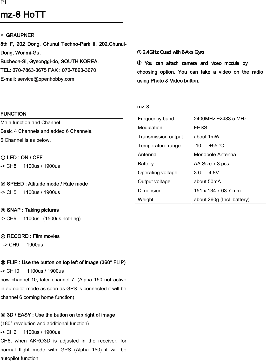
GRAUPNER 16006700 Computer System Graupner HoTT User Manual

GRAUPNER CO., LTD. Computer System Graupner HoTT

User Manual

P1mz-8 HoTT  ◎  GRAUPNER   8th  F,  202  Dong,  Chunui  Techno-Park  II,  202,Chunui-Dong, Wonmi-Gu,   Bucheon-Si, Gyeonggi-do, SOUTH KOREA. TEL: 070-7863-3675 FAX : 070-7863-3670 E-mail: service@openhobby.com    FUNCTION           Main function and Channel Basic 4 Channels and added 6 Channels. 6 Channel is as below.  ① LED : ON / OFF   -> CH8    1100us / 1900us     ② SPEED : Attitude mode / Rate mode       -> CH5    1100us / 1900us     ③ SNAP : Taking pictures        -> CH9    1100us   (1500us nothing)  ④ RECORD : Film movies        -> CH9    1900us          ⑤ FLIP : Use the button on top left of image (360° FLIP) -> CH10    1100us / 1900us     now channel 10, later  channel 7, (Alpha 150 not active in autopilot mode as soon as GPS is connected it will be channel 6 coming home function)    ⑥ 3D / EASY : Use the button on top right of image (180° revolution and additional function)     -> CH6    1100us / 1900us CH6,  when  AKRO3D  is  adjusted  in  the  receiver,  for normal  flight  mode  with  GPS  (Alpha  150)  it  will  be autopilot function           ⑦ 2.4GHz Quad with 6-Axis Gyro             ⑧           You  can  attach  camera  and  video  module  by choosing  option.  You  can  take  a  video  on  the  radio using Photo & Video button.   mz-8                    Frequency band 2400MHz ~2483.5 MHz Modulation FHSS Transmission output about 1mW Temperature range -10 … +55 ℃ Antenna Monopole Antenna Battery AA Size x 3 pcs Operating voltage 3.6 … 4.8V Output voltage about 50mA Dimension 151 x 134 x 63.7 mm Weight about 260g (Incl. battery)
P2 Transmitter manual Operating transmitter  - Power on : Pull Slide switch up - Power off : Pull Slide switch down  1) Flip Function If you push Flip button, buzzer will ring with 0.5 seconds intervals. To rotate a full 360 degrees, push Flip button and when buzzer  starts  ringing,  move  stick  of  transmitter  to maximum position quickly. 2) 3D & Easy Function When you push 3D button, buzzer will ring twice with 1 second intervals. 3D  function  is  for  180  degrees  flight.  To  operate,  use same function with Flip. 3) Attitude Function When you push Function button, one short sound rings. This function is attitude control of general quad copters. 4) Rate Function When you push Function button, two short sound rings. You can do rotation and normal flight on 3D flight mode with transmitter. Function is same with 3D helicopter.      Flip Button  Speed Button  Light Button  3D / Easy Button  Power Switch Status  &  Function Led Camera Record Button Camera  Snep Button MZ-8 Trim Trim
P3 LED Function           < LED arrangement of transmitter >  1) LIGHT ON / OFF Function         Yellow Led   ① When the lights are off, LED stay OFF condition. ② When the lights are on, LED stay ON condition.    (default status)  2) SPEED Attitude and Rate Function Red Led        ①  Attitude  mode  :  LED  stay  ON  condition.(default status)         ② Rate mode :    LED blinks with one second intervals.  3) Camera function    (Optional feature)      Green Led ① When power is switched on, stay On condition.     --> Photograph mode  (default status)   ② When  movie  button is  pressed,  LED  blinks  with one second intervals. --> Video mode         4) Binding and Transmitter status function.     Red Led  (Status Led) ① Show Power and Binding   ② If device is not bound, LED blinks with 0.5 second intervals.     ③ If device is bound, LED stay ON condition.            Status Discription Red LED Green LED Buzzer Bind range Bind status (No bind) blinking (1s)  low beep(1) Bind Success, on  low beep(2) RX receive OK on   Range Test fast blinking  low beep(2) /2sec Error Low Voltage fast blinking  High beep(4) /2sec Sensor Warring   High beep(3) /2sec Rx Voltage, Temp Error fast blinking  High beep(2) /2sec Receive rate low, No RX slow blinking  High beep(1) /2sec Factory Error   Low beep(1) /2sec     Normal mode Trim inc/dec   low beep(1) /click Trim 0%   High beep(1) /click     Program mode Program mode start 1 blink  low beep(1) Program mode exit   low beep(1) Servo Reverse (Normal)  1 blink (5times) low beep(1) Servo Reverse (Reverse)  2 blink (5times) low beep(2) ATV 100%   High beep(1)     Fail Safe mode start 2 blink  low beep(2) Fail safe (trim dn, hold)  1 blink (5times) low beep(1) Fail safe (trim up, fail)  2 blink (5times) High beep(1)     Stick Calibration Calibration mode start 3 blink   Stick move done 3 blink (3times) 3 blink (3times) low beep(2) Dead range set  Dead blink/3sec
P4 Normal Mode (1) Basic Operation - When Power on, the last used memory will be bound to Receiver. -  In  case  of  No  Receiver  connection,  if  you  press  the button of left stick for 1sec, it will search Receiver. - if Receiver is not searched, it will be repeated until find Receiver,  and  you  can  bind  with  new  Receiver  by pressing BIND/LED Switch.    (2) BIND mode In case of no having receiver, which is already saved in memory,  then  you  can  bind  with  new  receiver  by pressing BIND Switch. If Receive Signal is normal, RED LED will be turned On. In  case  of  Waiting  Receiver  or  Range  warning,  RED LED will be slow blinked.  (3) Range Test mode Functional  switch:    Press  shortly  button  of  SPEED  + SNAP once. After  Binding  with  Receiver,  if  you  shortly  press  this functional  Switch,  Range  Test  mode  will  operate  for 90sec. While  operating  Range  mode,  if  you  shortly  press  this switch, Range test mode will be ended. At  Range  mode  operation,  RED  LED  will  blink  quickly and make buzzer sound.   After 90sec, Beep sound will be occurred one time, and enter to Main Mode.  (4) Low Battery Voltage warning RED LED will do fast blinking. ( RED LED indicate State) At  under  3200V,  Warning  will  be  announced  and  at 3300V, warning will be removed. 3Cell Alkaline Battery will be used.  Important Point : While Binding, Transmitter should always have distance from the Receiver. At least 1m should have. Otherwise, it might be connected to Return channel, and do malfunction.  Program Mode (workable only at Binding condition) (1) Condition of Basic Operation Enter  to  Program  mode  :  Press  two  Stick  Switch simultaneously for 2sec.    Release  Program  mode  :  Press  two  Stick  Switch simultaneously for a second.  Indication of Program mode :    Red Led will be blinked once per a second interval .  Program mode : Blink once per a second interval  (2) Saving Data 50pcs of last used Data could be saved.      (3) Adjustment of Servo End Position In case of Stick Calibration, Default will be 100%. At this value, Customer can adjust trim as below way. - 100% --> 1100us ~ 1900us At Max. or Min. Position of Stick, adjust Trim Switch Range of Trim is available 0% ~ 100% ~ 150%. If  move  to  100%  position,  High  Beep  sound  will  be occurred once.    - Red Led will be blinked once per a second interval    Program mode : Blink once per a second interval  (4) Servo Reverse Set This is used when change Servo direction. All  sticks  are  on  neutral  position,  and  move  the  trim switch to Max. or Min. Position. If press Power switch with pressed trim switch to Max. or Min.  position,  Normal  mode  and  Reverse  mode  will  be changed. -  Indication  of  Servo  Receiver  mode  :  Red  Led  will  be blinked once per a second interval - Normal mode : Green LED will be blinked once per a second interval.
P5 -Reverse mode : Green LED will be blinked twice per a second interval.  Program mode : Blink once per a second interval         Normal  mode  :  Blink  once  per  a  second  interval (Repetition 5times) Reverse  mode  :  Blink  twice  per  a  second  interval (Repetition 5times)  (5) Fail Safe Set Press right stick switch for a second at Program mode. Press trim button per channels and select Fail pos mode and Hold it.   Whenever  press  Trim  button,  Setting-condition  will  be transferred to Receiver. If press right-stick switch for a second, Fail safe setting mode will be ended. - Indication of Fail Safe mode : RED LED will be blinked twice per a second interval.   - Pos mode :    If Trim is UP, it is a Fail safe mode, and Green LED  will  be  blinked  twice  per  a second  interval. (Repetition 5times)   - Hold mode :    If Trim is Down, it is a Hold mode, and Green LED will be blinked once per a second interval. (Repetition 5times)   Program  mode  (Failsafe  mode):  Blink  twice  per  a second interval     Hold mode : Blink once per a second interval (Repetition 5times) Pos mode : Blink twice per a second interval (Repetition 5times)       How to do Stick Calibration (1) Enter to Stick Calibration Mode Turn On the Radio, in state of pressing left stick switch. If enter to Mode, RED LED will blink 3 times.  Stick  calibration  mode  :  Blink  3  times  per  a  second interval  (2) Set Stick Calibration Move  all  sticks  from  side  to  Side  and  back  to  middle position. After  operated  last  stick,  hold  it  to  middle  position  for 3Seconds. If Set is done, Red and Green LED will blink 3Times at same time.                        Stick calibration mode    Stick move done Blink 3 Times per a second interval  ※  after  that,  it  is  moved  to  Dead  Range  set  mode automatically.    (3) Dead range set This is for keep Neutral position, in case of they have no accurate Neutral value. Dead  range  set  about  Neutral  position,  is  set  by  trim switch up and down. It can be settable from 1 to 6 steps. ( 0, 2, 4, 6, 8, 10% ) ※  in case of Throttle CH1, there is no spring, Do not set.   ( only set for CH2, CH3, CH4 ) Green LED will blink depends on Neutral set steps. For  example,  if  you  set  Dead  range  to  6%,  LED  will   blink 4times per a second interval.                         Dead range mode     Blink 3times per a sec interval.  Dead range set   Blinks depends of setting value (6 steps)   If set is done, press left stick button for 2 sec.
P6 안전규격  (1) KC  인증    Graupner    mz-8 Transmitter KCC인증번호: MSIP-CRM-sjr-16006700    (2) Conformite Europeenne Product(s): Graupner    mz-8 Transmitter,     (3) FCC Information Graupner mz-8 Transmitter FCC ID: SNL-16006700  FCC Statement 1. This device complies with Part 15 of the FCC Rules. Operation is subject to the following two conditions: (1) This device may not cause harmful interference. (2) This device must accept any interference received, including interference that may cause undesired operation.  2. Changes or modifications not expressly approved by the party responsible for compliance could void the user‘s authority to operate the equipment.  •  NOTE This equipment has been tested and found to comply with the limits for a Class B digital device, pursuant to Part 15 of the FCC Rules. These limits are designed to provide reasonable protection against harmful interference in a residential installation. This equipment generates uses and can radiate radio frequency energy and, if not installed and used in accordance with the instructions, may cause harmful interference to radio communications. However, there is no guarantee that interference will not occur in a particular installation.   If this equipment does cause harmful interference to radio or television reception, which can be determined by turning the equipment off and on, the user is encouraged to try to correct the interference by one or more of the following measures: - Reorient or relocate the receiving antenna. - Increase the separation between the equipment and receiver. - _Connect the equipment into an outlet on a circuit different from that to which the receiver is connected. - Consult the dealer or an experienced radio/TV technician for help.    •   ◎ Notes on environmental protection This  symbol  on  the  product,  user manual or packaging indicates that this product  must  not  be  disposed  of  with other household waste at the end of its life. It must be handed over to the applicable collection point for the recycling  of  electrical  and  electronic equipment. The  materials  are  recyclable  as  marked.  By  recycling, material reusing or other  forms of scrap  usage you are making  an  important  contribution  to  environmental protection. Batteries  and  accumulators  must  be  removed  from  the device and disposed of at an appropriate collection point. Please  inquire  if  necessary  from  the  local  authority  for the appropriate disposal site.

Navigation menu