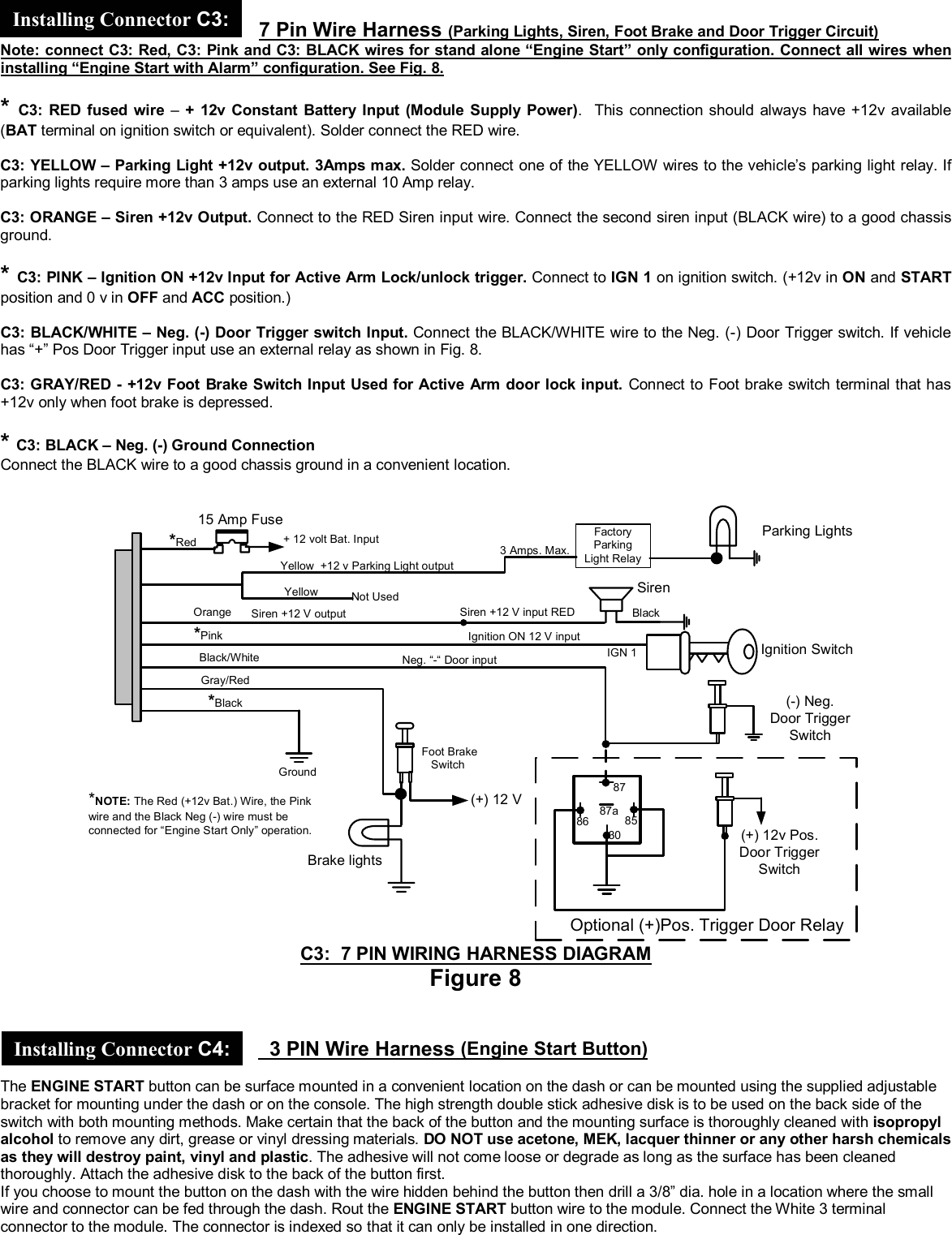
Gallo Technologies GTS10806 GTStarter I User Manual GTStarterI manualfinal060308

Gallo Technologies GTStarter I GTStarterI manualfinal060308

User manual

 © Copyright Gallo Technologies. All Right Reserved                                                                - 1 -                                                                                                                                         52008       Operation & Installation Manual for:    Push Button Start & Alarm System With 2 Remote Key FOBs        DISCLAIMER: This installation manual is designed for the installer or individual with an existing understanding of automotive electrical systems, along with the ability to test and connect wires for proper operation. Some soldering is required. To ease installation, we suggest that you READ THIS MANUAL before beginning your installation. This manual is provided as a GENERAL GUIDELINE and the information contained herein may differ from your vehicle. Gallo Technologies and its’ vendors shall not be liable for any accident resulting from the use of this product. This system is designed to be professionally installed into a vehicle in which all systems and associated components are in perfect working condition. DAMAGE to the  unit resulting from incorrect installation or failure to follow guidelines stated in this manual will not be covered under warranty and will be subject to repair or replacement charges. If you feel after reading the instructions, that you are not adequately skilled to install this product safely please have it professionally installed. Links to nation-wide Audio and Alarm installers can be found on our web site at www.GalloTech.com.   Table of Contents 1.1 Introduction 1.2 Remote Key FOB Operation 1.3   Function Options 1.4 Programming Function Set Up Options 1.5 Installation Instructions     1.6 Final Installation     1.7 Troubleshooting   FCC Compliance This device complies with Part 15 of the FCC Rules. Operation is subject to the following two conditions: (1) this device may not cause harmful interference, and (2) this device must accept any interference received, including interference that may cause undesired operation. www.GalloTech.com
 © Copyright Gallo Technologies. All Right Reserved                                                                - 2 -                                                                                                                                         52008     The  has been designed to function in any vehicle (carbureted, fuel injected, diesel, automatic or manual transmission, and locking or non-locking steering column.) If your vehicle has a factory installed security system with or without an immobilizer, then can be installed without the use of an aftermarket security bypass module, and all of your original security functions will be unaffected. Determine which installation option to use below: Installation Option 1:  can be installed as a full function combined “Engine Start and Alarm System”. If your vehicle comes equipped with an OEM or aftermarket alarm system, installing   as a combined “Engine Start and Alarm System” will require the OEM or aftermarket system to be bypassed by connecting the   wiring harnesses in parallel to the OEM or aftermarket door and alarm function wiring.  If your vehicle is equipped with an OEM electric door lock and unlock only system, then   can be installed by connecting to the OEM door lock/unlock circuitry. When installing   in the “Engine Start and Alarm System” configuration, the supplied key FOBs and siren will be required. See Sec. 1.5 for wiring instructions. Installation Option 2:   can also be installed in a stand alone, “Engine Start,” configuration only (without door locks and alarm functions). In the event that your vehicle has an OEM or a high level security aftermarket alarm system, then   can be installed using the “Engine Start” functions only. Your OEM key FOB will continue to function as it was originally intended.  When installing in the “Engine Start” only configuration, the supplied   key FOBs and siren will not be used. When installing as the “Engine Start” only configuration a number of the   module wires will not be required. Please see installation comments in Sec 1.5  To ease and reduce installation time, we suggest you consider the following points before starting: 1.  Check all vehicle manufacturer cautions and warnings regarding electrical service (AIR BAGS, ABS BRAKES, ENGINE / BODY COMPUTER AND BATTERY). Use extreme care and do not probe any wires of the SRS system. 2.  Additional vehicle specific wiring diagrams and other helpful installation information can be found on our web site at www.GalloTech.com 3.  Determine the most suitable locations for all components to be placed. These components include: The control module , ENGINE START button, siren, supplied relays or possible extra relays. 4.  Use a Volt/Ohm meter to test and locate all connections. Test Lights can damage a vehicle’s computer systems. 5.  Record all color codes of vehicle wiring to be used for reference. This will save time by not having to re-test the same wires over again. Mark all vehicle wires with masking tape. 6.  After locating and marking the appropriate wires DISCONNECT the (+) POS terminal at the battery. 7.  Determine the type of locking system the vehicle has before connecting any wires. Incorrect connection can result in damage to the  and/or vehicle locking system. There are several types of door lock systems in vehicles today. Below is listed the many types of common locking systems: • Negative Trigger (-): Many Imports; Late model Ford & General Motors Negative trigger door lock systems send a Negative (Ground) pulse to existing factory relays to lock and unlock the vehicle doors. • Positive Trigger (+): Many General Motors; Chrysler / Dodge / Plymouth Positive trigger door lock systems send a Positive (+12V) pulse to existing factory relays to lock and unlock the vehicle doors. • Reverse Polarity: Many Ford/Lincoln/Mercury/Dodge/Chrysler/Plymouth and early 90’s GM Trucks The door lock/unlock motors are controlled directly from the lock and unlock switches in the door. The lock and unlock wires rest at Negative Ground when not in use. When the lock or unlock button is pressed, one of the circuits is “Lifted” and replaced with +12V causing a lock or unlock to occur. • Electric vacuum pump: Pre-‘95 Mercedes-Benz and Audi   • Single Wire (Dual Voltage): Late model Chrysler/Dodge/Plymouth Vehicles, some year 2000 and newer GM vehicles Dual Voltage systems have lock/unlock switches that send varying levels of Positive voltage OR Negative ground current to the SAME wire for both lock and unlock. When the vehicle’s Body Computer Module (BCM) or door lock module senses different voltages on this wire, the system will either lock or unlock. Single wire door lock systems require relays and resistors. This type system requires that you have a good working knowledge of their operation before attempting installation of  ’s alarm functions. “Engine Start” only function can be easily installed. • Data bus Systems 2003 and newer GM Trucks/SUV’s, ‘96-04 Jeep Grand Cherokee Data bus systems send low current “Data messages” to the door lock controllers on a network in order to lock and unlock the vehicle. To install aftermarket systems in these vehicles, an interface module is required that converts the regular lock/unlock pulses into “Data messages” to allow locking & unlocking. This type system requires that you have a good working knowledge of their operation before attempting installation of   alarm functions. “Engine Start” only function can be easily installed.        (Lock Button): Arm/Remote- Lock/Panic/Siren-Stop a.)  Arms the system and locks the doors with one press •  Siren will chirp once and parking lights flash once. The blue LED on the Engine Start button will flash slowly. •  The alarm will chirp and parking lights will flash 3 times if all the doors are not closed during arming. You must wait 3 seconds after closing all the doors before the arm button can be pressed to arm the system. •  If the alarm siren has been triggered, pressing this button one time will silence the siren and keep the system in the armed mode. b.) Panic: •  When ignition switch is OFF, holding this button for over 2 seconds will cause the siren to sound for 30 seconds and the system will remain in the armed mode. c.)  Lock only (when vehicle occupied) •  When the ignition key is in the ON position, and the system is disarmed, pressing this button will lock the doors. The system will stay in the disarmed mode. 1.1 INTRODUCTION 1.2 REMOTE KEY FOB OPERATION:
 © Copyright Gallo Technologies. All Right Reserved                                                                - 3 -                                                                                                                                         52008  .    (Unlock Button): Disarm/Remote-Unlock/Release-Anti-hijack. a.)  Disarm the system and unlock the doors with one press •  Siren will chirp twice and the parking lights will flash twice. The green LED on the Engine Start button will flash rapidly. The doors will unlock and the system will be in the disarmed mode. •  Within 30 seconds after pressing the button, if a door is not opened or the ignition key is not turned to the ON position, the system will automatically rearm and relock the doors. •  If the system has been triggered while in the armed mode, the siren will chirp and the parking lights will flash four times, when the unlock button is pressed. b.)  Unlock only (when vehicle occupied) •  When the ignition key is in the ON position, and the system is disarmed, pressing this button will unlock the doors. The system will stay in the disarmed mode. c.) Release Anti-Hijack: •  When the alarm system is in the anti-hijack mode, pressing this button will release the anti-hijacking mode. Mute Button: Mute-(Arm/Disarm)/Remote-Lock/Siren-Stop a.) Mute Arm: • When in disarmed mode press   one time, parking lights flash once, Blue L.E.D. on the Engine Start button will flash slowly, the siren will not chirp, the doors will lock and system will be in armed mode. If a door is not closed when pushing the  button, the siren will chirp and the parking lights will flash 3 times and the system will stay in the armed mode. When the door is closed the system will be in the armed mode. •  Siren stop: When the alarm siren is triggered, pressing the   button or the  button will stop the siren sounding and the system will stay in the armed mode.  Pressing the  button will disarm the system and unlock the doors. b.) Mute Disarm: • When in the armed mode, press   one time then press   will mute the disarm siren. c.)  Lock only by remote: •  When the ignition key is ON, pressing   will lock the doors and the system will remain in the disarmed mode. Siren Button: Car-Locating/Anti-hijack  a.) Car Locating •  When the system is armed, holding this button for more than 2 seconds, the siren will chirp and the parking lights will flash five times. b.)  Anti-Hijack: •  When the ignition key is in the ON position and the system is disarmed, holding this button for over 2 seconds, the parking lights will flash twice. •  After 40 seconds, the siren will chirp (non-continuously) for 20 seconds. After the 20 seconds, the siren will chirp louder (continuously) and the parking lights will flash for another 60 seconds. After the 60 seconds of siren and lights flashing the system will be in the armed mode, and the starter will be disabled. • Pressing the   button will deactivate the Anti-hijacking mode.       The  has numerous user configurable features that can be enabled or modified according to user’s preferences.  This section explains each of the user configurable functions.  See section 1.4 Programming Function Set-Up Options for details on how to modify configurable features. When installing as a stand alone “Engine Start” configuration (without door lock & alarm functions) the only   functions that can be used are those marked with an (*). * Valet Mode:  If Valet Mode is set to ENABLE, pressing  or will lock/ unlock the doors only. All alarm triggers will be disabled. The Green L.E.D. on the Engine Start button will flash for 10 seconds when the ignition is turned from OFF to ON, or ON to OFF.   Transmitter (Key FOB) Code learning: The Key FOBs must be learned by the module before they will function.   Passive Arming:   If Passive Arming is set to ENABLE, the system will automatically arm itself (without locking) 30 seconds after the ignition is turned OFF and a door is opened and then all doors are closed.   1.3   FUNCTION OPTIONS
 © Copyright Gallo Technologies. All Right Reserved                                                                - 4 -                                                                                                                                         52008  Passive Locking:  If Passive Locking is set to ENABLE, the system will automatically lock itself (without arming) 30 seconds after the ignition is turned OFF if a door is opened, and then all doors are closed. If Passive Arming AND Passive Locking are set to ENABLE, the system will automatically arm and lock the doors 30 seconds after the ignition is turned OFF and a door is opened and then all doors are closed. Note: This function could result in the keys/FOB being locked in the vehicle. Use caution when selecting this function. Locking Time:  When pressing   or the electrical pulse sent to the door locking/unlocking mechanism can be set at either 0.4 seconds or 4 seconds. Most cars will function properly when this option is set to the factory default of 0.4 seconds.   Ignition Key door Locking/ Unlocking:  When this option is set to ENABLE the doors will automatically unlock when the ignition key is turned off and the doors will lock when the foot brake is depressed. This function will not activate if a door is open when the ignition key is cycled OFF/ON.   Active Arm & Lock:  If this option is set to ENABLE, the system will automatically rearm and relock itself within 30 seconds after the system is disarmed by pressing  , if the door is not opened or the ignition key is not turned ON.   Lock/Unlock siren Chirp: If this option is set to DISABLE the siren will not chirp when locking and unlocking the doors.  Two Pulse Locking / unlocking:  When pressing   or the electrical pulse sent to the door locking/unlocking mechanism can be set at either one pulse or two pulses. Most vehicles only require one pulse (factory default). Some vehicles require one pulse to unlock the driver’s door only and a second pulse to unlock all doors. If this is the case and you want all doors to be unlocked at the same time, set this option to two pulses. OR, setting to one pulse will unlock the driver’s door on the first unlock button push then unlock all doors on the second push.   * Ignition Key Start Function:  If this option is set to ENABLE (factory default) the vehicle can be started by using either the ignition key or the ENGINE START push button. If this option is set to DISABLE the vehicle can be started with the ENGINE START push button only.   * Disable Start Button Cut Off Delay: If this option is set to ENABLE (factory default) the vehicle can be started after the ignition key is turned ON and there will be no start button cut off delay.   * 30 Second Start Button Cut Off Delay: If this option is set to the vehicle can not be started 30 seconds after the ignition key is turned ON. Recycling the ignition key OFF to ON will reset the time delay for another 30 seconds.   * 60 Second Start Button Cut Off Delay: If this option is set to ENABLE the vehicle can not be started 60 seconds after the ignition key is turned ON. Recycling the ignition key OFF to ON will reset the time delay for another 60 seconds.   * 5 Minutes Start Button Cut Off Delay: If this option is set to ENABLE the vehicle can not be started 5 minutes after the ignition key is turned ON. Recycling the ignition key OFF to ON will reset the time delay for another 5 minutes.   * 10 Minutes Start Button Cut off Delay: If this option is set to ENABLE the vehicle can not be started 10 minutes after the ignition key is turned ON. Recycling the ignition key OFF to ON will reset the time delay for another 10 minutes.          This section explains how to configure the   functions.  See section 1.3 for detailed explanation of each function. 1.  The system must be in DISARM mode, and the Ignition key must be in the OFF position for a minimum of 3 sec. 2.  Cycle the Ignition key OFF/ON 3 times, and keep the ignition key in the ON position the 3rd time. After 3 sec the parking lights will flash 2 times indicating the function setup mode has been activated. 3. Press the ENGINE START button OFF/ON “n” times and on the nth time hold the ENGINE START button in the ON position for 3 sec. The parking lights will flash either 3 times or 1 time indicating the state that the function option has been changed to. 4.  After turning the ignition key to the OFF position, the parking lights will flash 5 times, indicating the Function Set up Mode has been exited. 5.  To change another  function option repeat steps 1 thru 4 above. NOTE: “n” indicates the number of times the ENGINE START button is to be pushed for the respective Function Option in the first column of TABLE 1 below.         1.4 PROGRAMMING FUNCTION SET UP OPTIONS
 © Copyright Gallo Technologies. All Right Reserved                                                                - 5 -                                                                                                                                         52008  Table 1: FUNCTION OPTION CHART Parking lights flash 3 times or 1 time to indicate the function state “Engine Start” button OFF/ON n th times Function To Set Parking lights Flash 3 times Parking Lights Flash 1 time 1 time  * Valet Mode Disable Enable (factory default) 2 times  Key FOB Code learning                                                 Code learning Follow steps 1& 2 above to enter programming mode. Press ENGINE START button OFF/ON 2 times and hold at ON position, After 2 seconds parking lights will flash 2 times to indicate code learning is activated. Then press any button of the transmitter. The parking lights will flash 4 times to indicate the key FOB code has been successfully learned. Each FOB must be programmed. 3 times  Passive arming  Enable  Disable (factory default) 4 times  Passive locking  Enable  Disable (factory default) 5 times  Locking Time  4 sec.  0.4sec (factory default) 6 times  Ignition Key Door locking/unlocking  Enable  Disable (factory default) 7 times  Active Arm & Lock  Enable  Disable (factory default) 8 times  Lock/unlock Siren Chirp  Disable Enable (factory default) 9 times  Two Pulse locking/unlocking  Enable  Disable (factory default) 10 times  * Ignition Key Start Function Disable Enable (factory default) 11 times  * Disable Start Button Cut Off Delay Parking lights flashes 1 time to indicate enabled (factory default) 12 times  * 30 Second Start Button Cut Off Delay Parking lights flashes 1 time to indicate enabled 13 times  * 60 Second Start Button Cut Off Delay Parking lights flashes 1 time to indicate enabled 14 times  * 5 minutes Start Button Cut Off Delay Parking lights flashes 1 time to indicate enabled 15 times  * 10 minutes Start Button Cut Off Delay Parking lights flashes 1 time to indicate enabled * When installing as a stand alone “Engine Start” configuration (without door lock & alarm functions) the only   functions that can be used are those marked with an (*).    When installing as a stand alone “Engine Start” only configuration, the only wires that must be connected are those marked with an (*)      SEE FIG. 1 FOR LOCATION AND IDENTIFICATION OF   CONTROL MODULE CONNECTORS.    1.5 INSTALLATION INSTRUCTIONS
 © Copyright Gallo Technologies. All Right Reserved                                                                - 6 -                                                                                                                                         52008      4 Pin Wire Harness (Engine Start Circuit) All Wires on both connector C1: and R1/R2 relay pair must be connected when installing either Engine Start only or “Engine Start and Alarm” configuration.  See Fig. 2 showing wire configurations for connector C1 and R1/R2 relay pair. * C1:   RED – Start Circuit Supply Power.  The RED wire is used to power the   starting circuitry. Before connecting this wire you must first find the IGN 1 wire coming from the ignition switch. The IGN 1 wire is used to send +12v to the ignition system and engine computer when the ignition switch is in the ON and START position. Solder connect the C1 RED wire to the IGN 1 (ignition/computer) wire coming from the Ignition switch. At the same time that you connect the C1: RED wire, also solder connect the PINK wire from connector C3. Do not cut the IGN1 wire. * C1: ORANGE – Key Start Module Output. Before connecting this wire you must first find the START wire coming from the ignition switch. The START wire is used to send +12v through the Park/Neutral safety switch (automatic transmission) to the starter solenoid. After identifying the wire it must be cut near the ignition switch terminal.  Insure that you DO NOT by-pass the Park / Neutral switch; otherwise the engine could be started while in Drive or Reverse.   After cutting the START wire in the appropriate place solder connect the C1: ORANGE wire to the cut START wire closest to the ignition switch terminal.    * C1:  BLUE – Engine Start Output The C1: BLUE wire directly sends a +12 v signal from the   module to the starter solenoid (and through the Park/Neutral switch) when the system is disarmed, the ignition switch is in the ON position, and the ENGINE START button is pushed. Solder connect the C1: BLUE wire to the other cut end of the START wire. At the same time that you connect the C1: BLUE wire, also solder connect the RED fused wire from the supplied relay pair (R1 & R2).     Accessory Disconnect Relay Pair (Engine Start Circuit) * R1/R2: ORANGE (2 wires)– Heater, A/C Blower, etc Engine Start Disconnect. Locate the Heater, A/C blower wire coming from the ignition switch. This wire should have +12v only when the ignition key is in the ON position. When the key is turned to the OFF, ACC, or START position there should be 0 v. Cut this wire and solder connect the two ORANGE wires to the two cut ends. The R1/R2: ORANGE wires are interchangeable and can be connected to either of the cut ends of the Ignition Switch ON wire. * R1/R2: RED fused wire – Accessory Disconnect Relay Activation Circuit Connect the fused RED wire as per C1: BLUE – Engine Start Output in Fig. 2. R1/R2: BROWN (2 wires) - Radio, Wiper, etc. Engine Start Disconnect Locate the Radio, Wiper, etc.  wire coming from the ignition switch. This wire should have +12v only when the ignition key is in the ON and ACC positions. When the key is turned to the OFF, or START position there should be 0 v. Cut this wire and solder connect the two BROWN wires to the two cut ends. The R1/R2: BROWN wires are interchangeable and can be connected to either of the cut ends of the Ignition switch ACC wire. * R1/R2: BLACK – Neg. (-) Ground Connection Connect the BLACK wire to a good chassis ground in a convenient location.  NOTE: Do not cut any wires to the Ignition /computer wires from the ignition switch. Some vehicles have 1 or 2 separate ignition wires. These wires will have +12v in the ON and START positions and 0 v in the OFF and ACC positions.      Figure 1 *InstallingConnector C1:* Installing Relays R1/R2:
 © Copyright Gallo Technologies. All Right Reserved                                                                - 7 -                                                                                                                                         52008   C1, R1/R2:  4 PIN WIRE HARNESS and RELAY PAIR (Engine Start Circuit) Figure   2    6 Pin Wire Harness (Door Lock/Unlock Circuit) Used for “Engine Start with Alarm” configuration only Determine the Door Locking/Unlocking circuitry that your vehicle is equipped with.  Fig. 3 shows the door lock/unlock output relay configuration of the  . The majority of vehicles come equipped with either  Neg.(-) Fig. 4 or  Pos.(+) Fig. 5 Trigger circuits. Find the location of the appropriate circuitry for your vehicle (Make, Model, Year Diagrams can be found on our web site at www.GalloTech.com) If the Trigger wire is 0v when the Lock/unlock switch is depressed then you have a Neg. (-)  trigger (Fig. 4). If the trigger wire is +12v when depressing the Lock/unlock switch then you have a Pos.(+) Trigger (Fig 5). For Pre- ’95 Audi or Mercedes Benz vacuum motor operation use Fig. 6. For Reverse Polarity applications, were the lock and unlock wires rest at Negative Ground,  use Fig. 7.  C2:  6 PIN WIRE HARNESS DIAGRAMS: Door Locking/Unlocking Circuits  NORMAL DOOR LOCK/UNLOCKOUTPUT CONFIGURATIONGreen/RedGreen/WhiteGreen/YellowBlue/RedBlue/WhiteBlue/YellowNormally Closed (NC-1)COMMON (1)Normally Open (NO-1)COMMON (2)LOCKOUTPUTUNLOCKOUTPUTNormally Closed (NC-2)Normally Open (NO-2)  Figure 3   Installing Connector C2:
 © Copyright Gallo Technologies. All Right Reserved                                                                - 8 -                                                                                                                                         52008   Figure 4   Figure 5                                  Figure 6  Figure   7
 © Copyright Gallo Technologies. All Right Reserved                                                                - 9 -                                                                                                                                         52008      7 Pin Wire Harness (Parking Lights, Siren, Foot Brake and Door Trigger Circuit)  Note: connect C3: Red, C3: Pink and C3: BLACK wires for stand alone “Engine Start” only configuration. Connect all wires when installing “Engine Start with Alarm” configuration. See Fig. 8.  * C3: RED fused wire –  + 12v Constant Battery Input (Module Supply Power).  This connection should always have +12v available (BAT terminal on ignition switch or equivalent). Solder connect the RED wire.   C3: YELLOW – Parking Light +12v output. 3Amps max. Solder connect one of the YELLOW wires to the vehicle’s parking light relay. If parking lights require more than 3 amps use an external 10 Amp relay.  C3: ORANGE – Siren +12v Output. Connect to the RED Siren input wire. Connect the second siren input (BLACK wire) to a good chassis ground.  * C3: PINK – Ignition ON +12v Input for Active Arm Lock/unlock trigger. Connect to IGN 1 on ignition switch. (+12v in ON and START position and 0 v in OFF and ACC position.)  C3: BLACK/WHITE – Neg. (-) Door Trigger switch Input. Connect the BLACK/WHITE wire to the Neg. (-) Door Trigger switch. If vehicle has “+” Pos Door Trigger input use an external relay as shown in Fig. 8.   C3: GRAY/RED - +12v Foot Brake Switch Input Used for Active Arm door lock input. Connect to Foot brake switch terminal that has +12v only when foot brake is depressed.  * C3: BLACK – Neg. (-) Ground Connection Connect the BLACK wire to a good chassis ground in a convenient location.  YellowYellowOrange*PinkBlack/WhiteGray/Red*Black+ 12 volt Bat. Input+12 v Parking Light outputSiren +12 V outputIgnition ON 12 V inputNeg. “-“ Door input Foot BrakeSwitchGroundNot Used(+) 12 VBrake lights(-) Neg.Door TriggerSwitchSiren15 Amp Fuse Parking LightsIGN 1 Ignition Switch*Red*NOTE: The Red (+12v Bat.) Wire, the Pinkwire and the Black Neg (-) wire must beconnected for “Engine Start Only” operation.3 Amps. Max.FactoryParkingLight Relay87863087a 85(+) 12v Pos.Door TriggerSwitchOptional (+)Pos. Trigger Door RelaySiren +12 V input RED Black C3:  7 PIN WIRING HARNESS DIAGRAM Figure 8     3 PIN Wire Harness (Engine Start Button)  The ENGINE START button can be surface mounted in a convenient location on the dash or can be mounted using the supplied adjustable bracket for mounting under the dash or on the console. The high strength double stick adhesive disk is to be used on the back side of the switch with both mounting methods. Make certain that the back of the button and the mounting surface is thoroughly cleaned with isopropyl alcohol to remove any dirt, grease or vinyl dressing materials. DO NOT use acetone, MEK, lacquer thinner or any other harsh chemicals as they will destroy paint, vinyl and plastic. The adhesive will not come loose or degrade as long as the surface has been cleaned thoroughly. Attach the adhesive disk to the back of the button first. If you choose to mount the button on the dash with the wire hidden behind the button then drill a 3/8” dia. hole in a location where the small wire and connector can be fed through the dash. Rout the ENGINE START button wire to the module. Connect the White 3 terminal connector to the module. The connector is indexed so that it can only be installed in one direction.  Installing Connector C4: Installing Connector C3:
 © Copyright Gallo Technologies. All Right Reserved                                                                - 10 -                                                                                                                                         52008      1.  Recheck all electrical connections to be certain they are connected in the proper locations and check that all connections are wrapped with a good quality electrical tape or shrink tubing. 2.  Connect all 4 module connectors to the module. The module should be secured under the dash using cable ties or equivalent. 3.  Attach the R1/R2 relay pair under the dash and secure with cable ties or equivalent as needed. 4.  Reconnect the battery and thoroughly test all starting functions. Make certain that the vehicle can not be started while it is in any gear except Neutral and/or Park (automatic transmission). 5.  Code learn the key FOBs first.  The alarm functions will not function until the key FOBs have been taught to the module.  6.  Program the module to the functions that you desire following Sec. 1.4 “Programming Function Set Up Options” and Table 1.      ENGINE CRANKS BUT WILL NOT START: Check Ignition switch wiring. The IGN 1 wire must not be cut. The only   wires connected to this wire should be the RED Start Input +12 v from connector C1 and the C3 PINK wire. Some vehicles require 2 separate ignition wires for the vehicle’s ignition system to function properly. Make sure both of these ignition wires have not been cut. ENGINE STARTS IN DRIVE OR REVERSE GEAR (AUTOMATIC TRANSMISSION). Check the location of ORANGE (Key Start Input) and BLUE (Start Engine Output) wires. They MUST be connected to the vehicles start wire close to the ignition switch, making certain that the Park/Neutral lockout is not bypassed. AN ACCESSORY (RADIO, HEATER FAN, ETC.) DOES NOT TURN OFF DURING ENGINE CRANKING AND/OR TURN BACK ON AFTER CRANKING: a.) R1/R2 Relays have not been connected to the correct Ignition switch wires.  There are usually only two positions on the ignition switch which disconnect power to the accessories during engine cranking.  Check the specific wiring diagrams for your Make, Model, and Year vehicle.  b.) Check the RED +12v from R1/R2 relay pair. It must be connected to the BLUE (Start Engine Output) C1: wire. Also check the BLACK R1/R2 wire making certain that it is connected to a good chassis ground. c.) Check the 10 Amp fuse. If it is blown then there must be a short somewhere along the RED R1/R2 wire. DOORS LOCK/UNLOCK WHEN THEY SHOULD UNLOCK/LOCK: Connector C2: 6 Pin Wire Harness wires have been incorrectly connected to the vehicles Master Lock switch. Reverse the wires.    1.6 FINAL INSTALLATION 1.7 TROUBLESHOOTING INSTALLATION NOTES

Navigation menu