Gallo Technologies GTS20210 GTSTARTER2 User Manual GTS2 Operation manual final
Gallo Technologies GTSTARTER2 GTS2 Operation manual final
UserManual.wiki
>
Gallo Technologies
>
GTS20210 User Manual
Users Manual
Navigation menu
Upload a User Manual
Namespaces
Wiki Guide
HTML
PDF
Info
Views
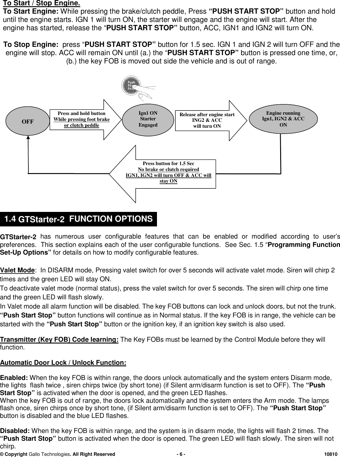
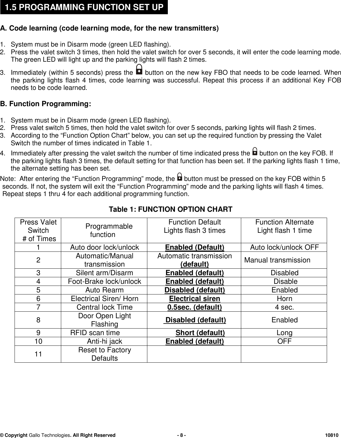
User Manual
Discussion / Help
Navigation