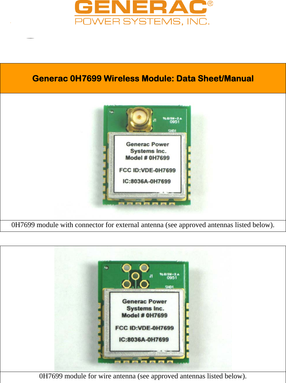
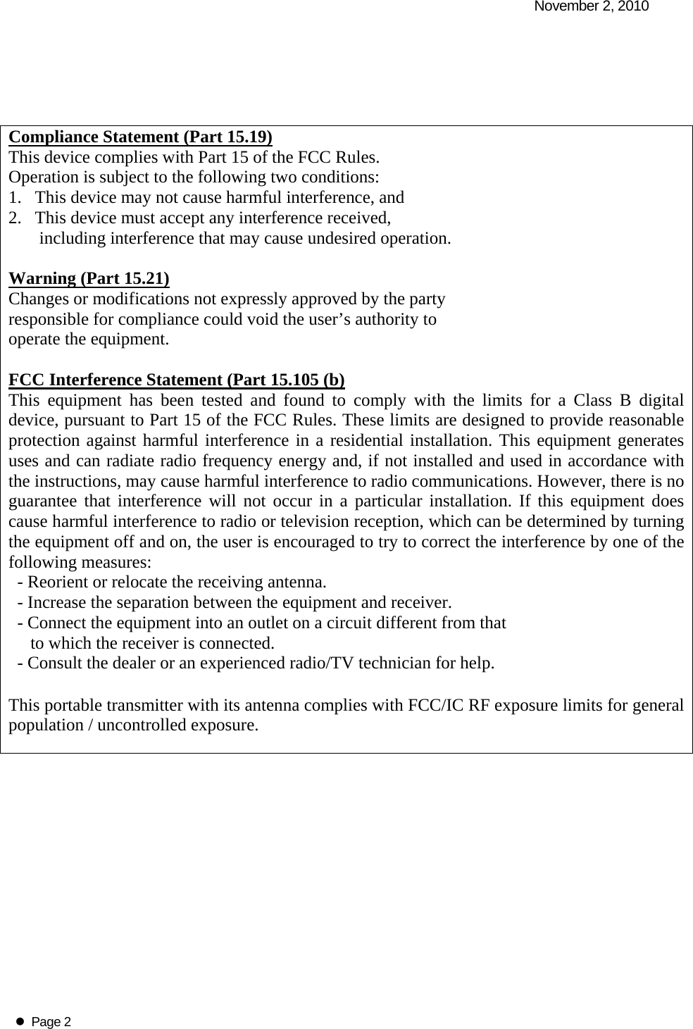
Generac Power Systems 0H7699 Generator Monitor Module User Manual Module Data Sheet V1

Generac Power Systems Generator Monitor Module Module Data Sheet V1

Manual

                                                                                                                   Generac 0H7699 Wireless Module: Data Sheet/Manual   0H7699 module with connector for external antenna (see approved antennas listed below).  0H7699 module for wire antenna (see approved antennas listed below).
  November 2, 2010   Page 2     Compliance Statement (Part 15.19) This device complies with Part 15 of the FCC Rules.  Operation is subject to the following two conditions:  1.   This device may not cause harmful interference, and  2.   This device must accept any interference received,         including interference that may cause undesired operation.  Warning (Part 15.21) Changes or modifications not expressly approved by the party  responsible for compliance could void the user’s authority to  operate the equipment.  FCC Interference Statement (Part 15.105 (b) This equipment has been tested and found to comply with the limits for a Class B digital device, pursuant to Part 15 of the FCC Rules. These limits are designed to provide reasonable protection against harmful interference in a residential installation. This equipment generates uses and can radiate radio frequency energy and, if not installed and used in accordance with the instructions, may cause harmful interference to radio communications. However, there is no guarantee that interference will not occur in a particular installation. If this equipment does cause harmful interference to radio or television reception, which can be determined by turning the equipment off and on, the user is encouraged to try to correct the interference by one of the following measures:   - Reorient or relocate the receiving antenna.   - Increase the separation between the equipment and receiver.   - Connect the equipment into an outlet on a circuit different from that        to which the receiver is connected.   - Consult the dealer or an experienced radio/TV technician for help.  This portable transmitter with its antenna complies with FCC/IC RF exposure limits for general population / uncontrolled exposure.
  November 2, 2010   Page 3   Section 7.1.5 of RSS-GEN Operation is subject to the following two conditions:  1) this device may not cause interference, and 2) this device must accept any interference,       including interference that may cause undesired operation of the device.  Section 7.1.4 of RSS-GEN This device has been designed to operate with the antenna(s) listed below, and having a maximum gain of 2.0 dB.  Antennas not included in this list or having a gain greater than 2.0 dB are strictly prohibited for use with this device.  The required antenna impedance is 50 ohms.  List of all Antennas Acceptable for use with the Transmitter  20AWG Insulated tinned-Cu wire 3.82in (97.0mm). Nearson S467AH-915 (SMA rev polarity).  Section 7.1.5 of RSS-GEN To reduce potential radio interference to other users, the antenna type and its gain should be so chosen that the equivalent isotropically radiated power (e.i.r.p.) is not more than that permitted for successful communication.     Federal Communication Commission Interference Statement This equipment has been tested and found to comply with the limits for a Class B digital device, pursuant to Part 15 of the FCC Rules. These limits are designed to provide reasonable protection against harmful interference in a residential installation. This equipment generates uses and can radiate radio frequency energy and, if not installed and used in accordance with the instructions, may cause harmful interference to radio communications. However, there is no guarantee that interference will not occur in a particular installation. If this equipment does cause harmful interference to radio or television reception, which can be determined by turning the equipment off and on, the user is encouraged to try to correct the interference by one of the following measures:  -  Reorient or relocate the receiving antenna. -  Increase the separation between the equipment and receiver. - Connect the equipment into an outlet on a circuit different from that     to which the receiver is connected. -  Consult the dealer or an experienced radio/TV technician for help.
  November 2, 2010   Page 4 This device complies with Part 15 of the FCC Rules. Operation is subject to the following two conditions: (1) This device may not cause harmful interference, and (2) this device must accept any interference received, including interference that may cause undesired operation.  FCC Caution: Any changes or modifications not expressly approved by the party responsible for compliance could void the user's authority to operate this equipment.  INDUSTRY CANADA STATEMENTS  Operation is subject to the following two conditions: (1) this device may not cause interference, and (2) this device must accept any interference, including interference that may cause undesired operation of the device.  To reduce potential radio interference to other users, the antenna type and its gain should be so chosen that the equivalent isotropically radiated power (e.i.r.p.) is not more than that permitted for successful communication.  This device has been designed to operate with the antennas listed below, and having a maximum gain of 2.0 dB. Antennas not included in this list or having a gain greater than 2.0 dB are strictly prohibited for use with this device. The required antenna impedance is 50 ohms.   List of all Antennas Acceptable for use with the Transmitter   20AWG Insulated tinned-Cu wire 3.82in (97.0mm).  Nearson S467AH-915 (SMA rev polarity).  OEM Responsibilities to comply with FCC and Industry Canada Regulations  The 0H7699 Module has been certified for integration into products only by OEM integrators under the following conditions:   1. The transmitter module must not be co-located or operating in conjunction with any other antenna or transmitter.   As long as the two conditions above are met, further transmitter testing will not be required. However, the OEM integrator is still responsible for testing their end-product for any additional compliance requirements required with this module installed (for example, digital device emissions, PC peripheral requirements, etc.).  IMPORTANT NOTE: In the event that these conditions cannot be met (for certain configurations or co-location with another transmitter), then the FCC and Industry Canada authorizations are no longer considered valid and the FCC ID and IC
  November 2, 2010   Page 5 Certification Number cannot be used on the final product. In these circumstances, the OEM integrator will be responsible for re-evaluating the end product (including the transmitter) and obtaining a separate FCC and Industry Canada authorization.  End Product Labeling The 0H7699 Module is labeled with its own FCC ID and IC Certification Number. If the FCC ID and IC Certification Number are not visible when the module is installed inside another device, then the outside of the device into which the module is installed must also display a label referring to the enclosed module.  In that case, the final end product must be labeled in a visible area with the following:   “Contains Transmitter Module FCC ID: VDE-0H7699” “Contains Transmitter Module IC: 8036A-0H7699” or  “Contains FCC ID: VDE-0H7699”  “Contains IC: 8036A-0H7699”   The OEM of the 0H7699 Module must only use the approved antenna(s) listed above, which have been certified with this module.  The OEM integrator has to be aware not to provide information to the end user regarding how to install or remove this RF module or change RF related parameters in the user manual of the end product.
  November 2, 2010   Page 6  Specifications   Performance: Operating Frequency  ISM Band 902-928MHz Outdoor RF line-of-sight range  External dipole antennas: 430 ft (131 m) Outdoor to Indoor (through wall) range  100 ft to wall, 100 ft inside building (typical). Range inside building will vary according to:  Distance of outdoor transceiver from outdoor/indoor interface (wall).  Type of interface i.e. brick, aluminum siding, stone, tinted windows using metalized tint.  Orientation of transceiver antennas (to each other).   Number and type of internal walls, between transceivers, within building.   Transmit Power Output  Internal antenna: -2.8 dBm External dipole antenna -5.3 dBm Throughput Data rate  2400 baud Receiver Sensitivity  -102 dBm   Power Requirements: Supply Voltage (Regulated)  3 ± 0.15Vdc Receive Current  13.6mA Transmit Current  25.4mA Standby Current  < 500nA   General: Dimensions  1.25in x 1.05in x 0.16in (32.0mm x 26.5mm x 4.2mm) Weight   without SMA connector  0.2oz (6g) with SMA connector  0.3oz (9g)  Antenna Options  without SMA connector  Insulated tinned-Cu wire 3.82in (97.0mm), stripped 0.12in (3.0mm). with SMA connector  Nearson S467AH-915 (SMA rev polarity) Operating Temperature  -40°C to +85°C   Agency Approvals: FCC Part 15.249  VDE-0H7699 Industry Canada (IC)  8036A-0H7699

Navigation menu