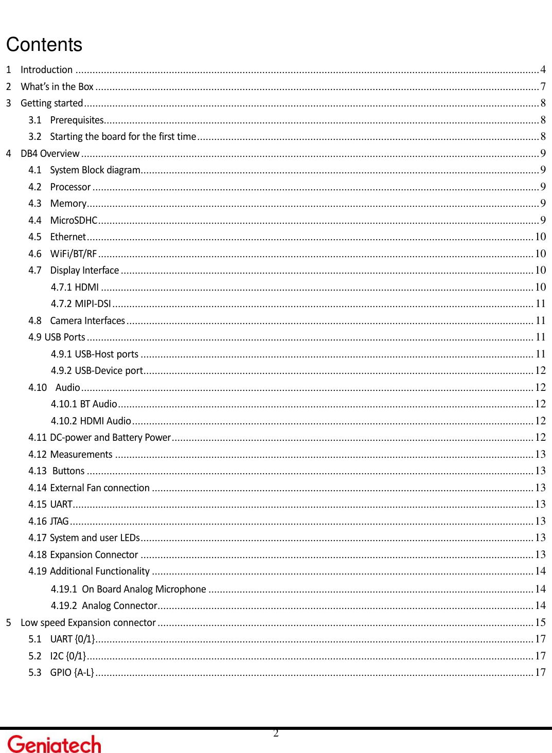
Geniatech 17D11C6 Developer Board User Manual Hardware Manual
Shenzhen Geniatech INC.,LTD. Developer Board Hardware Manual
UserManual.wiki
>
Geniatech
>
17D11C6 User Manual
User Manual
Navigation menu
Upload a User Manual
Namespaces
Wiki Guide
HTML
PDF
Info
Views
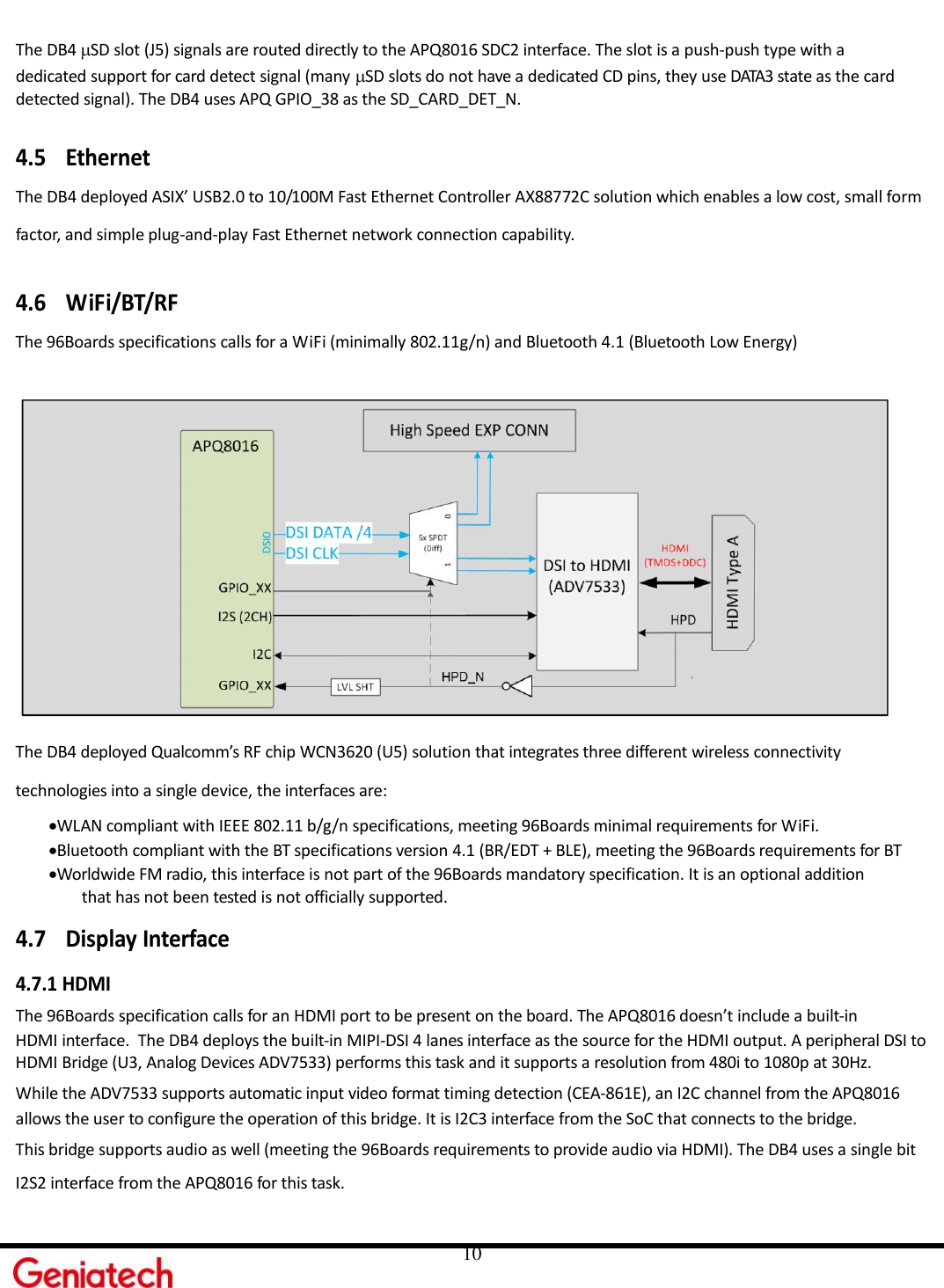
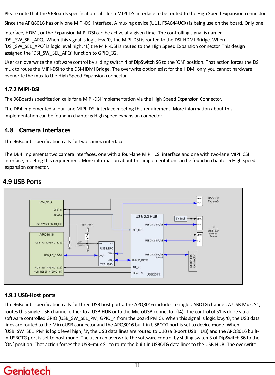
User Manual
Discussion / Help
Navigation