Gongjin Electronics PI699E23 200Mbps PLC Wallmount User Manual V4VPI699E23
Shenzhen Gongjin Electronics Co., Ltd 200Mbps PLC Wallmount V4VPI699E23
UserManual.wiki
>
Gongjin Electronics
>
PI699E23 User Manual
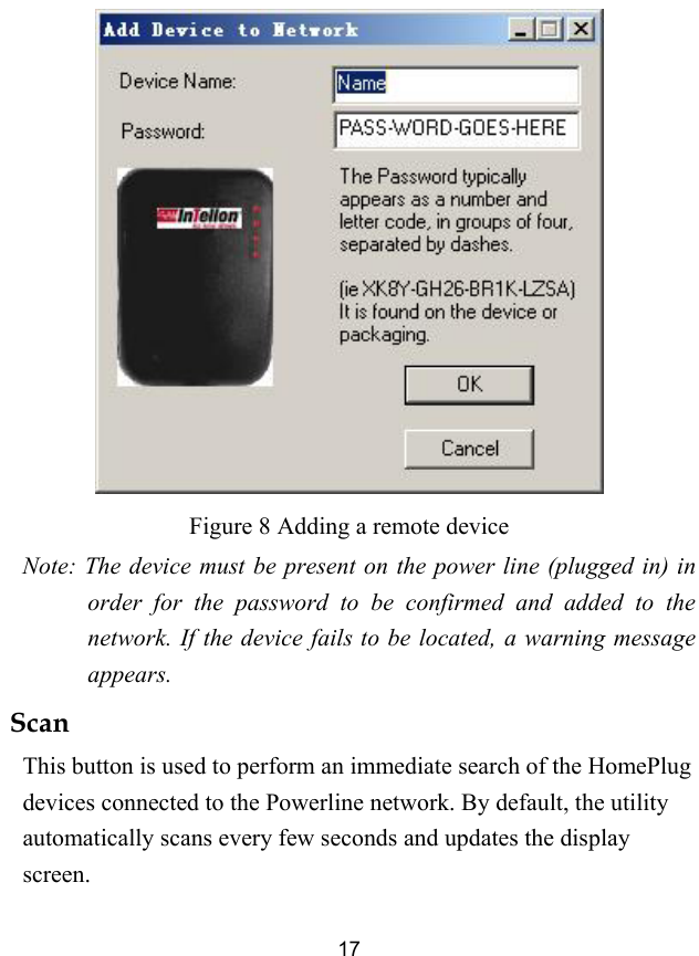
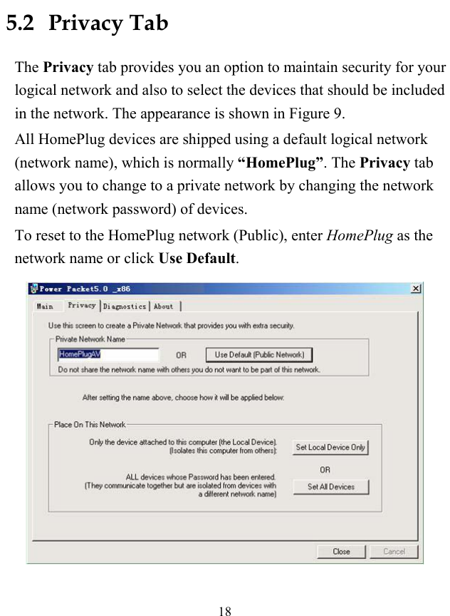
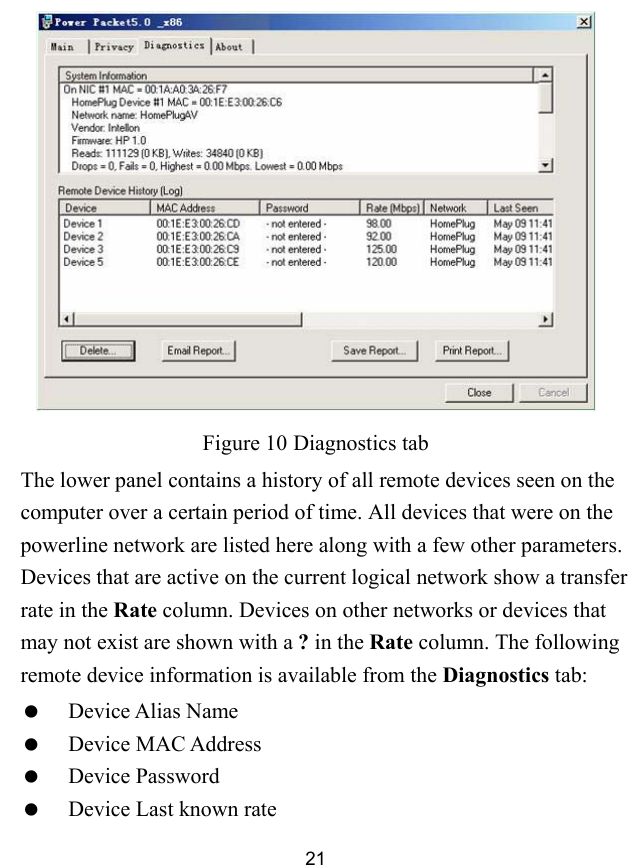
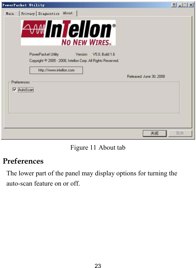
Users Manual
Navigation menu
Upload a User Manual
Namespaces
Wiki Guide
HTML
PDF
Info
Views
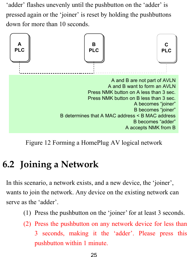
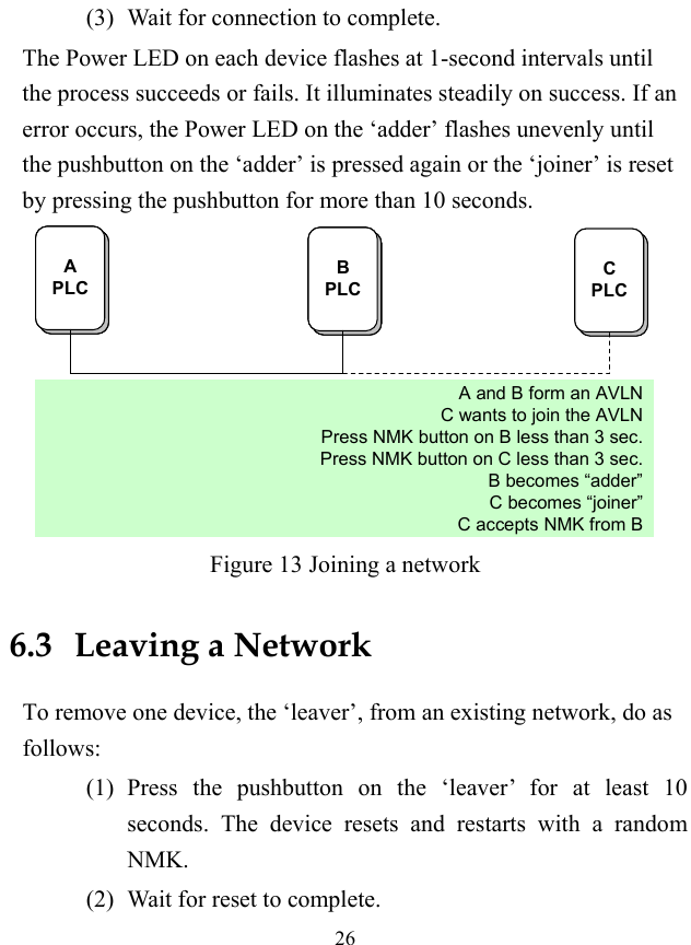
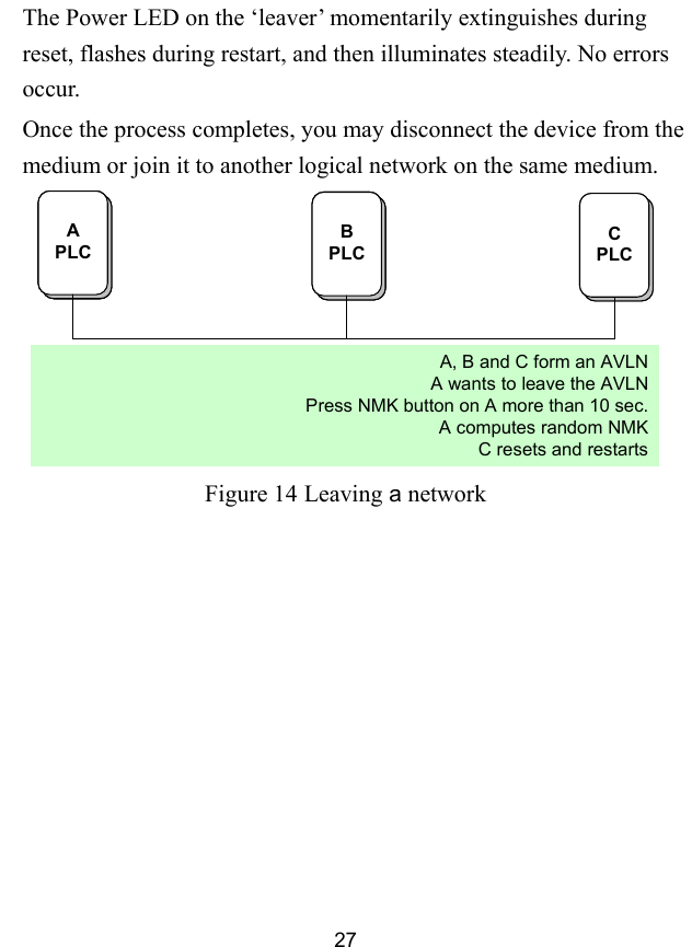
User Manual
Discussion / Help
Navigation