Grayhill EZCOMWL24IP Wireless LAN Router User Manual EZCom IP Users Manual A6
Grayhill Inc Wireless LAN Router EZCom IP Users Manual A6
Grayhill >
Contents
- 1. User manual for product
- 2. Page 2 of user manual
- 3. page 2 of manual with RF exposure info
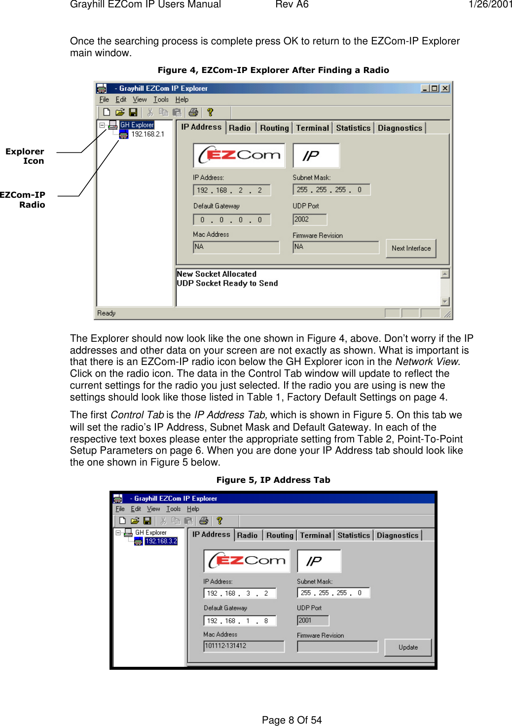
User manual for product
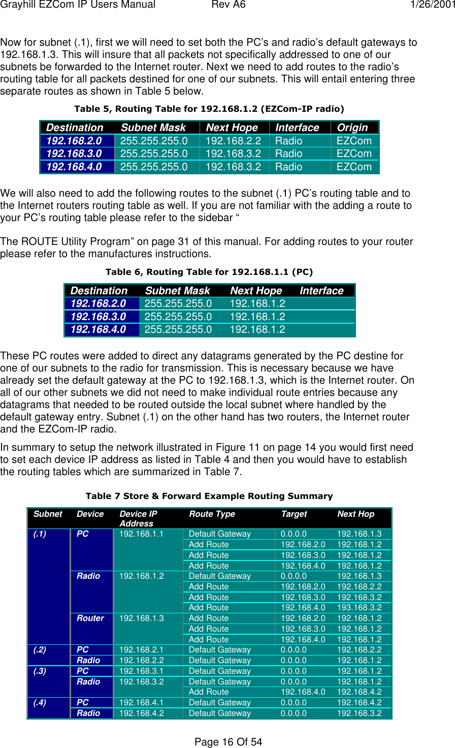
![Grayhill EZCom IP Users Manual Rev A6 1/26/2001Page 31 Of 54The ROUTE Utility ProgramSyntax for the ROUTE command is as follows:Manipulates network routing tables.ROUTE [-f] [command [destination] [MASK netmask] [gateway] [METRIC metric]]-f Clears the routing tables of all gateway entries. If this is used in conjunction withone of the commands, the tables are cleared prior to running the command.-p When used with the ADD command, makes a route persistent across boots ofthe system. By default, routes are not preserved when the system is restarted.When used with the PRINT command, displays the list of registered persistentroutes. Ignored for all other commands, which always affect the appropriatepersistent routes.command Specifies one of four commandsPRINT Prints a routeADD Adds a routeDELETE Deletes a routeCHANGE Modifies an existing routedestination Specifies the host.MASK If the MASK keyword is present, the next parameter is interpreted as thenetmask parameter.netmask If provided, specifies a sub-net mask value to be associated with thisroute entry. If not specified, it defaults to 255.255.255.255.gateway Specifies gateway.METRIC specifies the metric/cost for the destinationAll symbolic names used for destination are looked up in the network database fileNETWORKS. The symbolic names for gateway are looked up in the host name databasefile HOSTS.If the command is print or delete, wildcards may be used for the destination and gateway,or the gateway argument may be omitted.](https://usermanual.wiki/Grayhill/EZCOMWL24IP.User-manual-for-product/User-Guide-134141-Page-31.png)
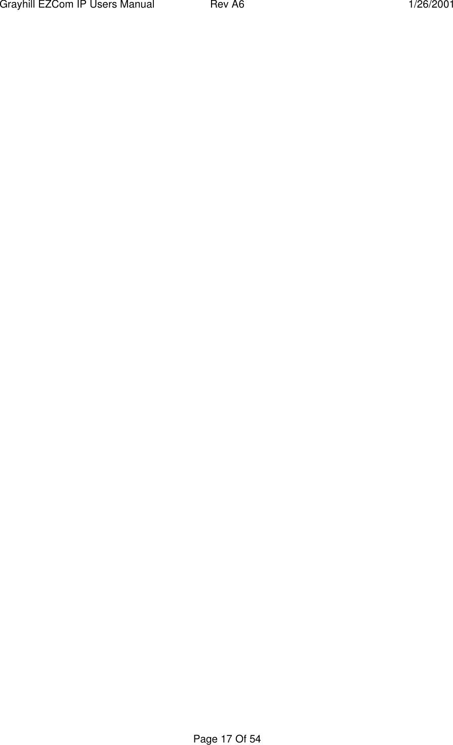
![Grayhill EZCom IP Users Manual Rev A6 1/26/2001Page 33 Of 54This might seem a little severe. Entries in the ARP cache, however, are the hardwareaddresses of the network cards in other hosts. This could very possibly change for agiven host, and would (if your entries were permanent) require all the hosts to beupdated.ARP Utility ProgramTo work with your ARP cache, you can use the ARP command. You can use ARP todisplays and modify the IP-to-Physical address translation tables used by the addressresolution protocol (ARP).The following is the help text for the ARP command:C:\users\default>arp /? ARP -s inet_addr eth_addr [if_addr] ARP -d inet_addr [if_addr] ARP -a [inet_addr] [-N if_addr]-a Displays current ARP entries by interrogating the current protocol data. Ifinet_addr is specified, the IP and Physical addresses for only the specifiedcomputer are displayed. If more than one network interface uses ARP, entries foreach ARP table are displayed.-g Same as -a.inet_addr Specifies an internet address.-N if_addr Displays the ARP entries for the network interface specified by if_addr.-d Deletes the host specified by inet_addr.-s Adds the host and associates the Internet address inet_addr with the Physicaladdress eth_addr. The Physical address is given as 6 hexadecimal bytesseparated by hyphens. The entry is permanent.eth_addr Specifies a physical address.if_addr If present, this specifies the Internet address of theinterface whose address translation table should be modified.If not present, the first applicable interface will be used.](https://usermanual.wiki/Grayhill/EZCOMWL24IP.User-manual-for-product/User-Guide-134141-Page-33.png)