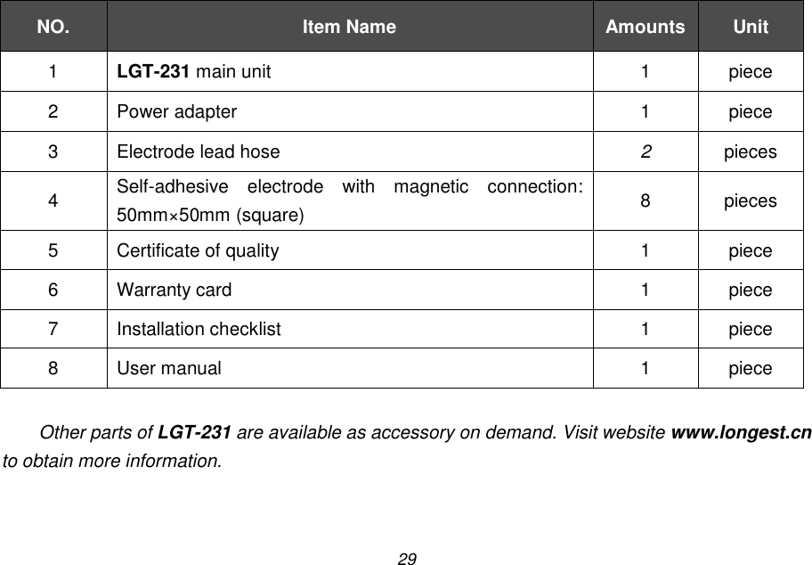
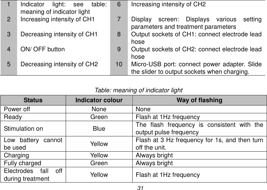
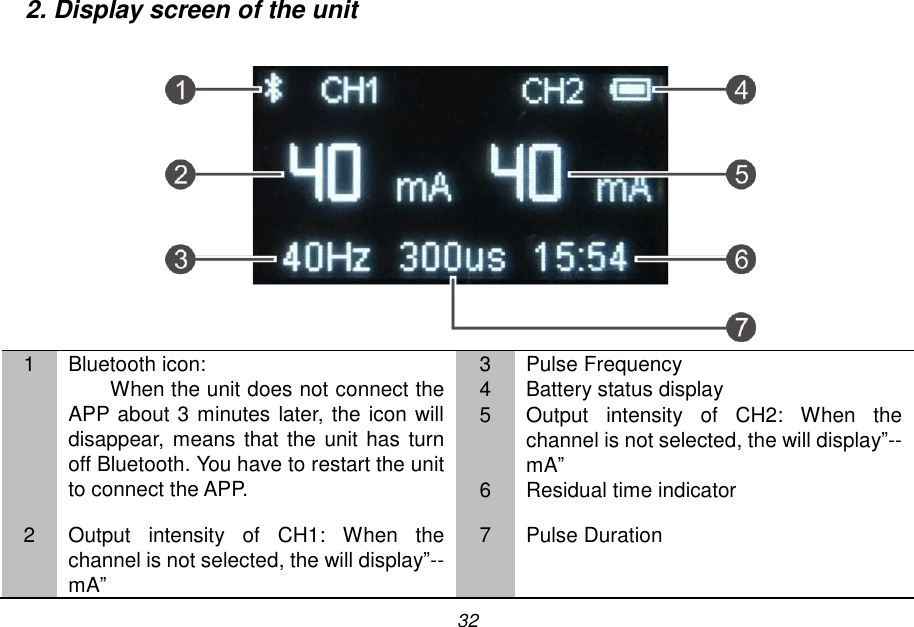
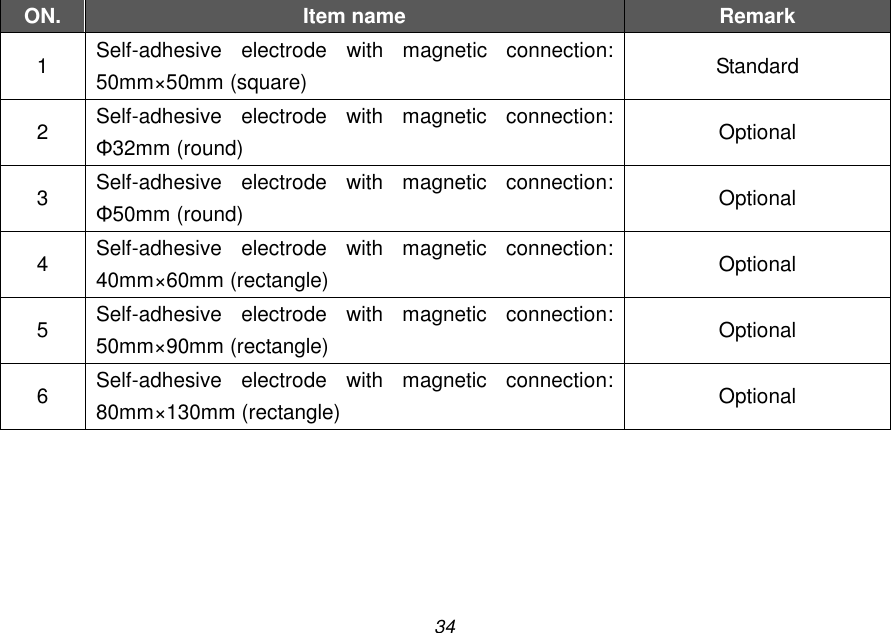
Guangzhou Longest Science and Technology LGT-231 Portable Electro-Stimulation Therapy Device User Manual

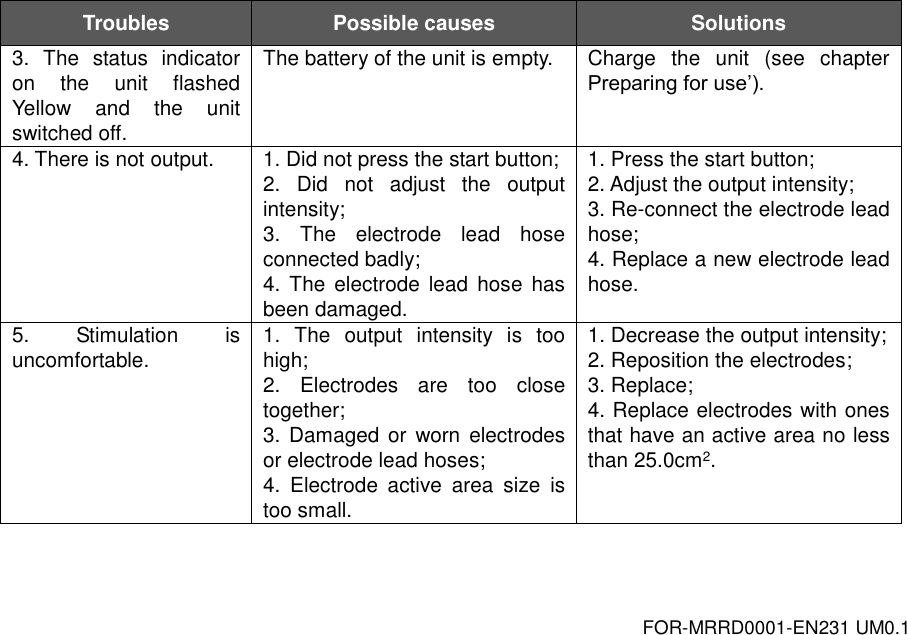
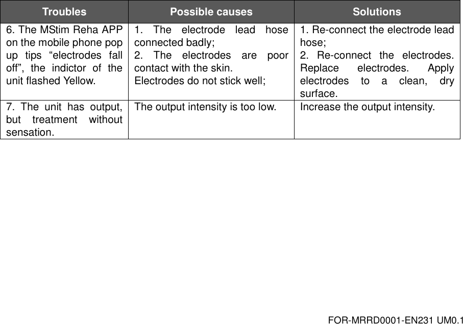
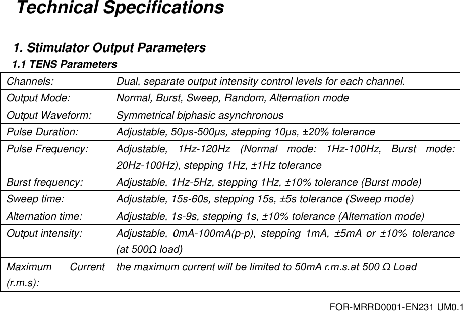
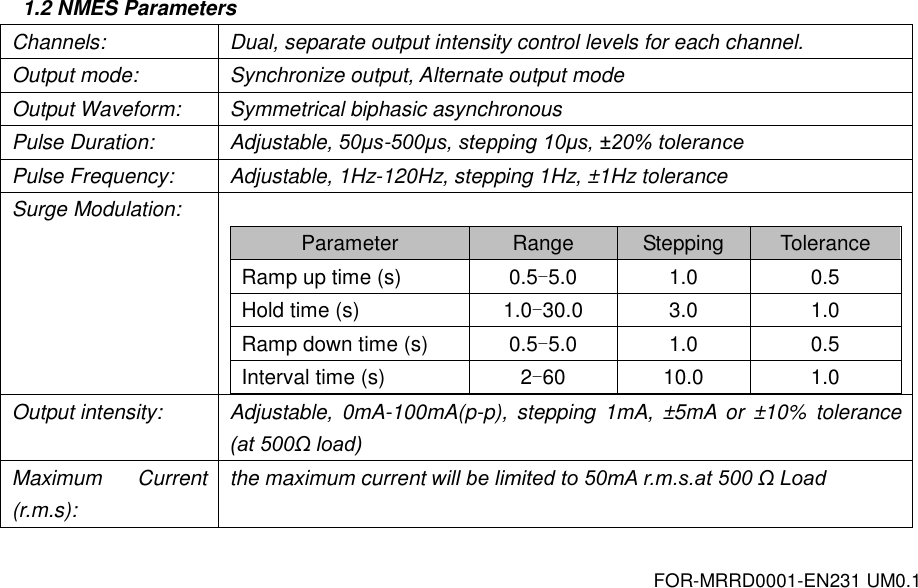
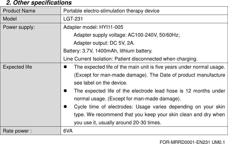
Guangzhou Longest Science & Technology Co., Ltd. Portable Electro-Stimulation Therapy Device Users Manual

Users Manual

  Portable Electro-Stimulation   Therapy Device  USER MANUAL LGT-231    Guangzhou Longest Science & Technology Co., Ltd.
3 TABLE OF CONTENTS Foreword ............................................................................................................................................ 4 Safety Instructions ............................................................................................................................. 6 EMC Guidance................................................................................................................................. 17 Clinical Instructions .......................................................................................................................... 25 Working Principle ............................................................................................................................. 27 Inspection of the Goods ................................................................................................................... 28 Overview of the Unit ........................................................................................................................ 30 MStim Reha Application ................................................................................................................... 35 Operation Guidance ......................................................................................................................... 57 Care and Maintenance .................................................................................................................... 60 Troubleshooting ............................................................................................................................... 63 Technical Specifications ................................................................................................................... 66 Assistance and Spare Parts............................................................................................................. 71 Warranty .......................................................................................................................................... 72
4 Foreword  Thank you for purchasing the LGT-231 Portable Electro-Stimulation Therapy Device from our company. This  manual  has  been  written  for  the  owners  and  operators  of  the  LGT-231  Portable Electro-Stimulation  Therapy  Device.  It  contains  general  information  on  the  instructions  for safety, intended use, working principle, operation, maintenance, troubleshooting, and warranty. In order  to  maximize  the  use,  efficiency,  and  working  life  of  your  unit,  please  read  this  manual thoroughly and become familiar with the controls, as well as the accessories, before operating the unit. Specifications put fifth in this manual were in effect at the time of publication. However, owing to policy of continual improvement by Guangzhou Longest Science & Technology Co., Ltd., any changes  to  these  specifications  may  be  made  at  any  time  without  obligation  on  the  part  of Guangzhou Longest Science & Technology Co., Ltd. Before  administering  any  treatment  to  a  patient,  the  user  of  this  equipment  should  read, understand,  and  follow  the  information  contained  in  this  manual  for  each  mode  of  treatment available, as well as the indications, contraindications, warnings, and precautions.
5  Product Description  The LGT-231 Portable Electro-Stimulation Therapy Device is a lightweight and portable multifunctional electrotherapy device that provides two channels of TENS, NMES current, or one channel of MCR current. It utilizes the low electric-current to stimulate muscle nerve to stimulate nerve and muscle tissue, relieve pain and promote blood circulation, help improve symptoms, relieve pain, restore and strengthen neuromuscular function.
6 Safety Instructions  Symbols 1. Symbols on the medical device Symbols Explanation  Manufacturer  Date of manufacture  EU Representative  This  product  complies  with  European  Directive  93/42  EEC  for  medical products. (0598 is the notified body number)  Correct  Disposal  of This  Product  (Waste  Electrical  &  Electronic  Equipment) Statement:  Contact  the  local  authorities  to  determine  the  proper  method  of disposal of potentially bio-hazardous parts and accessories.
7  Type BF applied part (i.e. electrode) complying with IEC60601-1.  Protected  against  solid  foreign  objects  of  12.5  mm  (0.5  in)  diameter  and greater; Protected  against  vertically  falling  water  drops  when  enclosure  tilted  up  to 15°.    This device emits non-ionizing radiation.  Refer to instruction manual/ booklet  Caution output. It is placed near all electrode connections.  2. Symbols on the package Symbols Explanation  This side up The transportation package must be vertical and straight up during transportation.
8  Fragile, handle with care The product inside the packaging could be easily damaged if dropped or handled without care and attention.  Keep away from rain The  product  package  should keep out  of  the  rain and not to  store  it  in  damp conditions.  Temperature limitation The  product  package  should  be  stored  at  a  temperature between  -20  and  55 degrees (centigrade).  Upper limit of humidity The product package should be stored at a humidity less than 93%.  Atmospheric pressure limitation The  product  package  should  be  stored  at  an  atmospheric  pressure  between 86kPa and 106kPa.
9 Precautionary Definitions  The precautionary instructions found in this section and throughout this manual are indicated by specific symbols. Understand these symbols and their definitions before operating this equipment. The definition of these symbols is as follows:   Text  with  a  “CAUTION”  indicator  will  explain  possible  safety  infractions  that  could  have  the potential to cause minor to moderate injury or damage to equipment.   Text  with  a  “WARNING”  indicator  will  explain  possible  safety  infractions  that  will potentially cause serious injury and equipment damage.   Text  with  a  “DANGER”  indicator  will  explain  possible  safety  infractions  that  are  imminently
10 hazardous situations that would result in death or serious injury.  Explosion Hazard Text  with  an  “Explosion  Hazard”  indicator  will  explain  possible  safety  infractions  if  this equipment is used in the presence of flammable anesthetics.   Dangerous Voltage Text  with  a  ”Dangerous  Voltage”  indicator  serves  to  inform  the  user  of  possible  hazards resulting  in  the  electrical  charge  delivered  to  the  patient  or  operator  in  certain  treatment configurations.    Refer to Instruction Manual/Booklet  NOTE: Throughout this manual, “NOTE” may be found. These Notes are helpful information to aid in the particular area or function being described.
11 Warnings and cautions  Please carefully read and understand the following warnings and cautions to ensure the safe and correct use of the LGT-231 and to prevent injury.   Read, understand, and practice the precautionary operating instructions. Know the limitations and hazards associated with using the LGT-231. Observe the precautionary and operational decals placed on the unit.  Before using LGT-231 make sure you have read and understood all information provided in this manual. Familiarity with the information included in this manual is an essential requirement to ensure efficient  and optimal  use  of the system, to  avoid  dangers  to  persons  and  to  the equipment, and to obtain good treatment results.  Improper installation, operation, or maintenance of the LGT-231 may result in malfunctions of this unit or other devices.  In case of display failure or other obvious defects, switch the unit off immediately, and notify a certified service technician.  Adjustments or replacement of components may result in the equipment failing to meet the requirements for interference suppression.
12  This LGT-231 should be kept out of the reach of children.  Do not use this unit near the heart or chest, above the neck, on the head, around the mouth or on diseased skin;  The placement of the electrodes can be referenced to the reference icon provided by APP, Note that the following parts cannot be placed: a) carotid  sinus  (current  may  affect  blood  pressure  and  cardiac  contraction,  causing arrhythmia); b) infection site (which may aggravate the infection); c)  pregnant women's abdomen and lumbosacral (may cause uterine contractions); d) surgical site (muscle contraction may cause wound dehiscence); e) malignant neoplasms; f) sensory defects or parts that are allergic to the electrodes; g) eye.  Do not use this unit for purposes other than treatment indicated in this manual.  Do not use the LGT-231 with high frequency surgical equipments on the patient. It will cause unstable output when the unit is close to the high frequency equipments (in the same room and without shield).  Do not use this device simultaneously with other therapeutic device (such as microwave), to avoid mis-operation.
13  Do not use electrodes with an active area of less than 25 cm² (when you choose the TENS or NMES mode) due to the risk of associated burning. Proceed systematically with caution when the density of the current is over 2 mA/ cm².  Do not modify this device without authorization of the manufacturer.  Only use this device with the charger, cables, electrodes and accessories recommended by the manufacturer.  The LGT-231 contains built-in batteries that cannot be removed by the user. Do not replace it by yourself to avoid damage the batteries or device. If necessary, please contact the company or the company authorized maintenance personnel to replace.  Please dispose of the equipment and other accessories according to local regulations. Do not treat them as household waste. Do not put the device in fire or water. If the batteries are not properly disposed, it may cause a battery explosion.  Do not use when the unit is charging.   Always check the device and the electrodes for damage before use.  If the unit is not functioning properly or you feel discomfort, immediately stop using the unit. If you feel any trouble with your body or skin, consult the doctor and follow his/her instructions.  The self-adhesive electrode limited to the same person to use, do not use in another patients
14 to prevent infection.  If the electrode loses viscosity, please replace the electrode in order to maintain good electrical properties.  Do not use this unit in places with high humidity such as the bathrooms or while taking a bath or shower.  Do not use this unit while sleeping. The main unit may develop trouble, or the pad may move to an unexpected region and cause ill health.  Clean  the  device  using  a  dry  soft  cloth.  Do  not  use  cleaning  solvents  or  other  chemical substances in order to avoid any damage.  Make sure that you end the treatment by switching off the units or by setting the intensity to 0 mA before you remove the units or the electrodes. If you do not end the treatment, you may experience an unpleasant sensation in your fingers. This sensation is not harmful, but can be unpleasant.  Handle the unit with care. Do not drop, knock, or shake the unit. Rough handling can damage internal circuit boards.  Do  not  apply  stimulation  while driving, operating machines or while performing any other activity in which electrical stimulation can put you at risk of injury.  Always disconnect the power charger from the mains after use.
15 FCC  Changes or modifications not expressly approved by the party responsible for compliance could void the user’s authority to operate the equipment. This equipment has  been  tested and found  to comply with the  limits for  a Class B digital device, pursuant to Part 15 of the FCC Rules. These limits are designed to provide reasonable protection  against  harmful  interference  in  a  residential  installation.  This  equipment  generates, uses and can radiate radio frequency energy and, if not installed and used in accordance with the instructions,  may  cause  harmful  interference  to  radio  communications.  However,  there  is  no guarantee that interference will not occur in a particular installation. If this equipment does cause harmful interference to radio or television reception, which can be determined by turning the equipment off and on, the user is encouraged to try to correct the interference by one or more of the following measures: -- Reorient or relocate the receiving antenna. -- Increase the separation between the equipment and receiver. -- Connect the equipment into an outlet on a circuit different from that to which the receiver is connected. -- Consult the dealer or an experienced radio/TV technician for help.
16 This device complies with Part 15 of the FCC Rules. Operation is subject to the following two conditions: (1) this device may not cause harmful interference, and (2) this device must accept any interference received, including interference that may cause undesired operation. FCC RF warning statement:  The device has been evaluated to meet general RF exposure requirement. The device can be used in portable exposure condition without restriction. This device and its antenna(s) must not be co-located or operation in conjunction with any other antenna or transmitter.  FCC ID: 2ANHPLGT-231
17 EMC Guidance  This product needs special precautions regarding EMC and needs to be installed and put into service according to the EMC information provided, and this unit can be affected by portable and mobile RF communications equipment.    Do not use a mobile phone or other devices that emit electromagnetic fields, near the unit. This may result in incorrect operation of the unit.  This  unit  has  been  thoroughly  tested  and  inspected  to  assure  proper  performance  and operation!  This machine should not be used adjacent to or stacked with other equipment  and that if adjacent  or  stacked  use  is  necessary,  this  machine  should  be  observed  to  verify  normal operation in the configuration in which it will be used.
18  Accessory Information:   Item Cable Length Manufacturer & Address Power cord (adapter) 0.96 m Shenzhen Hongyi Electronic Technology Co., Ltd. A05-1, 2/F, 3 Bldg, EC building, Yu Anju, Baoan District, Shenzhen, China Electrode lead hose 1.2 m Guangzhou Longest Science & Technology Co., Ltd. 5&6F, Building B4, No.11, Kaiyuan Avenue, Science City, Guangzhou Hi-tech Industrial  Development  Zone,  510530  Guangzhou,  Guangdong  Province, P.R. China   Bluetooth Specifications: Bluetooth version: 4.0 single mode Frequency Range: 2.402GHz ~ 2.480GHz Output Power: 1mW
19  Guidance and manufacture’s declaration – electromagnetic emission The LGT-231 is intended for use in the electromagnetic environment specified below. The customer of the user of the LGT-231 should assure that it is used in such an environment. Emission test Compliance Electromagnetic environment – guidance RF emissions CISPR 11 Group 1 The  LGT-231 use  RF energy only for  its internal function. Therefore, its RF emissions are very low and  are  not  likely  to  cause  any  interference  in nearby electronic equipment. RF emission CISPR 11 Class B The  LGT-231  is  suitable  for  use  in  all establishments,  including  domestic establishments and those directly connected to the public  low-voltage  pump  supply  network  that supplies buildings used for domestic purposes. Harmonic emissions IEC 61000-3-2 Class A Voltage  fluctuations/ flicker emissions IEC 61000-3-3 Complies
20  Guidance and manufacture’s declaration – electromagnetic immunity The LGT-231 is intended for use in the electromagnetic environment specified below. The customer or the user of LGT-231 should assure that it is used in such an environment. Immunity test IEC 60601 test level Compliance level Electromagnetic environment - guidance Electrostatic discharge (ESD) IEC 61000-4-2 ±6 kV contact ±8 kV air ±6 kV contact ±8 kV air Floors should be wood, concrete or  ceramic  tile.  If  floor  are covered  with  synthetic  material, the relative humidity should be at least 30%. Electrical fast transient/ burst IEC 61000-4-4 ±2 kV for power supply lines ±1 kV for input/output    lines ±2kV for power supply lines Mains  power  quality  should  be that  of  a  typical  commercial  or hospital environment. Surge IEC 61000-4-5 ± 1 kV line(s) to line(s) ±  2 kV line(s) to earth ±1 kV differential mode Mains  power  quality  should  be that  of  a  typical  commercial  or hospital environment. Voltage dips, short interruptions and voltage <5% UT (>95% dip in UT) for 0.5 cycle 40% UT (60% dip in <5% UT (>95% dip in UT) for 0.5 cycle 40% UT (60% dip in Mains  power  quality  should  be that  of  a  typical  commercial  or hospital environment. If the user of  the  LGT-231  requires
21 variations on power supply input lines IEC 61000-4-11 UT) for 5 cycles 70% UT (30% dip in UT) for 25 cycles <5% UT    (>95% dip in UT) for 5 sec UT) for 5 cycles 70% UT (30% dip in UT) for 25 cycles <5% UT (>95% dip in UT) for 5 sec continued  operation  during power  mains  interruptions,  it  is recommended that the LGT-231 be  powered  from  an uninterruptible power supply or a battery. Power frequency (50Hz/60Hz) magnetic  field IEC 61000-4-8 3 A/m 3 A/m Power frequency magnetic fields should be at levels characteristic of  a  typical  location  in  a  typical commercial  or  hospital environment. NOTE    UT is the a.c. mains voltage prior to application of the test level.
22  Guidance and manufacture’s declaration – electromagnetic immunity The LGT-231 is intended for use in the electromagnetic environment specified below. The customer or the user of the LGT-231 should assure that it is used in such an environment. Immunity test IEC  60601 test level Compliance level Electromagnetic environment - guidance       Conducted RF IEC 61000-4-6   Radiated RF IEC 61000-4-3       3 Vrms 150 kHz to 80 MHz  3 V/m 80 MHz to 2.5 GHz       3 Vrms    3 V/m Portable  and  mobile  RF  communications equipment should be used no closer to any part of the  LGT-231,  including  cables,  than  the recommended separation distance calculated from the  equation  applicable  to  the  frequency  of  the transmitter. Recommended separation distance d = 1.2 √P    d = 1.2 √P     80 MHz to 800 MHz   d = 2.3 √P      800 MHz to 2.5 GHz  Where P is  the maximum output power rating  of
23 the  transmitter  in  watts  (W)  according  to  the transmitter  manufacturer  and  d  is  the recommended separation distance in metres (m). Field  strengths  from  fixed  RF  transmitters,  as determined  by  an  electromagnetic  site  survey,a should be less than the compliance level in each frequency range.b Interference may occur in the vicinity of equipment marked with the following symbol:  NOTE 1    At 80 MHz and 800 MHz, the higher frequency range applies. NOTE  2    These  guidelines may not apply  in  all  situations.  Electromagnetic propagation  is affected by absorption and reflection from structures, objects and people. a    Field strengths from fixed transmitters, such as base stations for radio (cellular/cordless) telephones  and  land  mobile  radios,  amateur  radio,  AM  and  FM  radio  broadcast  and  TV broadcast cannot be predicted theoretically with accuracy. To assess the electromagnetic environment  due  to  fixed  RF  transmitters,  an  electromagnetic  site  survey  should  be considered.  If  the  measured  field  strength  in  the  location  in  which  the  LGT-231  is  used exceeds  the  applicable  RF compliance level above, the  LGT-231  should  be  observed to verify normal operation. If abnormal performance is observed, additional measures may be necessary, such as re-orienting or relocating the LGT-31. b    Over the frequency range 150 kHz to 80 MHz, field strengths should be less than 3 V/m.
24  Recommended separation distances between portable and mobile RF communications equipment and the LGT-231 The  LGT-231 is  intended for use in an electromagnetic environment in which radiated RF disturbances  are  controlled.  The  customer  or  the  user  of  the  LGT-231  can  help  prevent electromagnetic interference by maintaining a minimum distance between portable and mobile RF communications equipment (transmitters) and the LGT-231 as recommended below, according to the maximum output power of the communications equipment. Rated  maximum output  power  of transmitter (W) Separation distance according to frequency of transmitter (m) 150 KHz to 80 MHz d = 1.2 √P 80 MHz to 800 MHz d = 1.2 √P 800 MHz to 2.5 GHz d = 2.3 √P 0.01 0.12 0.12 0.23 0.1 0.38 0.38 0.73 1 1.2 1.2 2.3 10 3.8 3.8 7.3 100 12 12 23 For transmitters rated at a maximum output power not listed above, the recommended separation distance d in metres (m) can be estimated using the equation applicable to the frequency of the transmitter, where P is the maximum output power rating of the transmitter in watts (W) according to the transmitter manufacturer. NOTE 1    At 80MHz and 800MHz, the separation distance for the higher frequency range applies. NOTE 2    These guidelines may not apply in all situations. Electromagnetic propagation is affected by absorption and reflection from structures, objects and people.
25 Clinical Instructions  Before  a  treatment  with  the  LGT-231  Portable  Electro-Stimulation  Therapy  Device,  a correct examination and diagnosis should be performed.  Indications The  LGT-231  Portable  Electro-Stimulation  Therapy  Device  can  alleviate  acute  and chronic pain, also can stimulate nerves and muscles, causing muscle contraction.  Contraindications Patients  with  the  following  disease  are  forbidden  to  use  the  LGT-231  Portable Electro-Stimulation Therapy Device: 1)  Patient with severe heart failure or arrhythmia, and patient with pacemaker; 2)  Patient with venous thrombosis or thrombophlebitis; 3)  Patient who is in the acute or critical stage of important organ disease; 4)  Patient whose treatment area with bleeding tendency,metal matter or tuberculous lesions; 5)  Patients who cannot  provide sensory feedback for stimulation (unable to express or have difficulty in communication),such as mental disease.
26 Adverse Effects You should stop using the device and consult your doctor if you experience adverse reactions from the device. Possible adverse reactions may include the following:  skin irritation beneath the electrodes;  burns beneath the electrodes;  headaches or other painful sensations.
27 Working Principle AC InputProcessorPWM Intensity AdjustmentPulse Generating ElectrodeCurrent FeedbackDisplay ScreenCommunication of Mobile Phone APP and BluetoothBluetooth ChipBatteryPower AdapterButton
28 Inspection of the Goods  1. Unpacking the Unit The  unit  is  generally  delivered  with  the  packaging  material  supplied  by  the  manufacturer. Proceed as follows:  Position the transport packaging so that the arrows are pointing upward.  Remove the transport packaging upward.  Remove the remaining foam material.  2. Inspections Immediately upon unpacking the unit, perform the following steps: 1) Verify the delivery documents to make sure that the delivery is complete. 2) Check the LCD touch screen of the unit when unpack the packaging and make sure it is in good condition. Any scratch on the surface during use will be not covered in the warranty. 3) Check the external components and accessories for possible damage due to transport. 4) Verify that the packaging contains the following:
29 NO. Item Name Amounts Unit 1 LGT-231 main unit 1 piece 2 Power adapter 1 piece 3 Electrode lead hose 2 pieces 4 Self-adhesive  electrode  with  magnetic  connection: 50mm×50mm (square) 8 pieces 5 Certificate of quality 1 piece 6 Warranty card 1 piece 7 Installation checklist 1 piece 8 User manual 1 piece  Other parts of LGT-231 are available as accessory on demand. Visit website www.longest.cn to obtain more information.
30 Overview of the Unit  1. Nomenclature
31 1 Indicator  light:  see  table: meaning of indicator light 6 Increasing intensity of CH2 2 Increasing intensity of CH1 7 Display  screen:  Displays  various  setting parameters and treatment parameters 3 Decreasing intensity of CH1 8 Output sockets of CH1: connect electrode lead hose 4 ON/ OFF button 9 Output sockets of CH2: connect electrode lead hose 5 Decreasing intensity of CH2 10 Micro-USB port: connect  power adapter. Slide the slider to output sockets when charging.  Table: meaning of indicator light Status Indicator colour Way of flashing Power off None None Ready Green Flash at 1Hz frequency Stimulation on Blue The  flash  frequency  is  consistent  with  the output pulse frequency Low  battery  cannot be used Yellow Flash at 3 Hz frequency for 1s, and then turn off the unit. Charging Yellow Always bright Fully charged Green Always bright Electrodes  fall  off during treatment Yellow Flash at 1Hz frequency
32 2. Display screen of the unit   1 Bluetooth icon:   When the unit does not connect the APP about 3 minutes later, the icon will disappear, means that the unit has  turn off Bluetooth. You have to restart the unit to connect the APP. 3 Pulse Frequency 4 Battery status display 5 Output  intensity  of  CH2:  When  the channel is not selected, the will display”-- mA” 6 Residual time indicator 2 Output  intensity  of  CH1:  When  the channel is not selected, the will display”-- mA” 7 Pulse Duration
33 3. Accessories 3.1 Electrode lead hose  The electrode lead hose connect with the main unit and electrodes.  3.2 Self-adhesive electrode with magnetic connection
34 ON. Item name Remark 1 Self-adhesive  electrode  with  magnetic  connection: 50mm×50mm (square) Standard 2 Self-adhesive  electrode  with  magnetic  connection: Φ32mm (round) Optional 3 Self-adhesive  electrode  with  magnetic  connection: Φ50mm (round) Optional 4 Self-adhesive  electrode  with  magnetic  connection: 40mm×60mm (rectangle) Optional 5 Self-adhesive  electrode  with  magnetic  connection: 50mm×90mm (rectangle) Optional 6 Self-adhesive  electrode  with  magnetic  connection: 80mm×130mm (rectangle) Optional
35 MStim Reha Application  LGT-231  Portable Electro-Stimulation  Therapy Device can only be used with the software provided by our company.   Name of the software: MStim Reha  Release Version: 1  Software operating environment:   Android 4.3 or later mobile phone, with 4.0 Bluetooth. iOS 8 or later iPhone mobile phone, with 4.0 Bluetooth.
36  1. Install MStim Reha Application Click  the  MStim  Reha  Application  installation package  (APK  file)  on  your  phone,  and  follow  the prompts to install the application.  2. Open MStim Reha Application After  the  MStim  Reha  Application  is  installed properly,  it  will  appear    on  your  phone  desktop. Click the icon and the main interface of the MStim Reha appear, as shown on the left.
37 3. Connect the Device Click “connect the device” to connect MStim Reha Application which on the phone and the device via Bluetooth.
38    4. Main Interface Open MStim Reha, you can see the main interface, as shown on the left. There are three modes on the MStim Reha: TENS Mode, NMES Mode and MCR Mode.
39   4.1 TENS Interface 1)  Enter TENS interface Click TENS at the main interface to enter the TENS interface, as shown on the left. 2)  Select output channel Select single or dual channel outputs as needed. 3)  Choose output mode TENS  has  four  output  modes:  Normal,  Sweep, Random  and  Alternation  mode. The Alternate mode  is only  used  for  dual  channel  output.  The  parameters  of each mode are shown in Table: TENS parameter setting.
40 Table: TENS parameter setting Output Mode: Normal Output Mode: Sweep parameter setting Range Default Stepping parameter setting Range Default Stepping Frequency Hz 1-100 40 1 Frequency Hz 1-100 40 1 Pulse Duration μs 50-500 300 10 Pulse Duration μs 50-500 300 10 Burst Frequency Hz 1-5 1 1 Sweep time s 15-60 30 15 Treatment time min 1-60 10 1 Treatment time min 1-60 10 1 Output intensity mA 0-100 0 1 Output intensity mA 0-100 0 1 Output Mode: Random Output Mode: Alternation parameter setting Range Default Stepping parameter setting Range Default Stepping Frequency Hz 1-100 40 1 Frequency Hz 1-100 40 1 Pulse Duration μs 50-500 300 10 Pulse Duration μs 50-500 300 10 Treatment time min 1-60 10 1 Alternation time s 1-9 4 1 Output intensity mA 0-100 0 1 Treatment time min 1-60 10 1     Output intensity mA 0-100 0 1 NOTE: The output intensity can only be adjusted after starting.
41   4) Start treatment When the parameter is set, click the start button to start the treatment. 5) Adjust output intensity Click  the  start  button,  the  output  intensity  can  be adjusted. Click    button, interface pop-up tip:
42    6)  locking interface The  APP  locks  automatically  after  some  time  of inactivity to prevent accidental operation. Just press the avatar swipe screen to unlock. 7) End of the treatment At  the  end  of  the  treatment,  the  unit  stops  output and  returns  to  the  pre  start  state.  The  indicator  is switched  from  blue  to  green  and  flashes  at  1Hz frequency, while the mobile application interface shows "the treatment is finish."
43    4.2 NMES Interface 1) Enter NMES Interface Click NMES at the main interface to enter the NMES interface, as shown on the left. 2) Select output channel Select single or dual channel outputs as needed. 3) Choose output mode NMES  has  two  output  modes:  Synchronize output and Alternate output mode. The Alternate mode is only used for dual channel  output. The  parameters  of  each mode are shown in Table: NMES parameter setting.  NOTE: You can choose output mode only select the dual channel outputs.
44   4) NMES parameter setting Table: NMES parameter setting parameter setting Range Default Stepping Frequency Hz 1-120 40 1 Pulse Duration μs 50-500 300 10 Surge Modulation*-1    Ramp up time s 0.5-5.0 1.0 0.5 Hold time s 1.0-30.0 3.0 1.0 Ramp down time s 0.5-5.0 1.0 0.5 Interval time s 5-60 10.0 1.0 Treatment time min 1-60 10 1 Output Intensiyt mA*-2 0-100 0 1 *-1 The Surge  Modulation Interface is as shown on the left. *-2  The  output  intensity  can  only  be  adjusted  after starting.
45   5) Start treatment When the parameter is set, click the start button to start the treatment. 6) Adjust output intensity Click  the  start  button,  the  output  intensity  can  be adjusted. Click    button, interface pop-up tip:
46   7) End of the treatment At  the  end  of  the  treatment,  the  unit  stops  output and  returns  to  the  pre  start  state.  The  indicator  is switched  from  blue  to  green  and  flashes  at  1Hz frequency, while the mobile application interface shows "the treatment is finish."
47    4.3 MCR Interface Click MCR at the main interface to enter the MCR interface, as shown on the left. Table: MCR parameter setting parameter setting Range Default Stepping Frequency Hz 1-100 50 1 Treatment time min 1-60 10 1 Output intensity μA 0-1000 0 10  NOTE: The output intensity can only be  adjusted  after starting.
48    5. Open circuit tip When the treatment electrode is disconnected, the device  appears  with  the  following  prompt,  please re-paste the electrode.
49    6. Help Click the icon    in the upper right corner of the main interface, or slide the interface in the main interface to  see  more,  click  the  icon  ,  enter  the  help interface.
50    6.1 Using guidance There is some introduction of how to operation the LGT-231  Portable  Electro-Stimulation  Therapy Device in using guidance, which is convenient for you to understand the use of device.
51  6.2 Common problem MStim  Reha  Application  includes  a  variety  of common  problems,  you  can  learn  more  about  the LGT-231  Portable  Electro-Stimulation  Therapy Device and treatment.
52 7. Preset protocols 7.1 Add protocols MStim  Reha  Application  internally  installed  21  preset  protocols.  You  can  click  “Preset protocols” to enter the interface. You can click “Add more protocols”, choose the protocols you need, and then click OK button, the operation as following pictures.
53    7.2 Delete or sort the protocols To delete a protocol, click the "Edit" button and click " " to delete it. To sort the protocols, press and hold " "  to  drag  the  prescription.  Click  "Finish"  when finished.
FOR-MRRD0001-EN231 UM0.1 7.3 Treatment from the preset protocols Choose  the  right  protocol  for  treatment  as  needed.  For  example,  select  "Cerebral  stroke  - NMES", as shown in the following figure.
FOR-MRRD0001-EN231 UM0.1 Please click the color area to select the treatment parts, and then click OK button to enter the treatment  parameters  interface.  You  can  modify  the  parameters  as  need,  and  then  click  “start treatment”.
FOR-MRRD0001-EN231 UM0.1 Operation Guidance  1. Preparing for use  1.1 Charging the unit To be able to use the device, you first have to charge the unit. Put one side of power adapter connects with the unit; another side connects with the power socket. The status indicator on the unit flashes yellow during charging. The status indicator stops flashing turn to green when the battery is fully charged.  NOTE: If the rechargeable battery of the units is not fully charged when you start a treatment, the batteries may run out during the treatment. We advise you to always fully charge the unit before you start a treatment. NOTE: Always disconnect the power charger from the mains after use.   Do not use when the unit is charging.
FOR-MRRD0001-EN231 UM0.1  1.2 Turn on the unit Press the ON/OFF button to turn on the unit to standby. 1.3 Open the MStim Reha and connecting Turn on the MStim Reha Application on your phone and connect the unit to your phone via Bluetooth. 1.4 Clean the skin Use alcohol or soapy water to clean the skin. 1.5 Place the electrodes Place electrodes according to reference or actual conditions. 1.6 Connect the unit Connect one end of electrode lead hose to the electrodes, the other end to the unit.  2. Starting a Treatment 2.1 Parameter Setting According  to  the  actual  situation,  choose  the  appropriate  electrical  stimulation  therapy  or protocol,  set  the  treatment  parameters,  treatment  time,  etc.  (see  the  chapter  MStim  Reha Application) 2.2 Press the START button
FOR-MRRD0001-EN231 UM0.1 Click the start button and the treatment begins. 2.3 Adjust output intensity You can adjust the output intensity in the MStim Reha interface, or through "+/-" button on the unit.  The  output  intensity  should  be  increased  slowly  from  small  values  to  avoid  excessive stimulation.  Since your body  initially adapts to the intensity of the stimulation, you  may have to adjust the intensity level after some time to ensure optimal stimulation. 2.4 The End of Treatment At  the  end  of  the  treatment,  the  unit  stops  output  and  returns  to  the  pre  start  state.  The indicator is switched from blue to green and flashes at 1Hz frequency, while the mobile application interface shows "the treatment is finish." Remove the electrodes after treatment, paste it back to the plastic film and store the unit well.
FOR-MRRD0001-EN231 UM0.1 Care and Maintenance  1. Cleaning 1)  Please turn off the device before the cleaning and disinfection operation; 2)  For the main unit cleaning, what recommended are a clean, soft damp cloth for stains, and a clean, soft dry cloth for dust in the surface of the main unit.   Do not clean the main unit with organic solvent such as gasoline or diluents, otherwise damage will be happened to the main unit such as deformation and falling off of the paint.  2. Routine Maintenance If it is used in accordance with the instructions of the user manual, the device does not need a particular regular maintenance. Manufacturer  will  provide  circuit  diagrams,  component  part  lists,  descriptions,  calibration instructions to assist to service personnel in parts repair. The unit and accessories must be checked at regular intervals.
FOR-MRRD0001-EN231 UM0.1 1)  Check the power line to ensure if there is no distortion, fracture, etc. These circumstances may cause fire hazard. Please replace a new power line immediately. 2) Replace the electrodes if: -- they are damaged or torn. -- they are past the use-by date. -- they have lost their adhesive power. Never use plaster or tape to attach them to your skin. -- stimulation feels less strong. -- when the stimulation is uncomfortable, i.e. when you experience an unpleasant stinging or biting sensation. NOTE:  Always  replace  the  electrodes  with  electrodes  recommended  for  this  device  by  the manufacturer.   Never perform unauthorized service work. All service work must be performed only by service technicians who have been authorized by the manufacturer.
FOR-MRRD0001-EN231 UM0.1 3. DISPOSAL  For environmental reasons, do not dispose of the device in the household waste at the end of its useful life. Dispose of the unit at a suitable local collection or recycling point. Dispose of the device in accordance with EC Directive – WEEE (Waste Electrical and Electronic Equipment). If you have any questions, please contact the local authorities responsible for waste disposal.
FOR-MRRD0001-EN231 UM0.1 Troubleshooting  This chapter summarizes the most common problems you could encounter with the LGT-231 Portable  Electro-Stimulation  Therapy  Device.  If  you  are  unable  to  solve  the  problem  with  the information below, please call the distributors. Troubles Possible causes Solutions 1. LCD Display does not light up at all when press the ON/OFF button The battery of the unit is empty. Charge  the  unit  (see  chapter Preparing for use’). 2. The MStim Reha APP on  the  mobile  phone could  not  connect  with the unit. 1. The unit is not turn on; 2. Mobile phone Bluetooth is not open or mobile phone Bluetooth problems 3.  the  distance  of  the  mobile phone and the unit is too far; 4.  The  unit  has  contacted another mobile. The unit is asleep and Bluetooth is stopped. 1. Turn on the unit; 2. Please turn  on  the  Bluetooth on the  mobile  phone or  change another mobile phone; 3. Please keep the mobile phone near the unit; 4.  Disconnect  the  connected phone or restart the unit; 5. Restart the unit.
FOR-MRRD0001-EN231 UM0.1 Troubles Possible causes Solutions 3.  The  status  indicator on  the  unit  flashed Yellow  and  the  unit switched off. The battery of the unit is empty. Charge  the  unit  (see  chapter Preparing for use’). 4. There is not output. 1. Did not press the start button; 2.  Did  not  adjust  the  output intensity; 3.  The  electrode  lead  hose connected badly; 4.  The  electrode  lead  hose  has been damaged. 1. Press the start button; 2. Adjust the output intensity; 3. Re-connect the electrode lead hose; 4. Replace a new electrode lead hose. 5.  Stimulation  is uncomfortable. 1.  The  output  intensity  is  too high; 2.  Electrodes  are  too  close together; 3. Damaged or  worn electrodes or electrode lead hoses; 4.  Electrode  active  area  size  is too small. 1. Decrease the output intensity; 2. Reposition the electrodes; 3. Replace; 4. Replace electrodes with ones that have an active area no less than 25.0cm2.
FOR-MRRD0001-EN231 UM0.1 Troubles Possible causes Solutions 6. The MStim Reha APP on the mobile phone pop up  tips  “electrodes  fall off”,  the  indictor  of  the unit flashed Yellow. 1.  The  electrode  lead  hose connected badly; 2.  The  electrodes  are  poor contact with the skin. Electrodes do not stick well; 1. Re-connect the electrode lead hose; 2.  Re-connect  the  electrodes. Replace  electrodes.  Apply electrodes  to  a  clean,  dry surface. 7.  The  unit  has  output, but  treatment  without sensation. The output intensity is too low. Increase the output intensity.
FOR-MRRD0001-EN231 UM0.1 Technical Specifications  1. Stimulator Output Parameters 1.1 TENS Parameters Channels: Dual, separate output intensity control levels for each channel. Output Mode: Normal, Burst, Sweep, Random, Alternation mode Output Waveform: Symmetrical biphasic asynchronous Pulse Duration: Adjustable, 50μs-500μs, stepping 10μs, ±20% tolerance Pulse Frequency: Adjustable,  1Hz-120Hz  (Normal  mode:  1Hz-100Hz,  Burst  mode: 20Hz-100Hz), stepping 1Hz, ±1Hz tolerance Burst frequency: Adjustable, 1Hz-5Hz, stepping 1Hz, ±10% tolerance (Burst mode) Sweep time: Adjustable, 15s-60s, stepping 15s, ±5s tolerance (Sweep mode) Alternation time:   Adjustable, 1s-9s, stepping 1s, ±10% tolerance (Alternation mode) Output intensity: Adjustable,  0mA-100mA(p-p),  stepping  1mA, ±5mA  or  ±10%  tolerance (at 500Ω load) Maximum  Current (r.m.s): the maximum current will be limited to 50mA r.m.s.at 500 Ω Load
FOR-MRRD0001-EN231 UM0.1  1.2 NMES Parameters Channels: Dual, separate output intensity control levels for each channel. Output mode: Synchronize output, Alternate output mode Output Waveform: Symmetrical biphasic asynchronous Pulse Duration: Adjustable, 50μs-500μs, stepping 10μs, ±20% tolerance Pulse Frequency: Adjustable, 1Hz-120Hz, stepping 1Hz, ±1Hz tolerance Surge Modulation:  Parameter Range Stepping Tolerance Ramp up time (s) 0.5-5.0 1.0 0.5 Hold time (s) 1.0-30.0 3.0 1.0 Ramp down time (s) 0.5-5.0 1.0 0.5 Interval time (s) 2-60 10.0 1.0  Output intensity: Adjustable,  0mA-100mA(p-p),  stepping  1mA, ±5mA  or  ±10%  tolerance (at 500Ω load) Maximum  Current (r.m.s): the maximum current will be limited to 50mA r.m.s.at 500 Ω Load
FOR-MRRD0001-EN231 UM0.1  1.3 MCR Parameters Channels: One channel Output Waveform: Symmetrical biphasic asynchronous Pulse Frequency: Adjustable, 1Hz-100Hz, stepping 1Hz, ±1Hz tolerance Pulse Duration: 50% of Output Cycle, ±1 0% tolerance Output intensity: Adjustable, 0μA -100μA, stepping 10 μA, ±1 mA or ±10% tolerance, take larger values (at 500Ω load) Maximum  Current (r.m.s): the maximum current will be limited to 5mA r.m.s.at 500 Ω Load  1.4 Timer a) Treatment time: 1min-60min, stepping 1min; b) Timer tolerance: ±2%; c) When finish, the device can stop output and prompt. 1.5 Software Function a)  has 21 preset protocols; b)  has battery level display function.
FOR-MRRD0001-EN231 UM0.1  2. Other specifications Product Name Portable electro-stimulation therapy device Model LGT-231 Power supply: Adapter model: HYI11-005 Adapter supply voltage: AC100-240V, 50/60Hz; Adapter output: DC 5V, 2A. Battery: 3.7V, 1400mAh, lithium battery. Line Current Isolation: Patient disconnected when charging. Expected life   The expected life of the main unit is five years under normal usage. (Except for man-made damage). The Date of product manufacture see label on the device.   The expected life of the electrode lead hose is 12 months under normal usage. (Except for man-made damage).   Cycle  time  of  electrodes:  Usage  varies  depending  on  your  skin type. We recommend that you keep your skin clean and dry when you use it, usually around 20-30 times. Rate power : 6VA
FOR-MRRD0001-EN231 UM0.1 Dimension: 62mm (W) ×  122mm (L) ×  27mm (H) Weight: 120g (only main unit) Classification:   Classification (IEC 60601-1): Class II, Type BF Applied Part;   Ingress Protection: IP22;   Mode of operation: Continuous. Environmental conditions of operation:   Temperature: 5 to 40℃;  Rel. humidity: ≤80%;   Atmosphere Pressure: 86.0 to 106.0kPa. Environmental conditions  of  transport and storage:   Temperature: -20 to 55℃  Rel. humidity: ≤93%   Atmosphere Pressure:86.0 to 106.0kPa Works with: Requires a smart phone with Bluetooth 4.0, Android 4.3 (or later) or iOS 8 or later.
FOR-MRRD0001-EN231 UM0.1 Assistance and Spare Parts  Every  intervention  on  device  must  be  performed  by  manufacturer.  For  any  assistance intervention and original spare parts please contact the manufacturer at following address: GUANGZHOU LONGEST SCIENCE & TECHNOLOGY CO., LTD. Add: 5&6F, Building B4, No.11, Kaiyuan Avenue, Science City, Guangzhou Hi-tech Industrial Development Zone, 510530 Guangzhou, Guangdong Province, P.R. China Tel: +86 20 6635 3999              Fax: +86 20 6635 3920 Email: service@longest.cn                    Website: www.longest.cn EU Representatives Information Lotus Global Co., Ltd Company  address:  1  Four  Seasons  Terrace  West  Drayton,  Middlesex  London,  UB7  9GG, United Kingdom Tel: +44 20 75868010, 70961611        Fax: +44 20 79006187  To  preserve  product  warranty,  functionality  and  product  safety  we  recommend  using  only original spare parts.
FOR-MRRD0001-EN231 UM0.1 Warranty The Manufacturer warrants that the LGT-231 is free of defects in material and workmanship for the main unit. This warranty shall remain in effect for one year (12 months) from the date of original consumer purchase. If this Product fails to function during the one year warranty period due to a defect in material or workmanship, at the Manufacturer's Option, Manufacturer or the authorized dealer will repair this Product without charge.   The users should fill out the Warranty Card as soon as the product is installed and send a copy to service@longest.cn to have the warranty be valid. Damages due to non-adherence to the User Manual or wear of parts are excluded from warranty. This Warranty Does Not Cover:  Replacement parts or labor furnished by anyone other than the Manufacturer, the authorized dealer or a certified Company service technician.  Defects  or  damage  caused  by  labor  furnished  by  someone  other  than  Manufacturer,  the authorized dealer or a certified Company service technician.  Any malfunction or failure in the Product caused by product misuse, including, but not limited to, the failure to provide reasonable and necessary maintenance or any use that is inconsistent with the User Manual.

Navigation menu