HACH LANGE LXG440 Probe for water analysis with rfid interface User Manual DOC023 53 90137
HACH LANGE GmbH Probe for water analysis with rfid interface DOC023 53 90137
UserManual.wiki
>
HACH LANGE
>
LXG440 User Manual
LXG440_UsMan
Navigation menu
Upload a User Manual
Namespaces
Wiki Guide
HTML
PDF
Info
Views
User Manual
Discussion / Help
Navigation
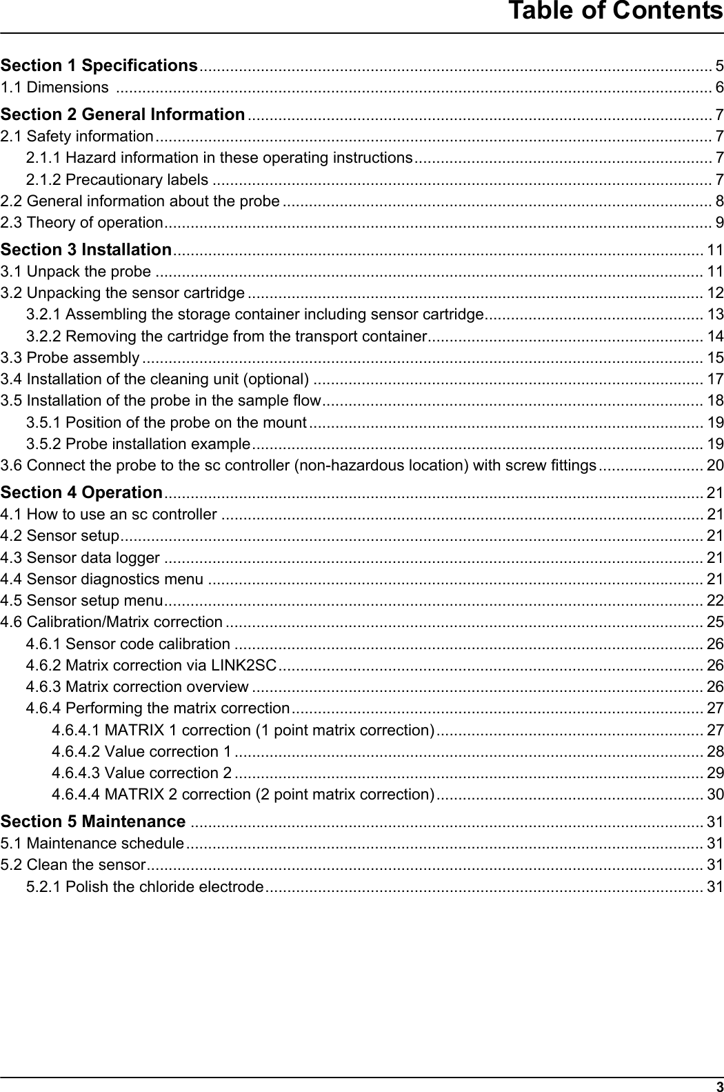
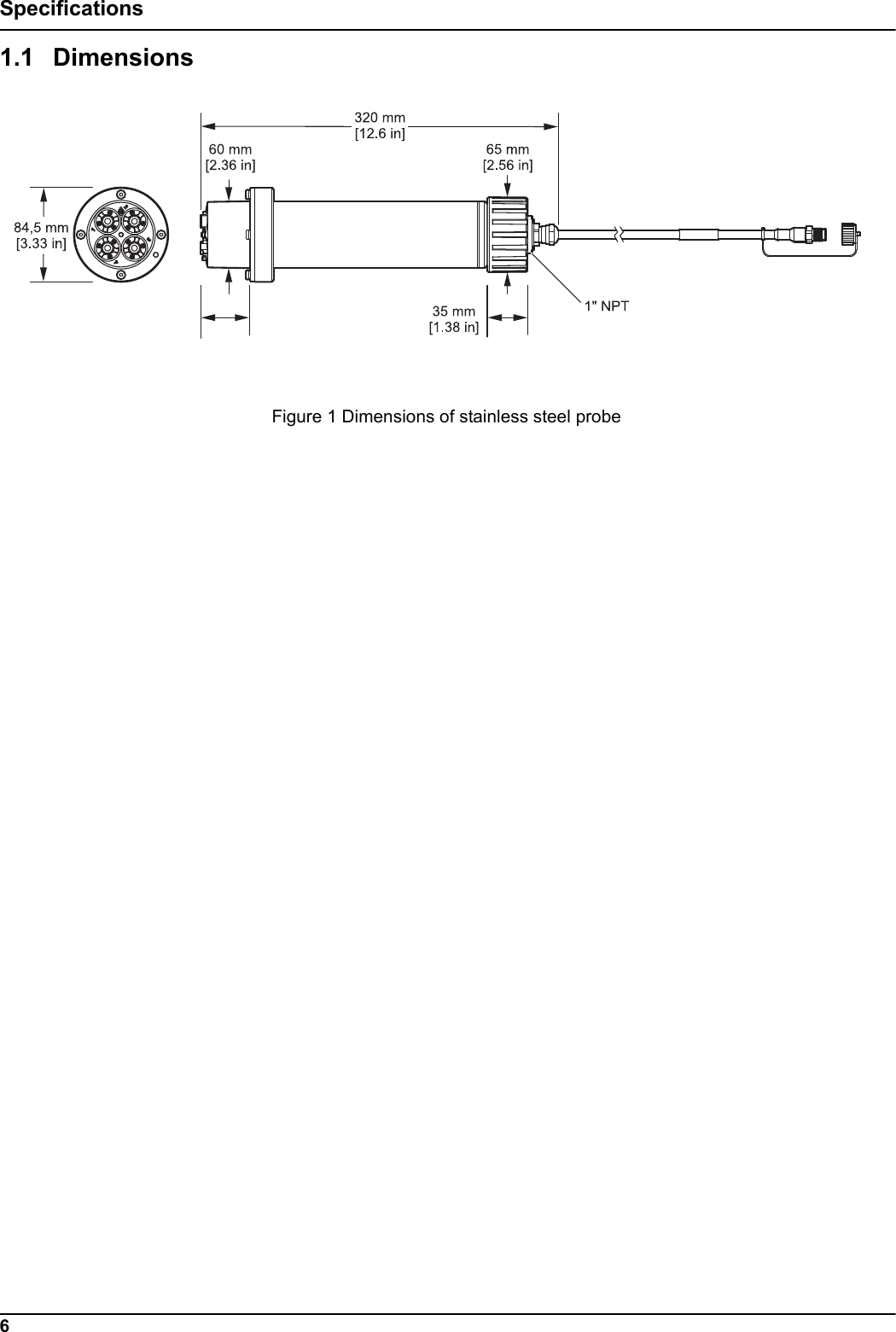
![5Section 1 SpecificationsThese are subject to change without notice.General InformationMeasuring method Potentiometric measurement using ion-selective electrodes (ISE) for ammonium, potassium, nitrate and chloride, reference systemMeasuring range0 to 1000 mg/L [NH4–N]0 to 1000 mg/L [K+]0 to 1000 mg/L [NO3–N]0 to 1000 mg/L [Cl–]Precision 5% of the measured value + 0.2 mg/L1 (ammonium and nitrate)Reproducibility 5% of the measured value + 0.2 mg/L1 (ammonium and nitrate)Response time (90 %) < 3 minutes (5 to 50 mg/L NO3–N/NH4–N)Measuring interval ContinuouspH range pH 5 to pH 9Calibration methods Sensor code for sensor cartridge 1 and 2 point value correction or matrix correctionPower consumption 1 WPower supply Via sc controllerData transfer Via sc controllerAmbient dataTypical environment Used in the biological phase of municipal wastewater treatmentStorage temperature Sensor: –20 to 60 °C (–4 to 140 °F)Sensor cartridge: 5 to 40 °C (41 to 104 °F)Operating temperature Air: –20 to 45 °C (–4 to 113 °F)Sample temperature +2 to 40 °C (35 to 104 °F)Max. Flow velocity < 4 m/sMax. sensor immersion depth/pressureCan be immersed at a depth of 0.3 to 3.0 m [1 to 10 ft]; maximum pressure: 0.3 bar (4.4 psi).Max. Compressed air output during cleaning unit operation 3.1 bar (45 psi)General information about the probeProbe dimensions 320 mm × 84.5 mm (12.6 × 3.3 in.) (Length × Ø)Refer to Figure 1, Page 6.Length of probe cableStandard: 10 m [33.8 ft]Extension cables are available as an option in the following lengths: 5, 10, 15, 20, 30, 50 m [16.4, 33.8, 49.2, 65.6, 98.4, 164 ft]. Maximum overall length: 100 m [328 ft]Probe weight Approximately 2380 g (63.6 oz)Wetted materialsOnly for immersed installations: Probe: stainless steel (1.4571), ASA + PC, silicon, PVC and PUSensor cartridge: PVC, POM, ABS, stainless steel (1.4571), NBROptional cleaning unit: TPE, PUR, stainless steel (1.4571)Installation angle 45° +/– 15° vertical in flow direction1 With standard solutions and ISE electrodes under laboratory conditions](https://usermanual.wiki/HACH-LANGE/LXG440/User-Guide-1530981-Page-5.png)

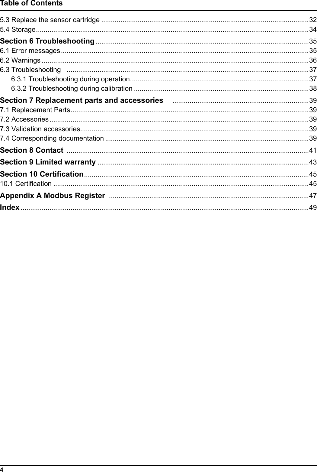
![47Appendix A Modbus Register Tag Name Register # Data Type Length R/W Discrete RangeMin/Max Range DescriptionAMMONIUM NH4-N 40001 Float 2 R 0/1500 AMMONIUM as NH4-N [mg/l]AMMONIUM NH4 40003 Float 2 R 0/1932 AMMONIUM as NH4 [mg/l]Nitrate NO3-N 40005 Float 2 R 0/1500 Nitrate as NO3-N [mg/l]Nitrate NO3 40007 Float 2 R 0/6643 Nitrate as NO3 [mg/l]Potassium 40009 Float 2 R 0/1500 Potassium [mg/l]Chloride 40011 Float 2 R 0/1500 Chloride [mg/l]TEMPERATURE [C] 40013 Float 2 R 0/60 TEMPERATURE [C]TEMPERATURE [F] 40015 Float 2 R -54/180 TEMPERATURE [F]Location 40025 String 8 R/W LocationMEAS UNITS 40033 Unsigned Integer 1 R/W U0/2 MEAS UNITS mg/l;ppmSET PARAMETER 40034 Unsigned Integer 1 R/W 0/1 NH4-N&NO3-N; NH4&NO3TEMP UNITS 40035 Unsigned Integer 1 R/W U25/26 °C; °FTEMP ADJUST [C] 40036 Float 2 R/W -1.5/1.5 TEMP ADJUST [C]TEMP ADJUST [F] 40038 Float 2 R/W -2.7/2.7 TEMP ADJUST [F]Response Interval 40040 Unsigned Integer 1 R/W 10/1800 Response IntervalLogger Interval 40041 Unsigned Integer 1R/W 0/1/2/3/4/5/6/7Logger IntervalK+ compensation 40042 Unsigned Integer 1 R/W 0/1 K+ compensation on/offK+ subsitute value 40043 Float 2 R/W 0/1500 K+ subsitute value if compensation is offChlorine compensation 40045 Unsigned Integer 1 R/W 0/1 Chlorine compensation on/offCl subsitute value 40046 Float 2 R/W 0/1500 Cl subsitute value if compensation is offSERIAL NUMBER 40049 String 6 R/W SERIAL NUMBERAC Code Version 40055 Float 2 R 0/3.40282347E+38AC Code VersionBC Code Version 40057 Float 2 R 0/3.40282347E+38BC Code VersionStructure DD 40059 Unsigned Integer 1 R 0/255 Structure DDContent DD 40060 Unsigned Integer 1 R 0/255 Content DDFirmware DD 40061 Unsigned Integer 1 R 0/255 Firmware DDMoist [%] 40062 Unsigned Integer 1 R 0/100 Moist [%] moisture in probe, OK<5%Ammonium mV 40063 Float 2 R -2000/2000 Ammonium mV](https://usermanual.wiki/HACH-LANGE/LXG440/User-Guide-1530981-Page-47.png)
![48Modbus RegisterAmmonium Drift 40065 Float 2 R -2000/2000 Ammonium DriftAmmonium Noise 40067 Float 2 R -2000/2000 Ammonium NoiseNitrate mV 40069 Float 2 R -2000/2000 Nitrate mVNitrate Drift 40071 Float 2 R -2000/2000 Nitrate DriftNitrate Noise 40073 Float 2 R -2000/2000 Nitrate NoisePotassium mV 40075 Float 2 R -2000/2000 Potassium mVPotassium Drift 40077 Float 2 R -2000/2000 Potassium DriftPotassium Noise 40079 Float 2 R -2000/2000 Potassium NoiseChloride mV 40081 Float 2 R -2000/2000 Chloride mVChloride Drift 40083 Float 2 R -2000/2000 Chloride DriftChloride Noise 40085 Float 2 R -2000/2000 Chloride NoiseReference mV 40087 Float 2 R -2000/2000 Reference mVReference Drift 40089 Float 2 R -2000/2000 Reference DriftReference Noise 40091 Float 2 R -2000/2000 Reference NoiseReference 2 [mV] 40093 Float 2 R -2000/2000 Reference 2 [mV]CART. NO. 40102 Unsigned Integer 2R 0/4294967295CART. NO.SENSORCODE 40104 String 8 R/W SENSORCODETag Name Register # Data Type Length R/W Discrete RangeMin/Max Range Description](https://usermanual.wiki/HACH-LANGE/LXG440/User-Guide-1530981-Page-48.png)