Hanchett Entry Systems KKSR100PA Aperio Cabinet Lock (K100-622-PA2), Aperio Server Cabinet Lock (KS100-640-PA2), Aperio Reader (R100-PA2) User Manual 3080076 004 C 052215 Draft
Hanchett Entry Systems, Inc. Aperio Cabinet Lock (K100-622-PA2), Aperio Server Cabinet Lock (KS100-640-PA2), Aperio Reader (R100-PA2) 3080076 004 C 052215 Draft
Users manual
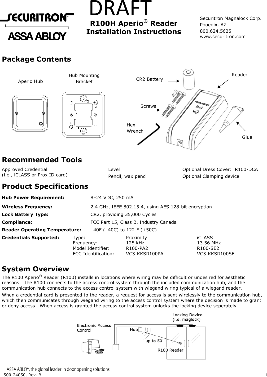
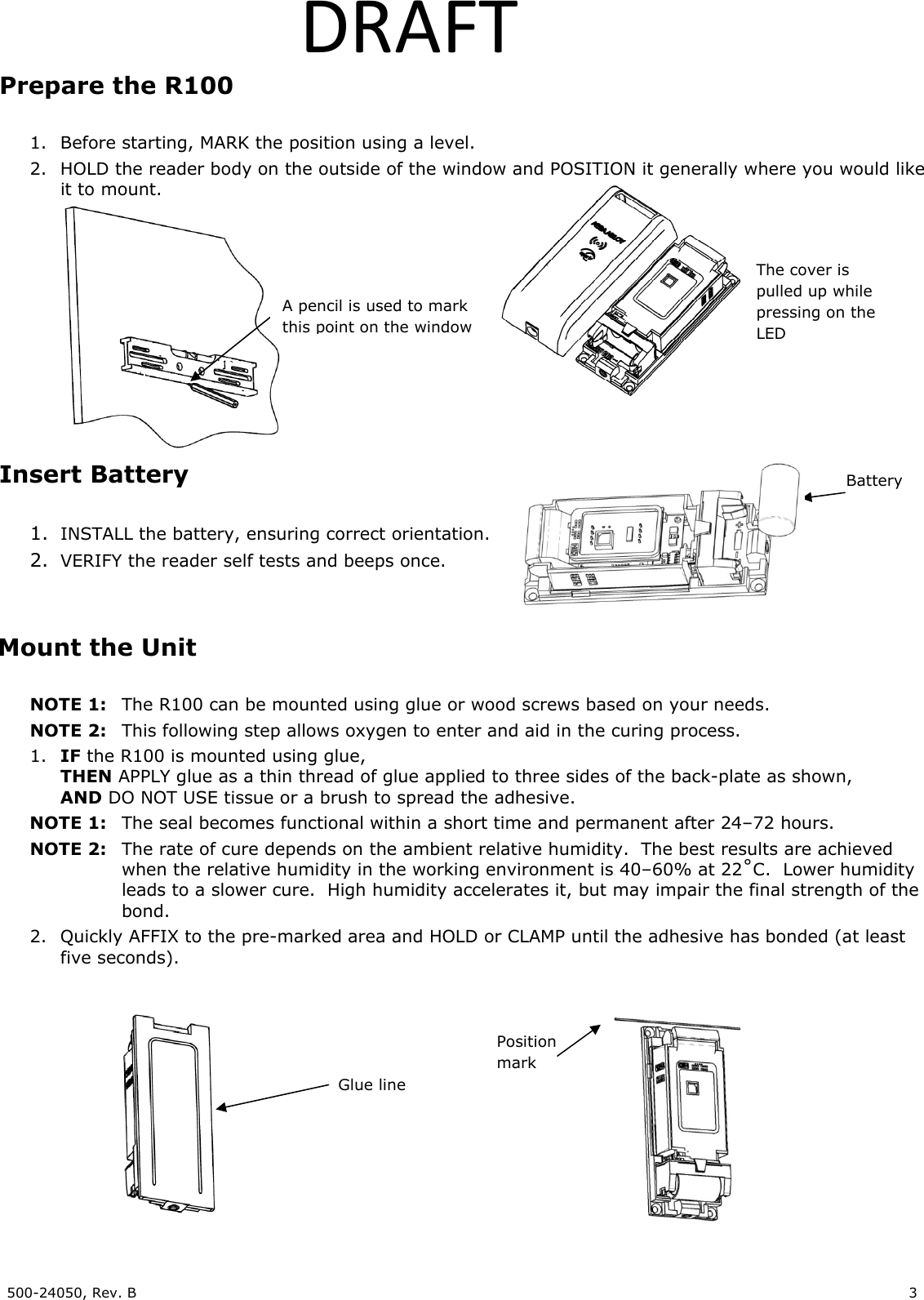
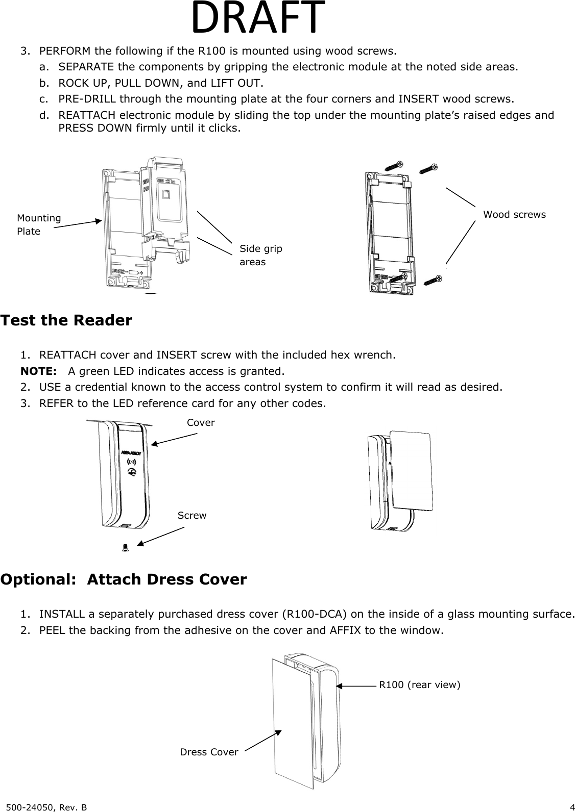
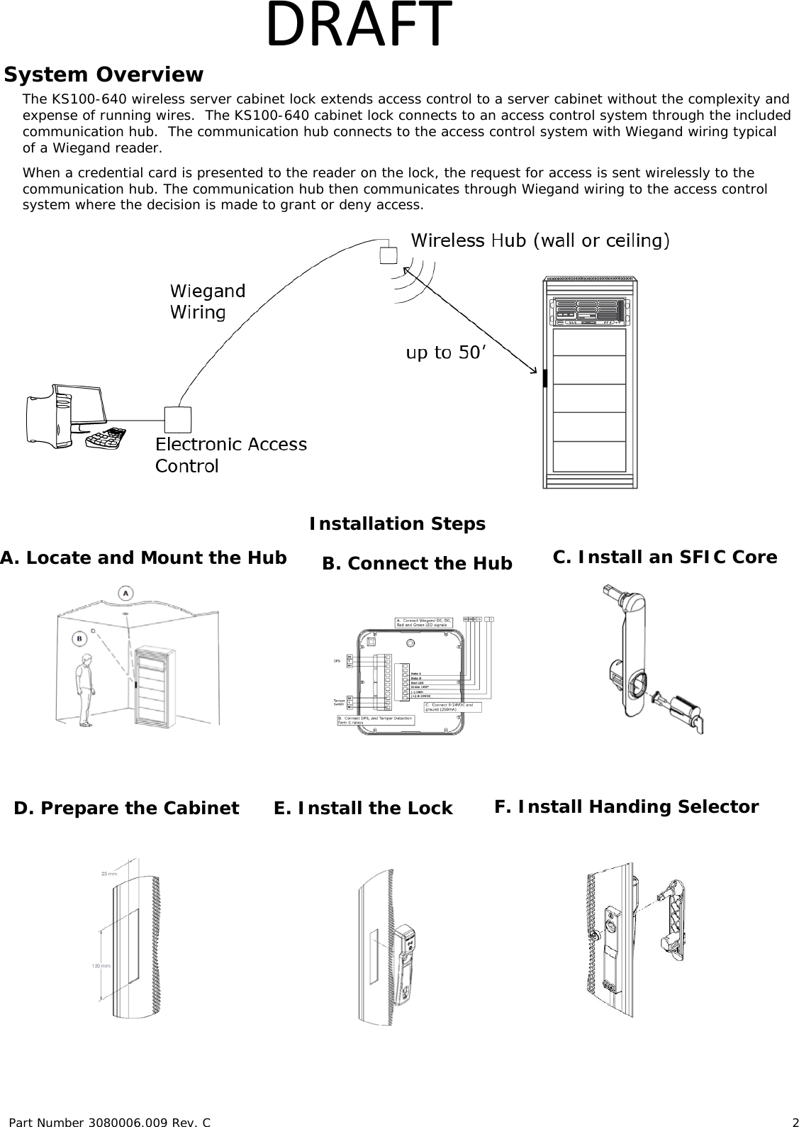
![ 3080076.004, Rev. C 1 DRAFT K100-622 Aperio® Cabinet Lock Installation Instructions HES, Inc. Phoenix, AZ 1.800.626.7590 www.hesinnovations.com Package Contents NOTE: The wireless hub and hub bracket are included with the K100-622H model. Recommended Tools Optional Additional Tools: Gang box to mount hub Cam Lock for Key Override Drill, Drill bits: 1/16” [1.59 mm], 3/16” [4.76 mm], 1/2” [12.70 mm] Approved iCLASS or Prox ID credential. Flathead drivers 3/32” [2.38 mm], 3/16” [4.76 mm], Phillips drivers (P0, P2), Pencil, Wire Stripper, Level, Square, Pliers Wireless Frequency: 2.4 GHz, IEEE 802.15.4, using AES 128-bit encryption Hub Power Requirement: 8–24 Volts Direct Current (VDC), 250 milliamps (mA) Lock Battery Type: Lithium AA Cell, 1.5 Volts (V) (Energizer L91 Ultimate Lithium) Battery Life: 50,000 cycles Operating Temperature: 32 °F to 122 °F [0 °C to 50 °C] Compliance: FCC Part 15, Class B, Industry Canada Credentials Supported: Type: Proximity iCLASS Frequency: 125 kHz 13.56 MHz Model Identifier: K100-622-PA2 K100-622-SE2 FCC Identification: VC3-KKSR100PA VC3-KKSR100SE IC Identification: 7160A-KKSR100622PA 7160A-KKSR100622SE Product Specifications Strike Plate Shaft Extension Energizer L91 Ultimate Lithium Batteries 2X Double door bracket Lock Body 8-32 x 1 3/4” [4.00 mm x 44.45 mm] Breakaway 3X 8-32 x 2 1/2” [4.00 mm x 63.50 mm] 2X 8-32 x 2 3/4” [4.00 mm x 69.85 mm] 2X 6-32 x 5/16” [3.5 mm x 7.94 mm] 3X 2-56 x 7/16” [M1.4 x 0.3 x 11.11 mm] 2X Key Override Cam Key Override Paddle Template Screws Reader 8-32 x 5/16” [4.00 mm x 7.94 mm] 1X Hub Bracket Wireless Hub In [mm] 2-56 x 1-1/4” [M1.4 x 0.3 x 31.50 mm] 1X 6 x 1/2” [3.50 mm x 12 mm] 5X](https://usermanual.wiki/Hanchett-Entry-Systems/KKSR100PA/User-Guide-2731740-Page-1.png)
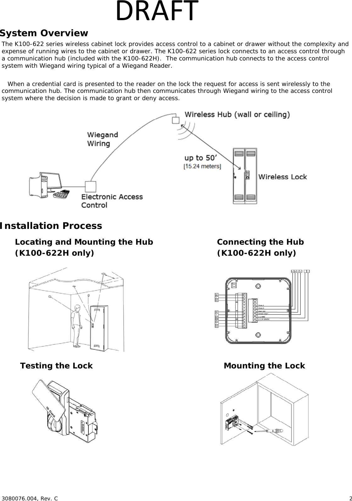
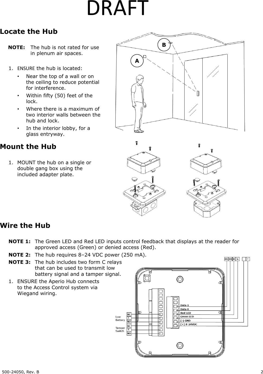
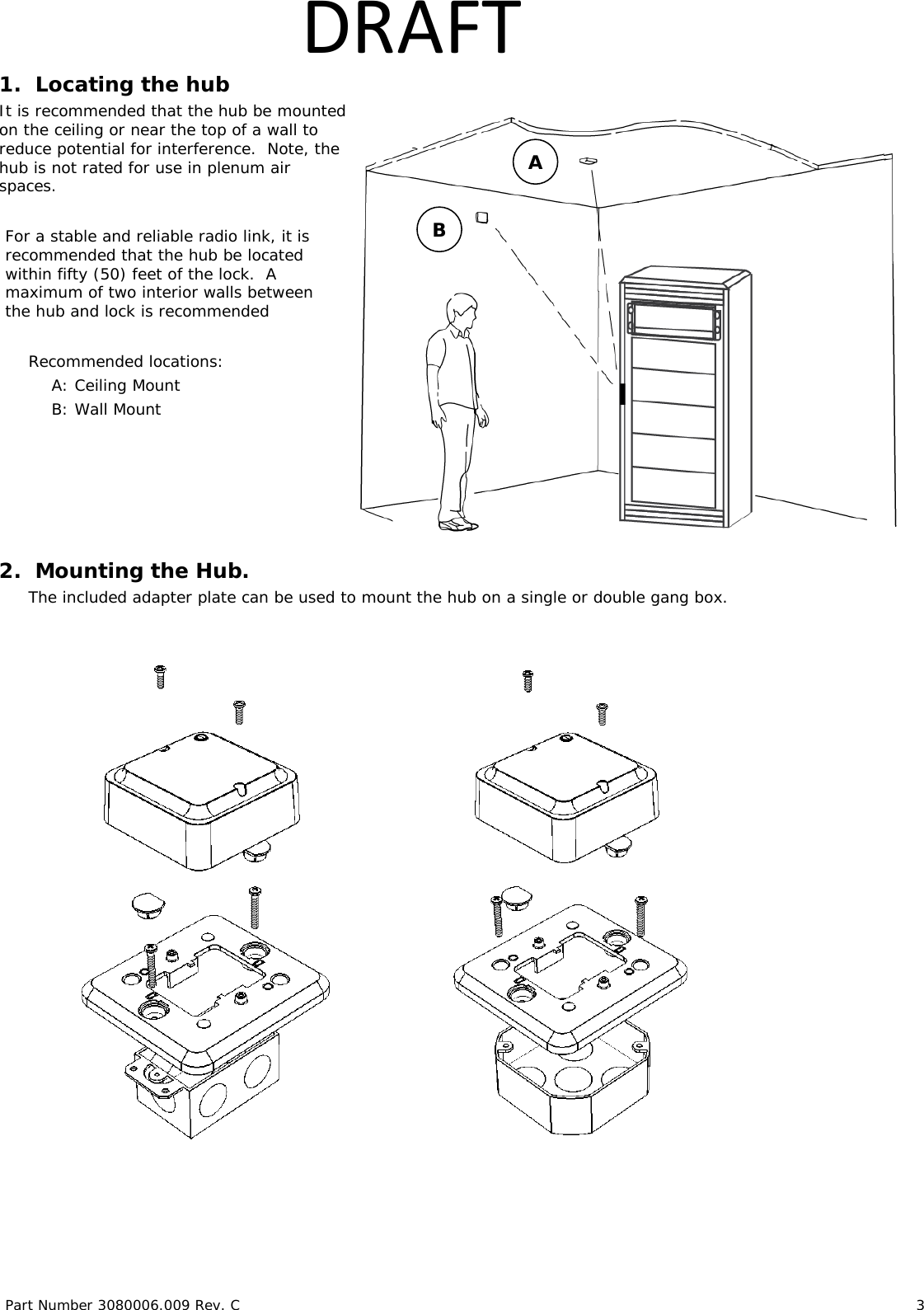
![ 3080076.004, Rev. C 3 DRAFTChoosing the hub location NOTE: The following applies primarily to the K100-622H Model with included hub. It is recommended that the hub be mounted near the top of a wall, on the ceiling or above the ceiling to reduce potential for interference, and be facing toward the lock for best performance. For a stable and reliable radio link, it is recommended that the hub is located within 50 feet [15.24 meters] of the lock. A maximum of two interior walls between the hub and lock is recommended Recommended locations: A: Wall Mount B: Ceiling Mount C: Wall Mount, Adjacent Room NOTE: The hub is not rated for use in plenum air spaces. Mounting the Hub NOTE: The following applies primarily to the K100-622H Model with included hub. The included adapter plate can be used to mount the hub on a single or double gang box. A B C](https://usermanual.wiki/Hanchett-Entry-Systems/KKSR100PA/User-Guide-2731740-Page-3.png)

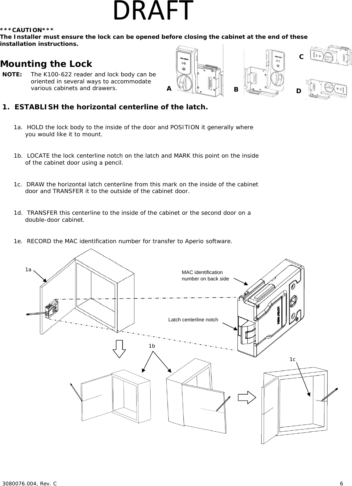
![ 3080076.004, Rev. C 7 DRAFT2. TRANSFER the location of the inside wall of the cabinet to the door. 2a. MEASURE the horizontal distance between the inside edge of the cabinet and the door edge. NOTE: The drawn line depicts the location of the strike mounting surface. 2b. DRAW a line on the outside surface of the door, using the same distance away from the door edge. 3. PLACE and USE the Lock/Reader Template. NOTE: Orientation will be reversed for a right hand door. 3a. CUT through line to separate the Strike Plate Template. 3b. PEEL OFF the protective layer of the Lock Template, ALIGN it to both the latch centerline and the line depicting the inside wall of cabinet, and PRESS to secure. NOTE: Two of the holes in the following step are 3/16” [4.76 mm] diameter and two are 1/2” [12.70 mm] diameter. The two pilot holes are 1/16” [1.59 mm]. 3c. DRILL four holes and two pilot holes through the cabinet, as shown in the figure below. 3d. DRILL only one 3/16” [4.76 mm] hole depending on the desired Antenna/Reader orientation. 3e. IF the optional key override will be installed, THEN GO TO Step 5. 3f. REMOVE the lock template from the door. Cabinet/door front viewDoor edge 2a 2b 3a 3b, 3c, 3d](https://usermanual.wiki/Hanchett-Entry-Systems/KKSR100PA/User-Guide-2731740-Page-7.png)
![ 3080076.004, Rev. C 8 DRAFT4. INSTALL the Shaft Extension. 4a. IF the cabinet door thickness is greater than ½” [12.70 mm], THEN INSTALL the Shaft Extension to the Antenna/Reader to ensure proper engagement into the lock. 4b. INSTALL the Shaft Extension to the shaft as shown in the figure and firmly TIGHTEN the screw. Door Thickness Extension Shaft Used? 1/16” [1.59 mm] – ½” [12.70 mm] No > ½” [12.70 mm] – 1 ½” [38.10 mm] Yes 5. IF a Cam Lock Key Override will be used, AND the orientation allows for installation, THEN INSTALL the Key Override Paddle. 5a. INSERT the Paddle’s arm into the opening shown, and ALIGN the rails of the paddle to the ones on the lock. 5b. SLIDE the paddle gently until it stops. 6. PREPARE the Key Override Door. NOTE: The Cam Lock is optional and must be obtained by others. 6a. IF a Key Override is used, THEN USE template to mark and drill a hole for a 3/4” [19.05 mm] Cam Lock in the door. Shaft Extension 2-56 X 1-¼” [M1.4 x 0.3 x 31.50 mm] screw (provided) Table15b 6a 6b. INSTALL the optional Cam Lock with the cabinet lock as shown in the figure. 6b 5a](https://usermanual.wiki/Hanchett-Entry-Systems/KKSR100PA/User-Guide-2731740-Page-8.png)
![ 3080076.004, Rev. C 9 DRAFT7. INSTALL the Antenna/Reader. ***CAUTION*** Pinching the wires may prevent the Reader and Lock from properly functioning. 7a. PLACE and HOLD the antenna/reader to the outside of cabinet, routing the wire through the 1/2” [12.70 mm] offset hole, and ENSURE the knob is in the locked position in the vertical. NOTE: Using the Table 2 below will help determine the length of the top mount screw needed, based on the thickness of the cabinet door. 7b. INSTALL the top mount screw to attach the antenna/reader to the outside case. Reader mounting screw. 7a 7b Table 2](https://usermanual.wiki/Hanchett-Entry-Systems/KKSR100PA/User-Guide-2731740-Page-9.png)
![ 3080076.004, Rev. C 10 DRAFT8. INSTALL the lock. 8a. REMOVE the battery cover from lock. 8b. PLACE the lock on the inside of the door, threading the cable through the lock. 8b. ATTACH the lock to the antenna/reader using two 8-32 [4.00 mm] lock mount screws (see Table 2 for length), and TIGHTEN the screws. 8c. INSTALL the two #6 self-threading screws and TIGHTEN. NOTE: The third #6 self-threading screw is important to achieve maximum holding force for doors greater than 5/8” [15.88 mm] thick. 8d. INSTALL the third #6 self-threading screw only if the door is more than 5/8” [15.88 mm] thick, using the lock as a guide, and TIGHTEN. 9. Electrically CONNECT the antenna/reader wire to the lock body. NOTE: The antenna/reader wire connector is keyed to only fit one way. 9a. ENSURE correct orientation of the connector while inserting it. 9b. TUCK excess cable into lock body as shown. 9a 9b Connector cable tucked in Cable is threaded through the hole in the lock. 8a Used only for doors less than 5/8” thick. 8b 8c 8d](https://usermanual.wiki/Hanchett-Entry-Systems/KKSR100PA/User-Guide-2731740-Page-10.png)

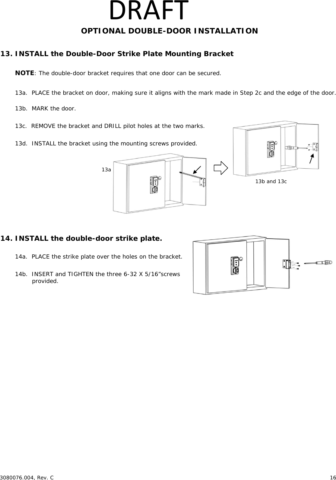
![ 3080076.004, Rev. C 12 DRAFTOPTIONAL DOUBLE-DOOR INSTALLATION 13. INSTALL the Double-Door Strike Plate Mounting Bracket NOTE: The double-door bracket requires that one door can be secured. 13a. PLACE the bracket on door, making sure it aligns with the mark made in Step 2c and the edge of the door. 13b. MARK the door. 13c. REMOVE the bracket and DRILL pilot holes at the two marks. 13d. INSTALL the bracket using the mounting screws provided. 14. INSTALL the double-door strike plate. 14a. PLACE the strike plate over the holes on the bracket. 14b. INSERT and TIGHTEN the three 6-32 X 5/16”screws provided. 4. INSTALL the Shaft Extension. 4a. IF the cabinet door thickness is greater than ½” [12.70 mm], THEN INSTALL the Shaft Extension to the Antenna/Reader to ensure proper engagement into the lock. 4b. INSTALL the Shaft Extension to the shaft as shown in the figure and firmly TIGHTEN the screw. Door Thickness Extension Shaft Used? 1/16” [1.59 mm] – ½” [12.70 mm] No > ½” [12.70 mm] – 1 ½” [38.10 mm] Yes 5. IF a Cam Lock Key Override will be used, AND the orientation allows for installation, THEN INSTALL the Key Override Paddle. 5a. INSERT the Paddle’s arm into the opening shown, and ALIGN the rails of the paddle to the ones on the lock. 5b. SLIDE the paddle gently until it stops. 6. PREPARE the Key Override Door. NOTE: The Cam Lock is optional and must be obtained by others. 6a. IF a Key Override is used, THEN USE template to mark and drill a hole for a 3/4” [19.05 mm] Cam Lock in the door. Shaft Extension 2-56 X 1-¼” [M1.4 x 0.3 x 31.50 mm] screw (provided) Table113a 13b and 13c 5b 6a 6b. INSTALL the optional Cam Lock with the cabinet lock as shown in the figure. 6b 5a](https://usermanual.wiki/Hanchett-Entry-Systems/KKSR100PA/User-Guide-2731740-Page-12.png)
![ 3080076.004, Rev. C 13 DRAFT7. INSTALL the Antenna/Reader. ***CAUTION*** Pinching the wires may prevent the Reader and Lock from properly functioning. 7a. PLACE and HOLD the antenna/reader to the outside of cabinet, routing the wire through the 1/2” [12.70 mm] offset hole, and ENSURE the knob is in the locked position in the vertical. NOTE: Using the Table 2 below will help determine the length of the top mount screw needed, based on the thickness of the cabinet door. 7b. INSTALL the top mount screw to attach the antenna/reader to the outside case. Reader mounting screw. 7a 7b Table 2](https://usermanual.wiki/Hanchett-Entry-Systems/KKSR100PA/User-Guide-2731740-Page-13.png)
![ 3080076.004, Rev. C 14 DRAFT8. INSTALL the lock. 8a. REMOVE the battery cover from lock. 8b. PLACE the lock on the inside of the door, threading the cable through the lock. 8b. ATTACH the lock to the antenna/reader using two 8-32 [4.00 mm] lock mount screws (see Table 2 for length), and TIGHTEN the screws. 8c. INSTALL the two #6 self-threading screws and TIGHTEN. NOTE: The third #6 self-threading screw is important to achieve maximum holding force for doors greater than 5/8” [15.88 mm] thick. 8d. INSTALL the third #6 self-threading screw only if the door is more than 5/8” [15.88 mm] thick, using the lock as a guide, and TIGHTEN. 9. Electrically CONNECT the antenna/reader wire to the lock body. NOTE: The antenna/reader wire connector is keyed to only fit one way. 9a. ENSURE correct orientation of the connector while inserting it. 9b. TUCK excess cable into lock body as shown. 9a 9b Connector cable tucked in Cable is threaded through the hole in the lock. 8a Used only for doors less than 5/8” thick. 8b 8c 8d](https://usermanual.wiki/Hanchett-Entry-Systems/KKSR100PA/User-Guide-2731740-Page-14.png)

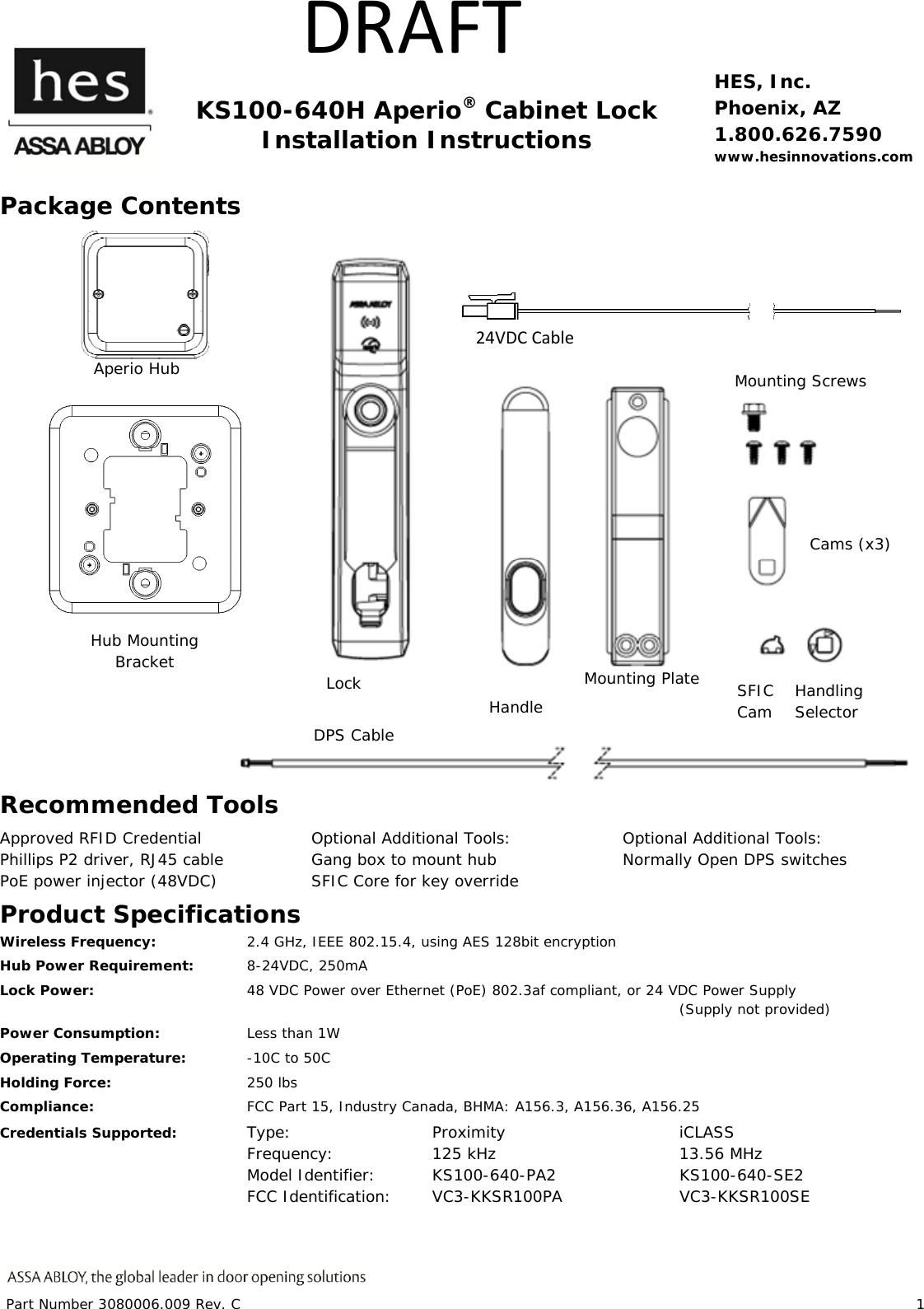

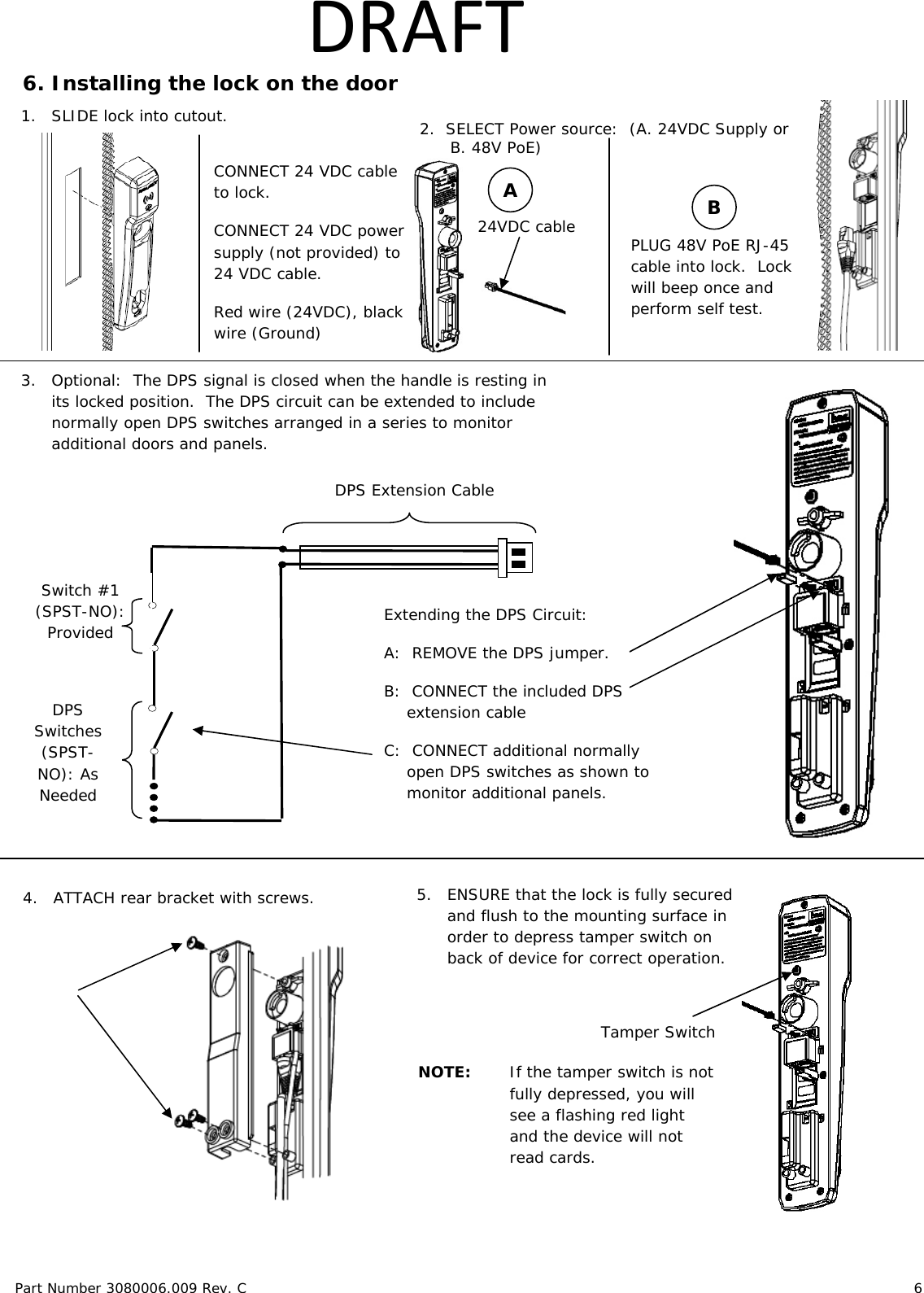
![Part Number 3080006.009 Rev. C 5 DRAFT 5. Preparing the Rack LOCATE the 25mm x 150mm lock cutout on the door, some doors may require modification. 1. VERIFY 48V POE power is available at the rack. 2. RE_USE the existing cam if possible. 3. Three cams are supplied. CAM CAM LENGTH CAM DEPTH CAM 1 38mm [1-1/2"] 16mm [5/8"] CAM 2 38mm [1-1/2"] 24mm [15/16"] CAM 3 45mm [1-3/4"] 22.5mm [7/8"] 1. REMOVE plug from handle 3. INSERT SFIC into lock 7-pin 2. INSERT cam into SFIC using the included spacers with 6-pin SFICs. 6-pin](https://usermanual.wiki/Hanchett-Entry-Systems/KKSR100PA/User-Guide-2731740-Page-22.png)