Hanchett Entry Systems RF5X10 HES Hybrid Electric Strike User Manual users manual
Hanchett Entry Systems, Inc. HES Hybrid Electric Strike users manual
UserManual.wiki
>
Hanchett Entry Systems
>
RF5X10 User Manual
users manual
Navigation menu
Upload a User Manual
Namespaces
Wiki Guide
HTML
PDF
Info
Views
User Manual
Discussion / Help
Navigation
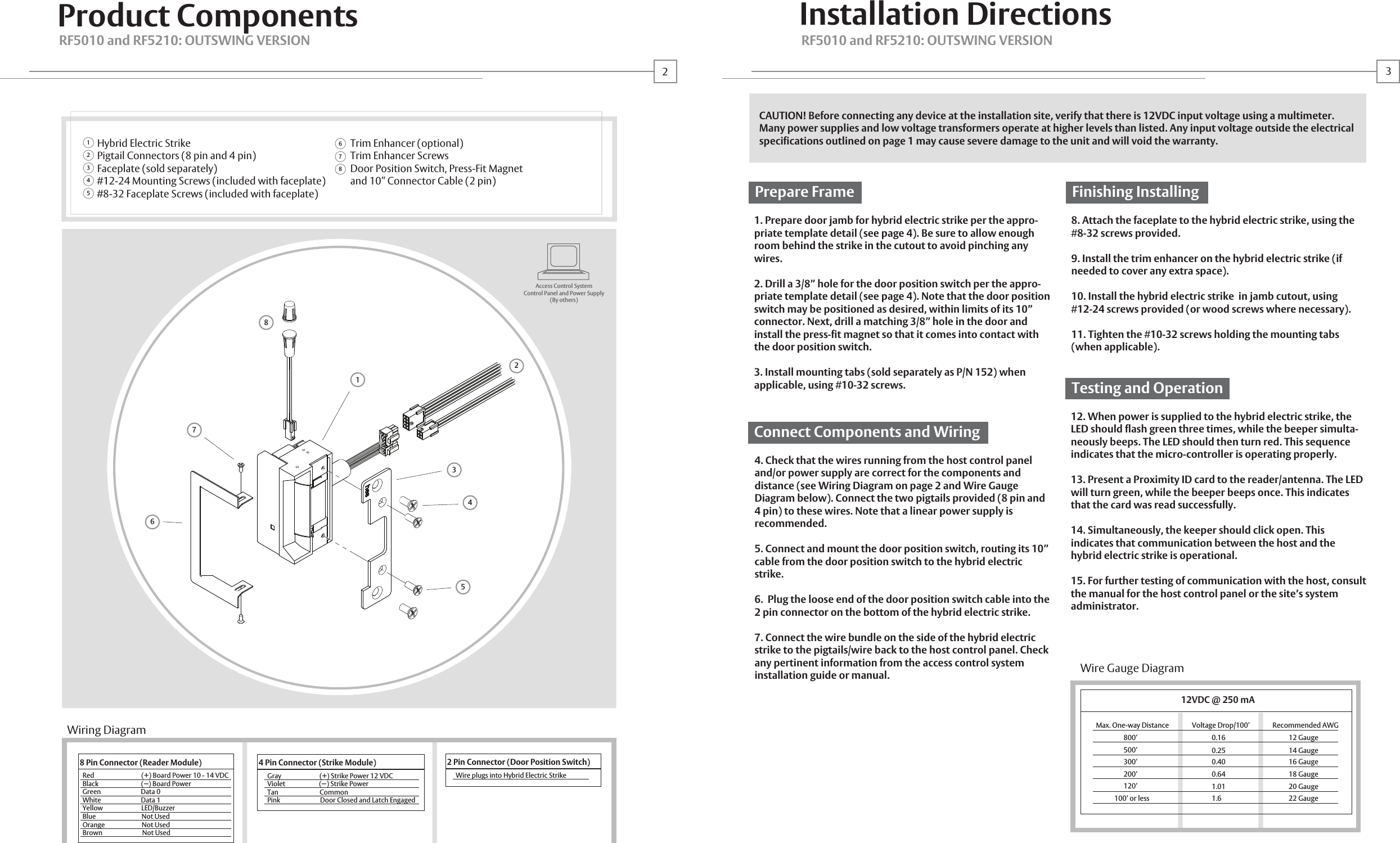
![Steel, Aluminum, WoodIncludedCylindricalRF5010: Accomodates up to 5/8" LatchboltRF5210: Accomodates up to 3/4" LatchboltNot Recommended for Outdoor use32 F 150 F (0 C 65 C)5 95%, Non-condensing®RF5010 and RF5210Installation InstructionsCutout TemplateOutswing VersionProductDescriptionDimensionsOrientationCompatibility Access Control Systems Proximity Cards FrequencyIndicatorsSupervisionIntegrated Electric Strike and Proximity Card ReaderSee page 4Non-handed, ReversibleOpen ArchitectureInterfaces with Wiegand Protocol Systems Supports HID 26 39 Bit FormatsSupports HID 125 KHz CredentialsRed/Green LED and BuzzerDoor Position Switch and Latchbolt MonitorCable DetailReader Module Distance to Host Recommended TypeElectric Strike Module Distance to Power Recommended Type500 ft. Max. 18 22 AWG (Dependent on Distance) Stranded and Shielded See Page 3See Page 3CertificationsComplianceSecurityFCC Part 15 (USA and Canada)UL 1034, Burglary-Resistant ListedANSI/BHMA 156.31, Grade 1MEA New York City AcceptedWarrantyLifetime WarantyHYBRID ELECTRIC STRIKES: OUTSWING VERSIONRF5010 and RF52010: OUTSWING VERSIONHES, Inc.22630 N. 17th Ave.Phoenix, AZ 85027800-626-7590© 2007 HES, Inc.0000000000.002 rev ADoor Position Switch Hybrid Electric Strike®ElectricalReader Module Operating Voltage 10 14VDC Operating Current 125 mA Max. at 12VDCElectric Strike Module 250mA @12VDCApplicationsFrames Trim EnhancerLocks Latchbolts Released*Environment Temperature HumidityHID is a registered trademark of HID Corporation.14*Faceplate options accommodate various keeper and latchbolt actions. For more detail, contact HES tech support at 800-626-75903 -3/8"8643461-1/4"324 -7/8"1244 -1/8"1053/8"10RF5010: 11/16"RF5210: 13/16"1-1/4” x 4-7/8” Square Corner FaceplateANSI Metal Jamb InstallationRF5010 or RF5210 with 501 FaceplateWarning: Changes or modification to this device not expressly approved by HES, Inc. could void the user’s authority to operate the equipment.NOTE: This equipment has been tested and found to comply with the limits for a class [B] digital device, pursuant to Part 15 of the FCC Rules. These limits are designed to provide reasonable protection against harmful interference in a residential installation. This equipment generates, uses, and can radiate radio frequency energy and, if not installed and used in accordance with the instructions, may cause harmful interference to radio communications. However, there is no guarantee that interference will not occur in a particular installation. If this equipment does cause harmful interference to radio or television reception, which can be determined by turning the equipment off and on, the user is encouraged to try to correct the interference by one or more of the following measures: Reorient or relocate the receiving antenna. Increase the separation between the equipment and receiver. Connect the equipment into an outlet on a circuit different from that to which the receiver is connected. Consult the dealer or an experienced radio/TV technician for helpThis class [B] digital apparatus meets all requirements of the Canadian interference Causing Equipment Regulations. Operation is subject to the following two conditions: (1) this device may not cause harmful interference, and (2) this device must accept any interference received, including interference that may cause undesired operation.Cet appareillage numérique de la classe [B] répond à toutes les exigences de l’inerférencé canadienne causant des réglements d’équipement. L’opération est sujette aux deux conditions suivantes: (1) ce dispositif peut ne pas causer l’interférence nocive, et (2) ce dispositif doit accepter n’importe quelle interférence reçue, y compris l’interférence qui peut causer l’opération peu désirée.](https://usermanual.wiki/Hanchett-Entry-Systems/RF5X10/User-Guide-808567-Page-2.png)
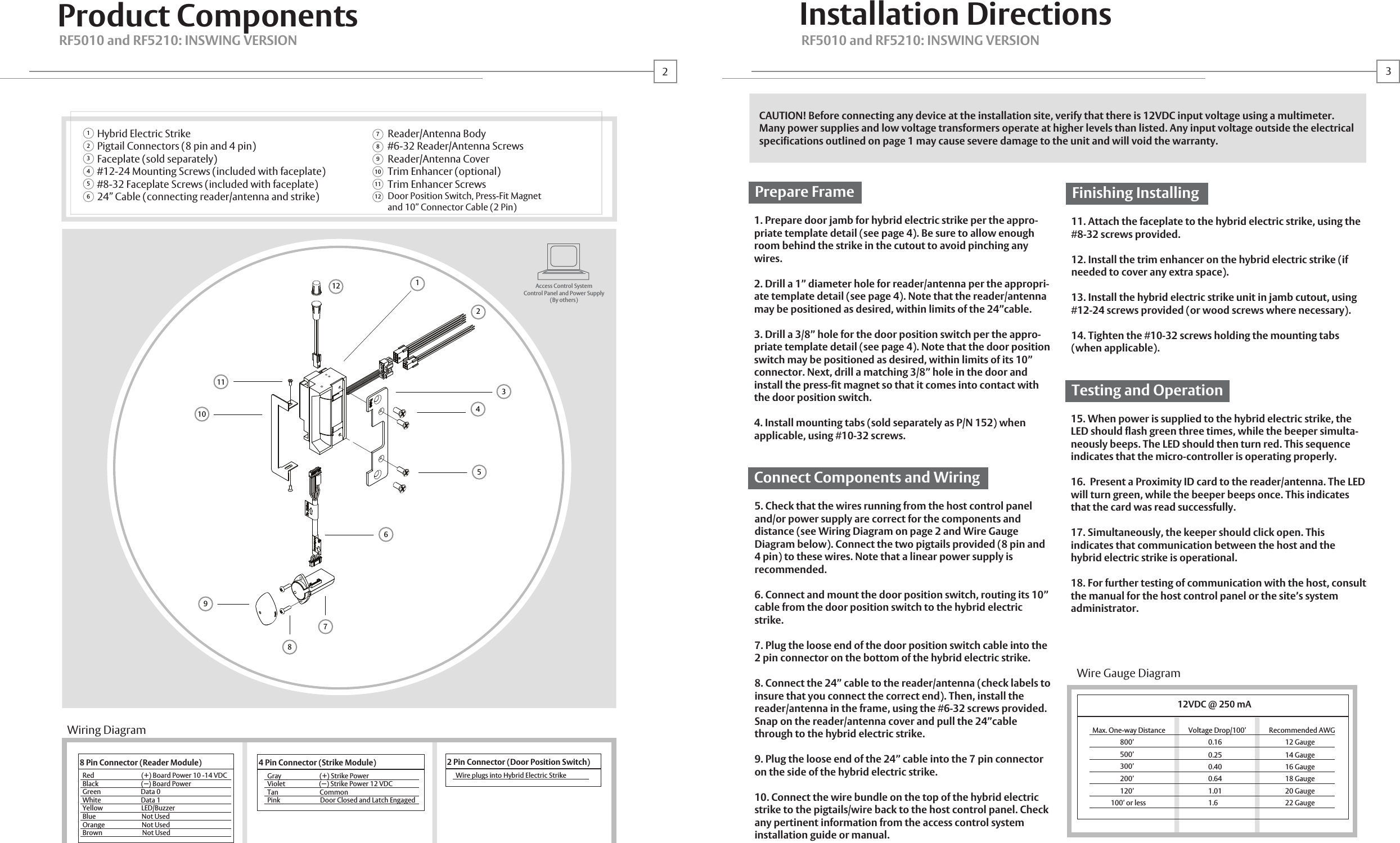
![®RF5010 and RF52101-1/4” x 4-7/8” Square Corner FaceplateANSI Metal Jamb InstallationRF5000 or RF5200 with 501 Faceplate1-1/4” x 4-7/8” Square Corner FaceplateANSI Metal Jamb InstallationRF5000 or RF5200 with 501 FaceplateInstallation InstructionsCutout TemplateProductApplicationsElectricalCable detailCertificationsWarrantyDescriptionDimensionsOrientationCompatibility Access Control Systems Proximity Cards FrequencyIndicatorsSupervisionElectric Strike and Proximity Card Reader withAntenna Module Mounted Separately in FrameSee page 4Non handed, ReversibleOpen ArchitectureInterfaces with Wiegand Protocol Systems Supports HID 26 39 Bit FormatsSupports HID 125 KHz CredentialsRed/Green LED and BuzzerDoor Position Switch and Latchbolt MonitorFrames Trim EnhancerLocks Latchbolts Released*Environment Temperature HumiditySteel, Aluminum, WoodIncludedCylindricalRF5010: Accomodates up to 5/8" LatchboltRF5210: Accomodates up to 3/4" LatchboltSuitable for Exterior Doors32 F 150 F (0 C 65 C)5 95%, Non-condensingReader Module Distance to Host Recommended TypeElectric Strike Module Distance to Power Recommended Type500 ft. Max. 18 22 AWG (Dependent on Distance) Stranded and Shielded See Page 3See Page 3ComplianceSecurity FCC Part 15 (USA and Canada)UL 1034, Burglary-Resistant ListedANSI/BHMA 156.31, Grade 1MEA New York City AcceptedLifetime WarantyInswing VersionHYBRID ELECTRIC STRIKES: INSWING VERSIONHYBRID ELECTRIC STRIKES: INSWING VERSIONHES, Inc.22630 N. 17th Ave.Phoenix, AZ 85027800-626-75903 -3/8"86RF5010: 11/16"RF5210: 13/16" 211-1/4"324- 7/8"1244-1/8"1053/8"101"1-5/16"335/8"172517© 2007 HES, Inc.0000000000.001 rev AReader/Antenna Door Position Switch Hybrid Electric Strike®Reader Module Operating Voltage 10 14VDC Operating Current 125 mA Max. at 12VDCElectric Strike Module 250mA @12VDCHID is a registered trademark of HID Corporation.14*Faceplate options accommodate various keeper and latchbolt actions. For more detail, contact HES tech support at 800-626-75901-1/4” x 4-7/8” Square Corner FaceplateANSI Metal Jamb InstallationRF5010 or RF5210 with 501 FaceplateWarning: Changes or modification to this device not expressly approved by HES, Inc. could void the user’s authority to operate the equipment.NOTE: This equipment has been tested and found to comply with the limits for a class [B] digital device, pursuant to Part 15 of the FCC Rules. These limits are designed to provide reasonable protection against harmful interference in a residential installation. This equipment generates, uses, and can radiate radio frequency energy and, if not installed and used in accordance with the instructions, may cause harmful interference to radio communications. However, there is no guarantee that interference will not occur in a particular installation. If this equipment does cause harmful interference to radio or television reception, which can be determined by turning the equipment off and on, the user is encouraged to try to correct the interference by one or more of the following measures: Reorient or relocate the receiving antenna. Increase the separation between the equipment and receiver. Connect the equipment into an outlet on a circuit different from that to which the receiver is connected. Consult the dealer or an experienced radio/TV technician for helpThis class [B] digital apparatus meets all requirements of the Canadian interference Causing Equipment Regulations. Operation is subject to the following two conditions: (1) this device may not cause harmful interference, and (2) this device must accept any interference received, including interference that may cause undesired operation.Cet appareillage numérique de la classe [B] répond à toutes les exigences de l’inerférencé canadienne causant des réglements d’équipement. L’opération est sujette aux deux conditions suivantes: (1) ce dispositif peut ne pas causer l’interférence nocive, et (2) ce dispositif doit accepter n’importe quelle interférence reçue, y compris l’interférence qui peut causer l’opération peu désirée.](https://usermanual.wiki/Hanchett-Entry-Systems/RF5X10/User-Guide-808567-Page-4.png)