Hanchett Entry Systems XX20 HES Hybrid Electric Strike iCLASS User Manual ic5020 ic5220 1 8
Hanchett Entry Systems, Inc. HES Hybrid Electric Strike iCLASS ic5020 ic5220 1 8
UserManual.wiki
>
Hanchett Entry Systems
>
XX20 User Manual
Installation Instructions
Navigation menu
Upload a User Manual
Namespaces
Wiki Guide
HTML
PDF
Info
Views
User Manual
Discussion / Help
Navigation
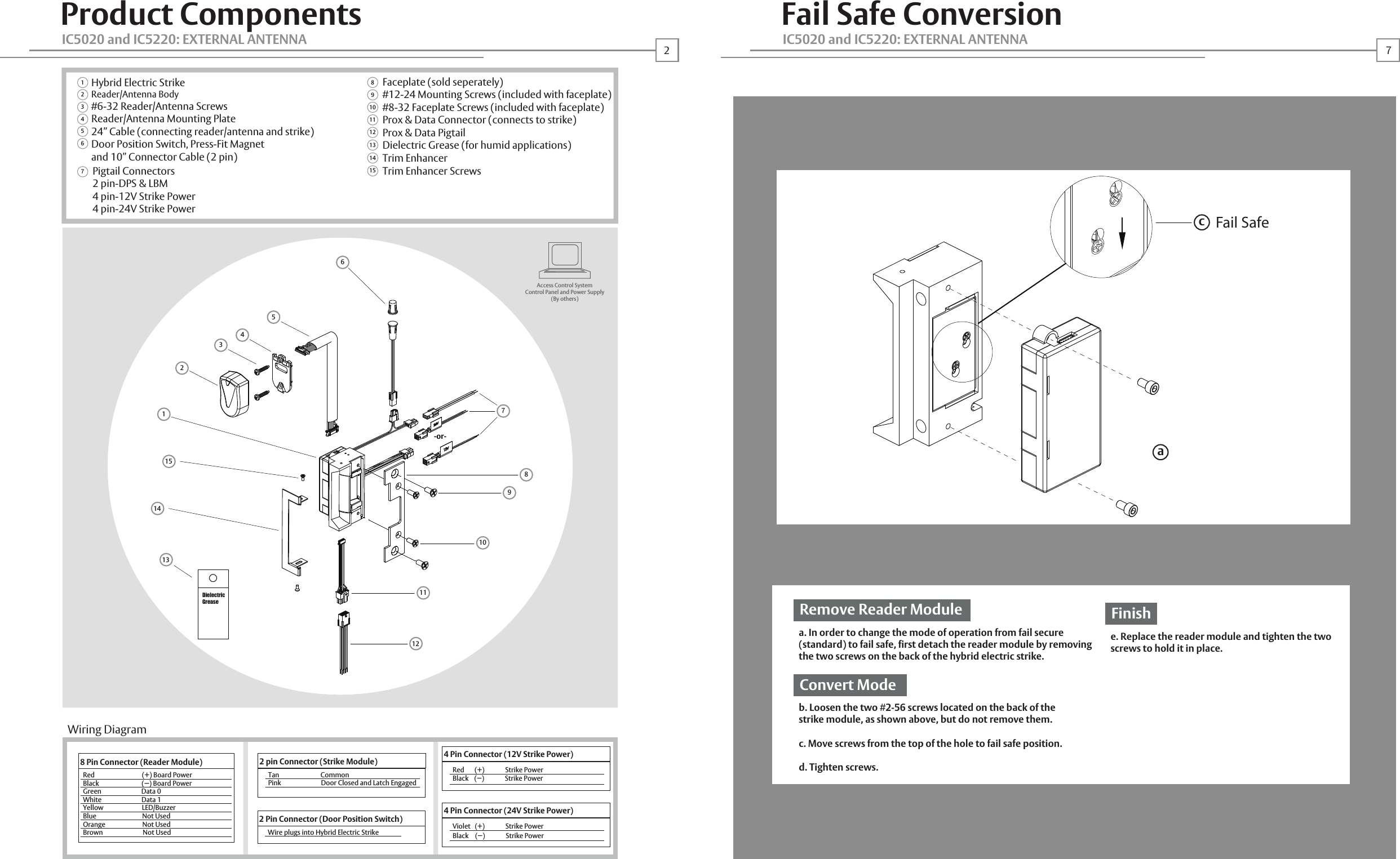
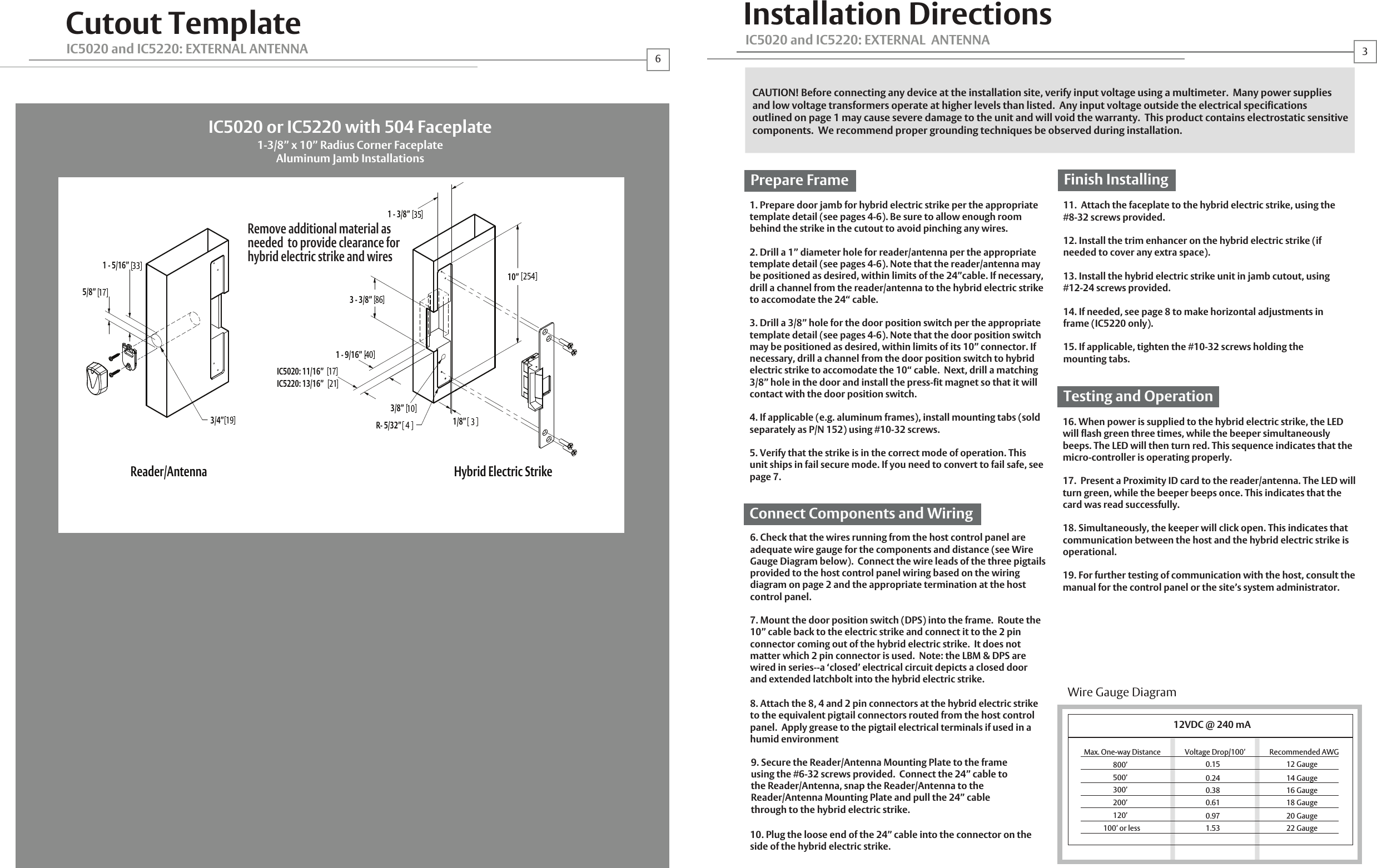
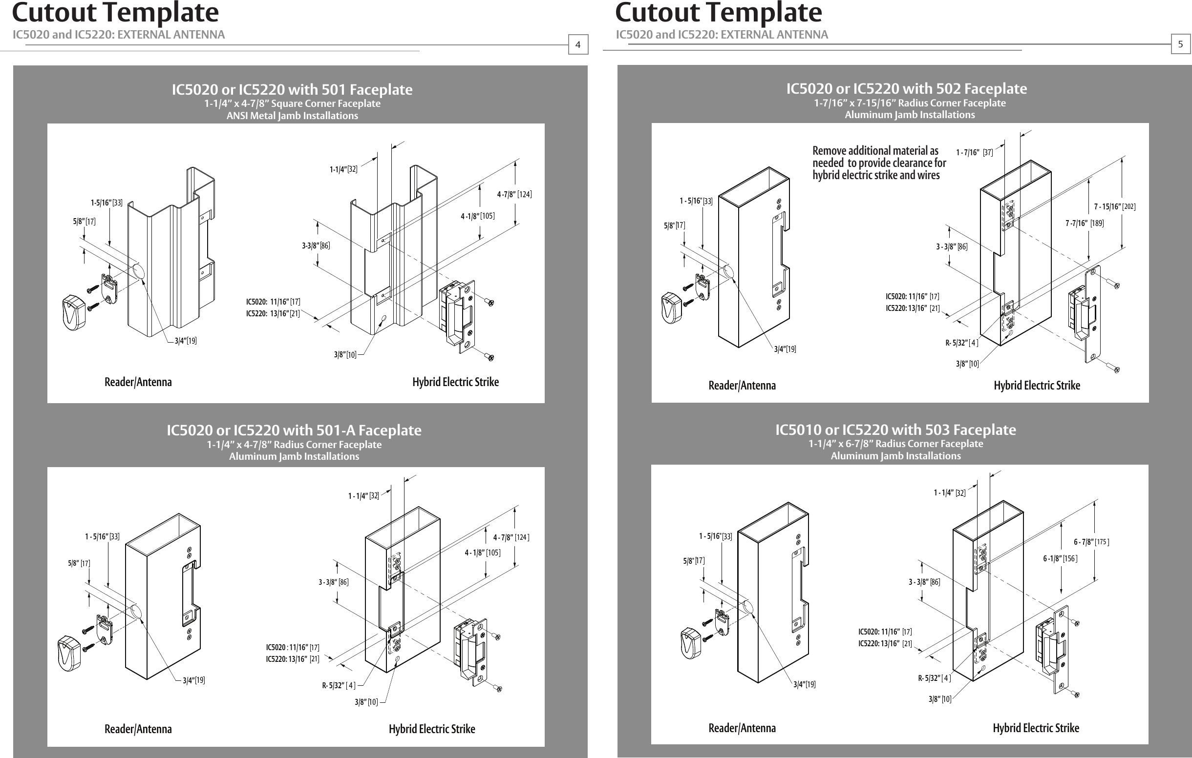
![IC5020 and IC5220Installation InstructionsHorizontal AdjustabilityProductApplicationsElectricalCable detailCertificationsWarrantyDescriptionDimensionsOrientationCompatibility Access Control SystemsProximity CardsFrequencyIndicatorsSupervisionElectric Strike and Proximity Card Reader withAntenna Module Mounted Separately in FrameSee pages 4-6Non handedOpen ArchitectureInterfaces with Wiegand Protocol Systems Supports HID 26, 32, 34, 37, 40 & 56 Bit FormatsSupports HID 13.56 MHz CredentialsRed/Green LED and BuzzerDoor Position Switch and Latchbolt MonitorFrames Trim EnhancerLocksLatchbolts Released*Environment TemperatureHumiditySteel, AluminumIncludedCylindricalIC5020: Accomodates up to 5/8" LatchboltIC5220: Accomodates up to 3/4" LatchboltSuitable for Exterior Doors32 F 150 F (0 C 65 C)5 95%, Non-condensingReader Module Distance to Host Recommended TypeElectric Strike Module Distance to Power Recommended Type500 ft. Max. 18 22 AWG (Dependent on Distance) Stranded and Shielded See Page 3See Page 3ComplianceSecurityFCC Part 15/IC Class BANSI/BHMA 156.31, Grade 1Lifetime Waranty against defectsin materials and workmanshipIC5020 and IC5220: EXTERNAL ANTENNAIC5220 (ONLY): HES, Inc.22630 N. 17th Ave.Phoenix, AZ 85027800-626-7590©2010 HES, Inc.3065006.001 rev A1Reader Module Operating Voltage 12VDC +/- 20%Operating CurrentElectric Strike Module Operating Voltage 12-24VDC +/- 10% Operating Current 240 mA max. @ 12VDC 120mA max. @ 24VDCHID is a registered trademark of HID Corporation.18*Faceplate options accommodate various keeper and latchbolt actions. For more detail, contact HES tech support at 800-626-7590Warning:Changes or modification to this device not expressly approved by HES, Inc., could void the user’s authority to operate the equipment.NOTE: This equipment has been tested and found to comply with the limits for a class [B] digital device, pursuant to Part 15 of the FCC Rules. These limits are designed to provide reasonable protection against harmful interference in a residential installation. This equipment generates, uses, and can radiate radio frequency energy and, if not installed and used in accordance with the instructions, may cause harmful interference to radio communications. However, there is no guarantee that interference will not occur in a particular installation. If this equipment does cause harmful interference to radio or television reception, which can be determined by turning the equipment off and on, the user is encouraged to try to correct the interference by one or more of the following measures: Reorient or relocate the receiving antenna. Increase the separation between the equipment and receiver. Connect the equipment into an outlet on a circuit different from that to which the receiver is connected. Consult the dealer or an experienced radio/TV technician for helpThis class [B] digital apparatus meets all requirements of the Canadian Interference Causing Equipment Regulations. Operation is subject to the following two conditions: (1) this device may not cause harmful interference, and (2) this device must accept any interference received, including interference that may cause undesired operation.Cet appareillage numérique de la classe [B] répond à toutes les exigences de l’inerférencé canadienne causant des réglements d’équipement. L’opération est sujette aux deux conditions suivantes: (1) ce dispositif peut ne pas causer l’interférence nocive, et (2) ce dispositif doit accepter n’importe quelle interférence reçue, y compris l’interférence qui peut causer l’opération peu désirée.125 mA Max. @ 12VDCabca. If you need to make horizontal adjustments, begin by slowly turning the horizontal adjustment screws on the faceplate. Do not remove the screws or rotate them more than 3 full turnsb. Adjust the unit in the frame.c. To finish, securely tighten the screws. this allows the K-nut’s teeth to dig into the unit’s housing to prevent slippage during use.K-NUT](https://usermanual.wiki/Hanchett-Entry-Systems/XX20/User-Guide-1302355-Page-1.png)