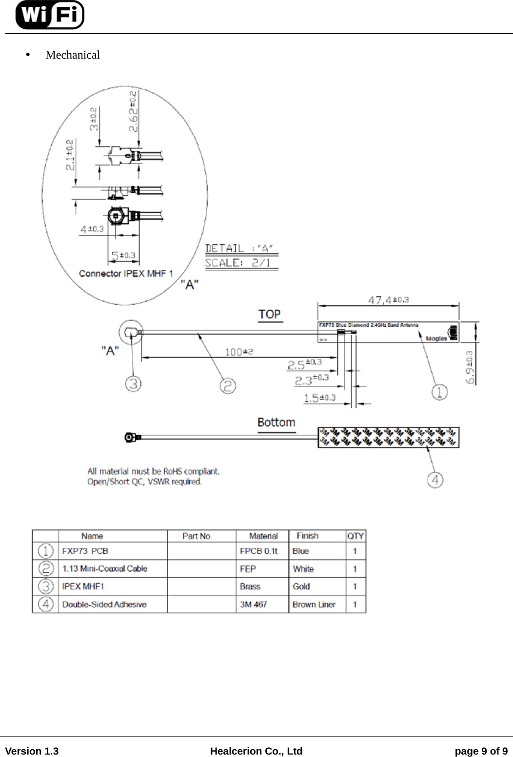
Healcerion SWM300 WiFi module User Manual

Healcerion Co.,Ltd WiFi module Users Manual

Users Manual

                                                                                                                                       Version 1.3  Healcerion Co., Ltd  page 1 of 9   Manual for SWM-300 Wi-Fi module  1. Introduction SWM-300 is a Wi-Fi module compliant with 802.11 g/n(20,40MHz) MAC/baseband/radio optimized for low-power applications. The core chipset is from Taiyo-Yuden, part number WYSBMVGX4 and Antenna is FXP73.07.0100A Blue Diamond 2.4GHz Band made by Taoglas.  2. Hardware Architecture:  2.1 Main Module / Chipset Information  Main Module : WYSBMVGX4, Taiyo-Yuden, IEEE802.11 g/n Wireless LAN Module  Core Chipset : 88W8787, Marvell , WLAN/FM Single-Chip SoC  Antenna : FXP73.07.0100A, Taoglas , FXP73 Blue Diamond 2.4GHz Band Antenna  2.2 Circuit Block Diagram The major internal and external block diagram of SWM-300 is illustrated in Figure 1.   Figure 1. SWM-300 block diagram and System Interface
                                                                                                                                       Version 1.3  Healcerion Co., Ltd  page 2 of 9    The major internal and external block diagram of WYSBMVGX4 is illustrated in Figure 2.   Figure 2. WYSBMVGX4 block diagram and System Interface
                                                                                                                                       Version 1.3  Healcerion Co., Ltd  page 3 of 9    3. Operational Description  WYSBMVGX4 is the 802.11 g/n(20,40MHz) RF Module that acts as a communication controller for users of a wireless device to connect to Mobile Device e.g. Smartphone, Tablet, etc. This uses  802.11 g/n(20MHz) network with 11 channels,802.11 n(40MHz) network with 9 channels at 2.4GHz   - Features • Low power dissipation • CMOS and low-swing sine wave input clock • 12, 13, 19.2, 24, 26, 38.4, and 52 MHz crystal clock support with auto-frequency detection using external 32.768 KHz CMOS-level sleep clock • Sleep and standby modes for low power operation • Fully compatible with Marvell Power Management device(s) • 802.11 g/n(20,40MHz) compliant, with maximum data rates up to 72 Mbps (20 MHz channel) and 150 Mbps (40 MHz channel) • 802.11g/n 1x1 SISO with on-chip Marvell SISO RF radio • PHY data rates up to 150 Mbps  - Time base of the RF frequency • For IF and RF frequency, a crystal(40MHz) is a clock reference.  - Synthesizer • Synthesizer inside Transceiver. Internal voltage controlled oscillator (VCO) provides the desired LO signal base on the phase-locked loop (PLL) with a relatively wide tuning range for this application.  - Transmission • Base-band Processing (BBP) IC has DSSS (BPSK/QPSK/CCK) and OFDM (BPSK/QPSK/16QAM/64QAM) modulation function, it provides transmission data rate are 1, 2, 5.5, 11Mbps on DSSS and 6, 12, 18, 24, 36, 48, 54 Mbps on OFDM. Digital data signal will be converted to analog (TX IQ) signals through DAC in BBP IC, TX IQ pass through to low pass filter. TX I/Q signal use direct conversion (zero-IF) architecture converter to generate carrier frequency signal. Transceiver IC and internal PA magnify output power.  - Receiver • Reverse direction isolation of LNA inside Transceiver IC suppresses unwanted radiation. Then RF signal will be directly down to IF signal (RX IQ) and high frequency spurious emissions are suppressed by LPF. At last RX IQ signal will be demodulated digital data.  - Power Control Level • It uses open-loop power control function to limit RF output power level using a calibration file.
                                                                                                                                       Version 1.3  Healcerion Co., Ltd  page 4 of 9     - Integrated Network Processor • Network processor manages Wi-Fi link operations. The network processor code is loaded automatically from a ROM. The network processor is optimized for energy efficient communications   - Product Details  • Data Modulation OFDM (BPSK / QPSK / 16QAM / 64QAM) • Frequency Range 2412-2462 MHz  ( 20MHz)                                 2422-2452 MHz  (40MHz)  - Permitted Output Power  • 9.45dBm ± 0.50dB  - Voltage Specifications • Absolute maximum ratings  Item Symbol  Rating  Remark Min. Typ. Max.  Unit Supply Voltage 1  VIO  -    4.0  V   Supply Voltage 2  VDD18  -    1.98  V   Supply Voltage 3  VBAT  -    5.6  V   Storage temperature range  Tstg  -30    100  Degree C   Operation temperature range  Topr  -20  25  70  Degree C    • Recommended operating range  Item Symbol  Rating  Remark Min. Typ. Max. Unit Supply Voltage 1  VIO  1.62/2.97 1.8/3.3 1.98/3.63 V   Supply Voltage 2  VDD18  1.71  1.8  1.89  V   Supply Voltage 3  VBAT 3.2 3.3 4.3  V
                                                                                                                                       Version 1.3  Healcerion Co., Ltd  page 5 of 9    4. Notice  This device complies with Part 15 of FCC Rules. Operation is Subject to following two conditions: (1) This device may not cause harmful interference, and (2) This device must accept any interference received including interference that cause undesired operation.  This equipment has been tested and found to comply within the limits for a Class B digital device,  pursuant to part 15 of the FCC Rules. These limits are designed to provide reasonable protection against harmful interference in a residential installation.  This equipment generates, uses, and can radiate radio frequency energy and, if not installed and used in accordance with the instructions, may cause harmful interference to radio communications. However, there is no guarantee that interference will not occur in a particular installation. If this equipment does cause harmful interference to radio or television reception, which can be determined by turning the equipment off and on, the user is encouraged to try to correct the interference by one or more of the following measures:  • Reorient or relocate the receiving antenna  • Increase the separation between the equipment and receiver  • Connect the equipment into an outlet on a different circuit from that to which the receiver is connected  • Consult the dealer or an experienced radio/TV technician for help.  For product available in the USA/Canada market, only channel 1~11 can be operated. Selection of other channels is not possible  IMPORTANT NOTE: FCC Radiation Exposure Statement: This equipment complies with FCC radiation exposure limits set forth for an uncontrolled environment. This device and its antenna(s) must not be co-located or operation in conjunction with any other antenna or transmitter. Any changes or modifications not expressly approved by the manufacturer could void the user's authority to operate this equipment.   USERS MANUAL OF THE END PRODUCT: The end user has to be informed that the FCC radio-frequency exposure guidelines for an uncontrolled environment can be satisfied. The end user has to also be informed that any changes or modifications not expressly approved by the manufacturer could void the user's authority to operate this equipment. If the size of the end product is smaller than 8x10cm, then additional FCC part 15.19 statement is required to be available in the users manual: This device complies with Part 15 of FCC rules. Operation is subject to the following two conditions: (1) this device may not cause harmful interference and (2) this device must accept any interference received, including interference that may cause undesired operation.  LABEL OF THE END PRODUCT: The final end product must be labeled in a visible area with the following " Contains  FCC ID: 2ADXV-SWM300". If the size of the end product is larger than 8x10cm, then the following FCC part 15.19 statement has to also be available on the label:  This device complies with Part 15 of FCC rules. Operation is subject to the following two conditions: (1) this device may not cause harmful interference and (2) this device must accept any interference received, including interference that may cause undesired operation.
                                                                                                                                       Version 1.3  Healcerion Co., Ltd  page 6 of 9    5. Installation This SWM-300 module must be installed in a device and not allow the user to replace nor modify it. The final end product must be labeled in a visible area with the following " Contains FCC ID: 2ADXVSWM300".   It is suggested that module is placed in the following areas of the user's board as far as possible, to reduce the influence of the antenna and wireless signal. and at the same time, please consult someone technical support staff to assist the placement of modules and related areas of layout design          Note : Please note that the SWM-300 is supplied without any shield casing, all the components are exposed. Therefore, must be taken for ESD (electrostatic discharge), electromagnetic environment
                                                                                                                                       Version 1.3  Healcerion Co., Ltd  page 7 of 9    5.1 PIN Description    6. Antenna Description   Part Nomber : FXP73.07.0100A  Overview The FXP73 Blue Diamond 2.4GHz Antenna works on WiFi, ZigBee, Bluetooth and ISM band at 2.4 GHz. This antenna has been designed with a specific solution to cover the current market applications that require rectangular form-factor, with easy installation through a cable connection.  Feature  2.5dBi Gain  IPEX MHFI Connector (U.FL compatible)  100 mm Cable  47*7*0.1 mm  Characteristics
                                                                                                                                       Version 1.3  Healcerion Co., Ltd  page 8 of 9
                                                                                                                                       Version 1.3  Healcerion Co., Ltd  page 9 of 9     Mechanical

Navigation menu