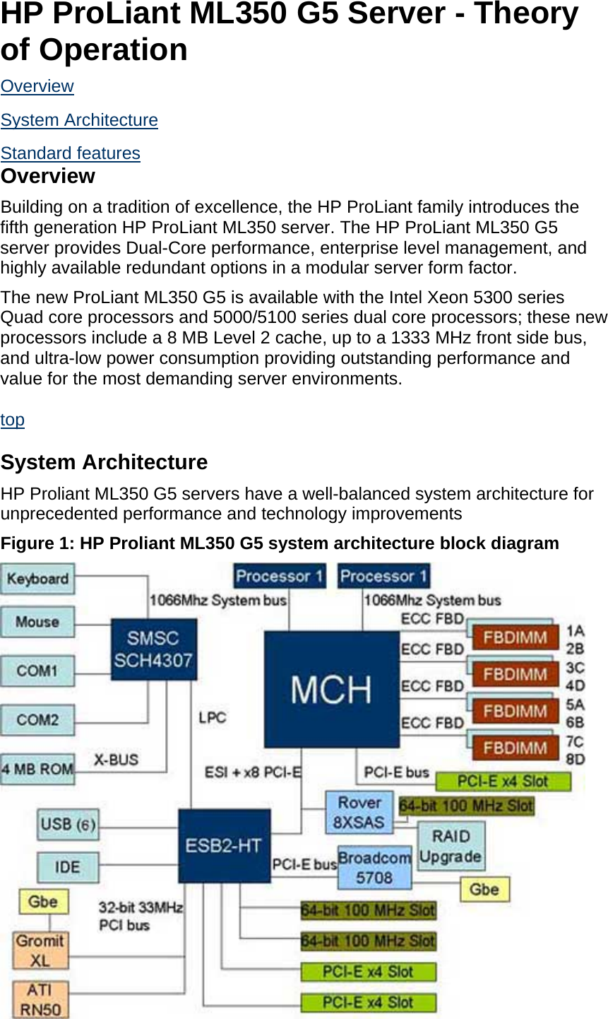
Hewlett Packard ML350G COMPUTER SERVER User Manual HP ProLiant ML350 G5 Server Theory of Operation

Hewlett-Packard (Thailand) Ltd. COMPUTER SERVER HP ProLiant ML350 G5 Server Theory of Operation

USERS MANUAL

HP ProLiant ML350 G5 Server - Theory of Operation Overview  System Architecture  Standard features  Overview Building on a tradition of excellence, the HP ProLiant family introduces the fifth generation HP ProLiant ML350 server. The HP ProLiant ML350 G5 server provides Dual-Core performance, enterprise level management, and highly available redundant options in a modular server form factor. The new ProLiant ML350 G5 is available with the Intel Xeon 5300 series Quad core processors and 5000/5100 series dual core processors; these new processors include a 8 MB Level 2 cache, up to a 1333 MHz front side bus, and ultra-low power consumption providing outstanding performance and value for the most demanding server environments.  top  System Architecture HP Proliant ML350 G5 servers have a well-balanced system architecture for unprecedented performance and technology improvements Figure 1: HP Proliant ML350 G5 system architecture block diagram
  MCH - Memory Controller Hub. It is the system bus arbortration controller.    ESB2 - Enterprise South Bridge #2. ESB2 is the System I/O controller.  top  Standard features  Processors:    Dual-Core and Quad-Core Intel Xeon 5000 sequence processors with up to 8 MB Level 2 cache for blazing performance; systems support up to 2 processors    1333/1066/667 MHz front side bus (FSB).    Intel 5000Z chipset.   Memory:    Eight PC2-5300 FB-DIMMs (DDR2 667) sockets with Online-Spare support for cost-effective memory configuration and expansion.    Up to 16 GB of memory, supported by (8) slots of PC2-5300 Fully Buffered DIMMs (DDR2-667); 4:1 interleaving; and online spare    Up to 32 GB of memory supported on Quad-Core (5300 series) models  NOTE: Memory DIMMs in systems with the Front Side Bus (FSB) running at 1333 MHz will run at 667 MHz and in systems with a FSB running at 1066 MHz or 667 MHz the memory DIMMs will run at 533 MHz.  Storage Controllers:    Entry Models: Smart Array E200i Controller (integrated SAS/SATA Hot-Plug Controller with RAID 0/1 support).    Base Modes: Smart Array E200i Controller with 128 MB BBWC included.    128 MB BBWC optional upgrade kit for RAID 5 support also available.   Internal Drive Support:    Up to eight SFF (2.5") or six LFF (3.5") Hot Plug Serial Attached SCSI (SAS) or Serial-ATA (SATA) hard drives.    Maximum of 4.50 TB of internal storage capacity (using Hot-Plug SATA drives).   Network Controller:    Embedded NC373i Multifunction Gigabit Network Adapter with TCP/IP Offload Engine, including support for Accelerated iSCSI through an optional ProLiant Essentials Licensing Kit.   Expansion Slots:    Six total expansion slots.    One 64-bit/133 MHz PCI-X; two 64-bit/100 MHz PCI-X; three x8 PCI Express (x4 speed).    Optional PCI-X Expander provides additional two 64-bit/100 MHz PCI-X slots by converting a single PCI Express slot   USB Ports:    Six USB 2.0 ports: (2) front; (2) rear; (2) internal.   Redundancy:    Optional Hot plug redundant power supplies.    Support for optional redundant system fans.   Management:    Integrated Lights-Out 2 (iLO 2) standard for remote management.    Support for ROM-Based Setup Utility (RBSU) and redundant ROM.    Systems Insight Manager, SmartStart, and Automatic Server Recovery 2 (ASR-2).    HP Power Meter and Power Regulator for ProLiant, delivering integrated power consumption monitoring and server level, policy based power management for industry leading energy efficiency and savings on system power and cooling costs.
 Deployment/Serviceability:    Optional parallel and second serial port available without using a PCI slot.    Tool-free chassis entry and component access.    Tool-free motherboard removal.    Universal rail solution supporting both square and round hole rack environments.   Warranty:    Protected by HP Services and a worldwide network of resellers and service providers. Three-year Next Business Day, onsite limited global warranty. Certain restrictions and exclusions apply. Pre-Failure Notification on processors, memory, and SAS hard drives. SATA hard drives have a one-year warranty.  top  HP ProLiant ML350 G5 Server - System Views Front View  Rear View  Internal View  Front View Figure 1: ML350 G5 Server - Front View  Figure 2: Front Panel Components
 Item  Description 1  Removable media bays (4) 2  CD-ROM drive 3  Floppy disk drive (optional) 4  Hot-plug hard drive bays 5  USB connectors (2) Figure 3: Front panel LEDs and buttons
 Item  Description  Status 1  System power LED    Green = Power on    Amber = System shut down, but power still applied    Off = No power  2  External health LED (power supply)   Green = Normal    Amber = Power redundancy failure    Red = Critical power supply failure  3  NIC 1 activity LED   Green = Network link    Flashing = Network link and activity    Off = No link to network. If power is off, view status on the rear panel RJ-45 LEDs  4  NIC 2/iLO activity LED   Green = Network link    Flashing = Network link and activity    Off = No link to network. If power is off, view status on the rear panel RJ-45 LEDs  5  UID LED    Blue = Activated    Flashing = System remotely managed    Off = Deactivated  6  UID button  - 7  Internal health LED   Green = Normal    Amber = System degraded.    Red = System critical.    Off = Normal (when in standby mode)  8  Power On/Standby button  - top
Rear View Figure 4: Rear View  Item  Description 1  Video connector 2  Serial connector 3  USB connectors (2) 4  RJ-45 Ethernet connector (iLO 2 management) 5  RJ-45 Ethernet connector (data) 6  PCI Express x8 slots (x4 routed) 7  PCI-X slots (100 MHz) 8  PCI-X slot (133 MHz) 9  Optional redundant hot-plug power supply bay 10  Mouse connector 11  Keyboard connector
Item  Description 12  Power cord connector Figure 5: Rear panel LEDs and buttons  Item  Description  Status 1  UID LED and button    Blue = Activated    Flashing blue = Remote inquiry    Off = Deactivated  2  iLO 2/data activity LED    Green or flashing = Network activity    Off = No network activity  3  iLO 2/data link LED    Green = Linked to network    Off = Not linked to network  4  10/100/1000 NIC activity LED    Green or flashing = Network activity    Off = No network activity  5  10/100/1000 NIC link LED    Green = Linked to network    Off = Not linked to network  top  Internal View Figure 6: Internal View
 Item  Description 1  Up to 2 Intel dual-core Xeon 5000 series processors with 4 MB of cache 2  5 Media bays 3  Support for 8 SFF or 6 LFF SAS and SATA hard drives 4  Eight PC2-5300F slots for up to 32 GB 667 MHz FB-DIMM Memory 5  3 64-bit PCI-X slots 6  3 PCI Express slots 7  Dual redundant fan option  Figure 7: SAS/SATA Hard Drive
 1 - SAS/SATA Hard Drive  2 - Fault/UID LED (amber/blue)  3 - Online LED (green)  Figure 8: SAS/SATA Hard Drive Blank  1 - SAS/SATA hard disk drive  Figure 9: SAS/SATA backplane
 1 - SAS/SATA cable connector (drives 5-8)  2 - SAS/SATA cable connector (drives 1-4)  3 - SAS/SATA backplane  Figure 10: Battery-backed write cache option  1 - Smart array battery-backed write cache (64 MB - RAID 0,1; 128 MB - RAID 5)  2 - SAS/SATA cable connector (drives 1-4)  3 - SAS/SATA cable connector (drives 5-8)  Figure 11: Diskette Drive
 1 - Diskette Drive  Figure 12: Optical device  1 - Optical device  Figure 13: Media device blank
 1 - Media device blank  Figure 14: Media retention bracket  1 - Media retention bracket  Figure 15: System memory
 Item  Description 1  Slot 1, Bank A 2  Slot 2, Bank B 3  Slot 3, Bank C 4  Slot 4, Bank D 5  Slot 5, Bank A 6  Slot 6, Bank B 7  Slot 7, Bank C 8  Slot 8, Bank D 9  Standard DIMM module Figure 16: Fan and DIMM baffle
 1 - Fans  2 - DIMM baffle  Figure 17: Processor and heat sink  1 - Processor  2 - Processor blank  3 - PPM  4 - Heat sink  Figure 18: Expansion board options
 1 - Full-length PCI expansion slot retention clips  2 - PCI Express x3 slots  3 - PCI-X slots 2-3 (100 MHz)  4 - PCI-X slots 1 (133 MHz)  Figure 19: Parallel/second serial connector option  1 - Parallel connector option  2 - Second serial connector option  Figure 20: Power supply
 1 - Power supply 1  2 - Power supply 2 (redundant)  3 - Power supply  Figure 21: System board  Item  Description 1  Processor socket 0 2  Processor socket 1 3  IDE connector 4  Diskette drive connector 5  System battery
Item  Description 6  System maintenance switch 7  Processor power module top   NOTE:  THE MANUFACTURER IS NOT RESPONSIBLE FOR ANY RADIO OR TV INTERFERENCE CAUSED BY UNAUTHORIZED MODIFICATIONS COULD VOID THE USER’S AUTHORITY TO OPERATE THE EQUIPMENT  FCC GUIDELINES  WARNING:  This equipment has been tested and found to comply with the limits for a Class B digital device, pursuant to part 15 of the FCC rules.  These limits are designed to provide reasonable protection against harmful interference in a residential installation.  The equipment generates uses and can radiate radio frequency energy and, can radiate radio frequency energy and, if not installed and used in accordance with the instructions, may cause harmful interference will not occur in a particular installation.  If this equipment does cause harmful interference to radio or television reception, which can be determined by turning the equipment off and on, the use is encouraged to try to correct the interference by one or more of the following measures: -  Reorient or relocate the receiving antenna. -  Increase the separation between the equipment and receiver. -  Connect the equipment into an outlet on a circuit different from that to which the receiver is connected. -  Consult the dealer or an experienced radio/TV technician for help

Navigation menu