Hi G Tek IGAV243916 AVL READER User Manual TTMS installation guide 1 2
Hi-G-Tek Ltd AVL READER TTMS installation guide 1 2
UserManual.wiki
>
Hi G Tek
>
IGAV243916 User Manual
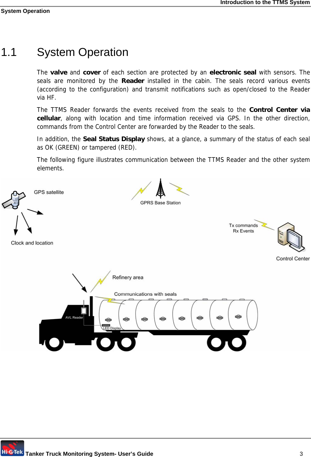
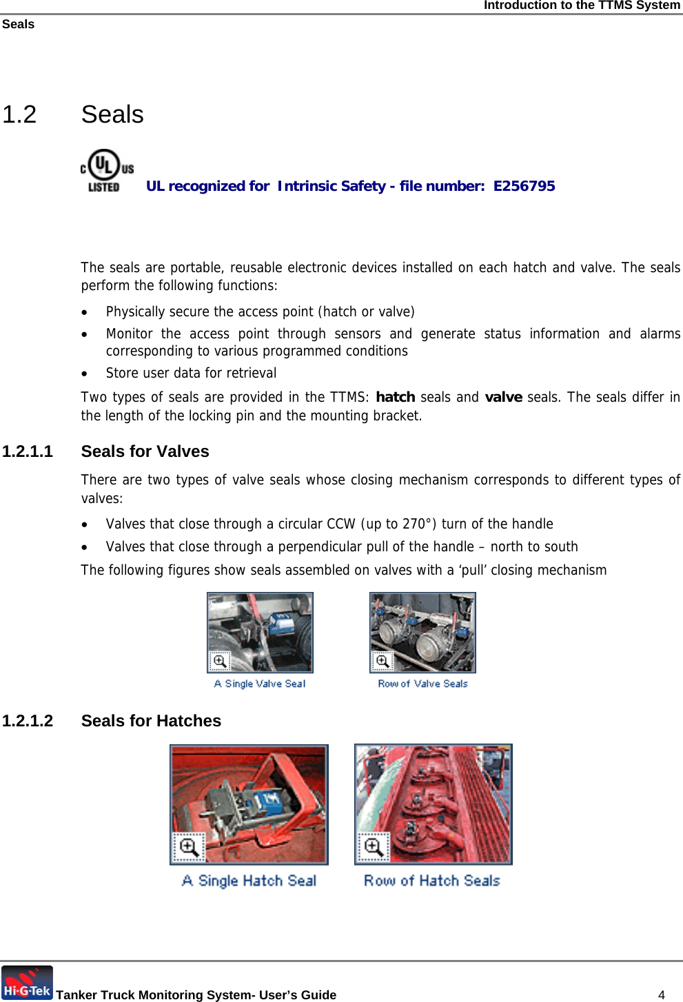
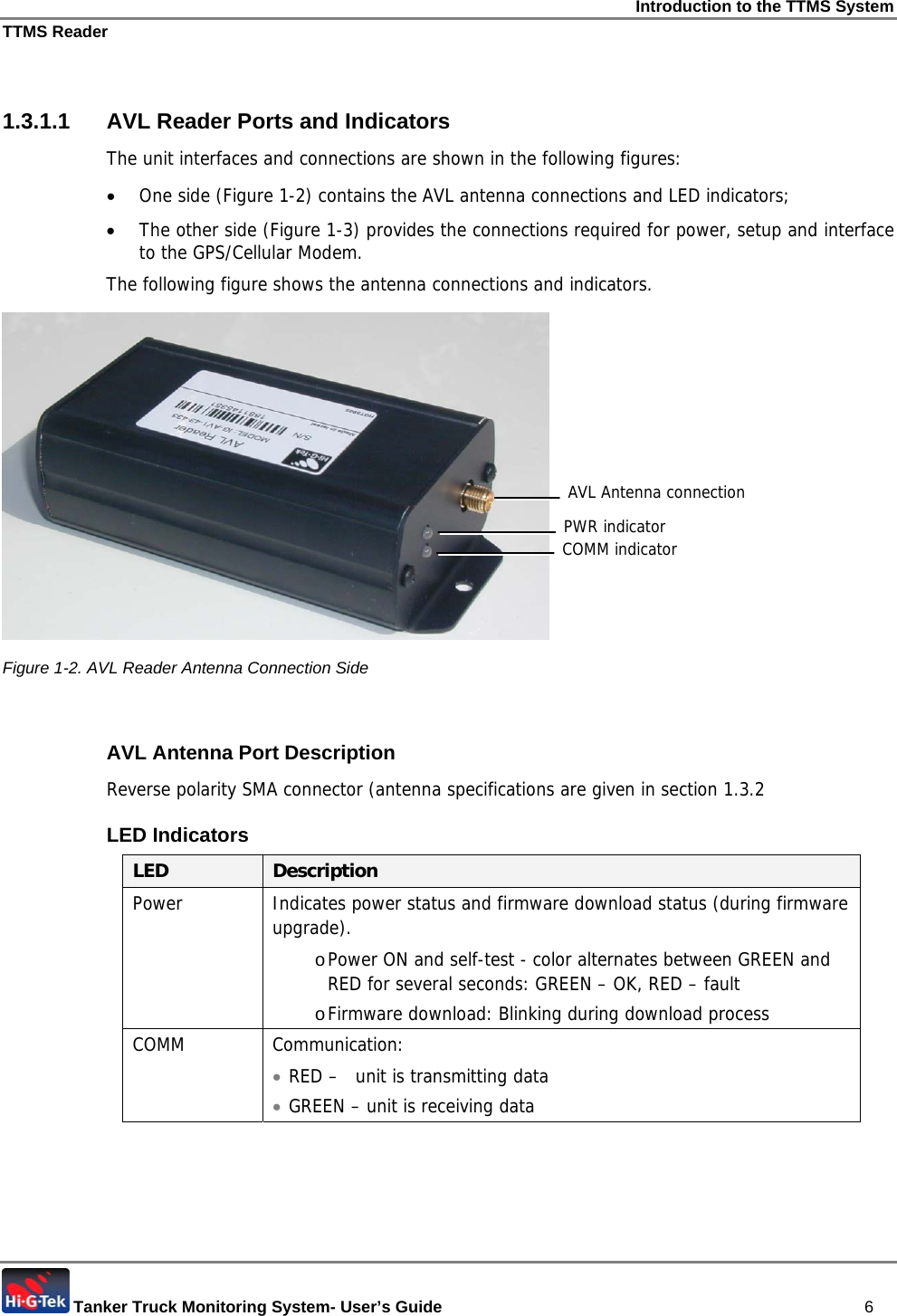
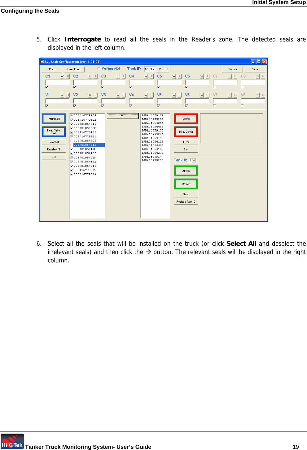
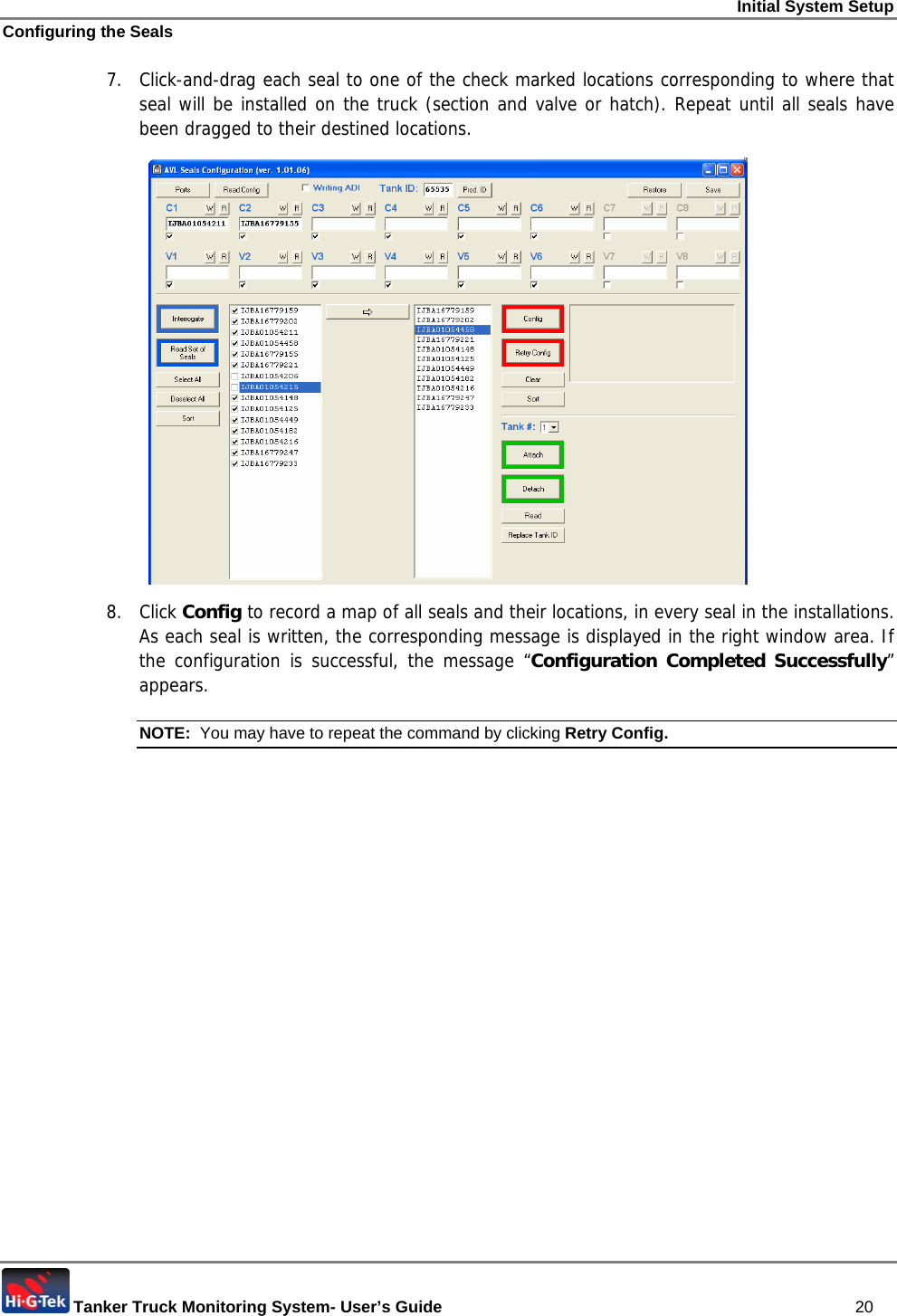
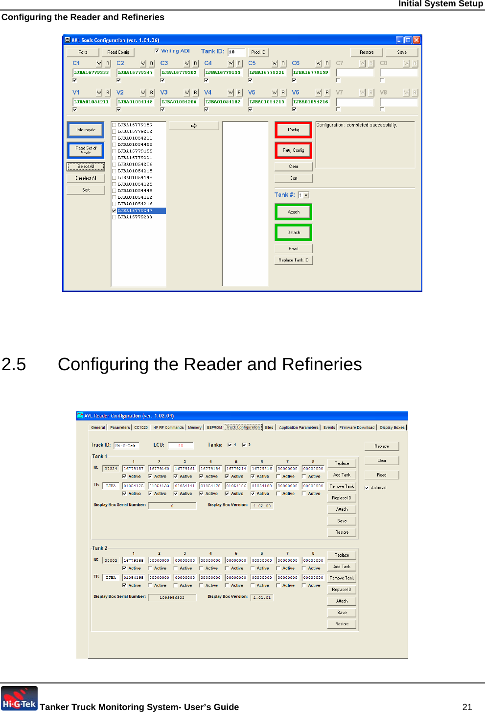
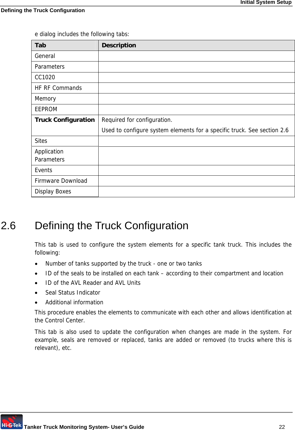
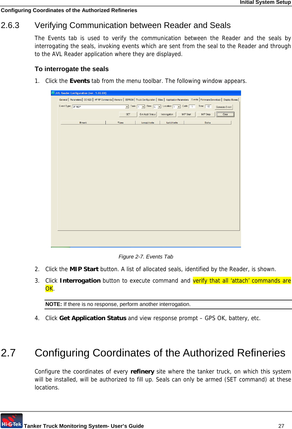
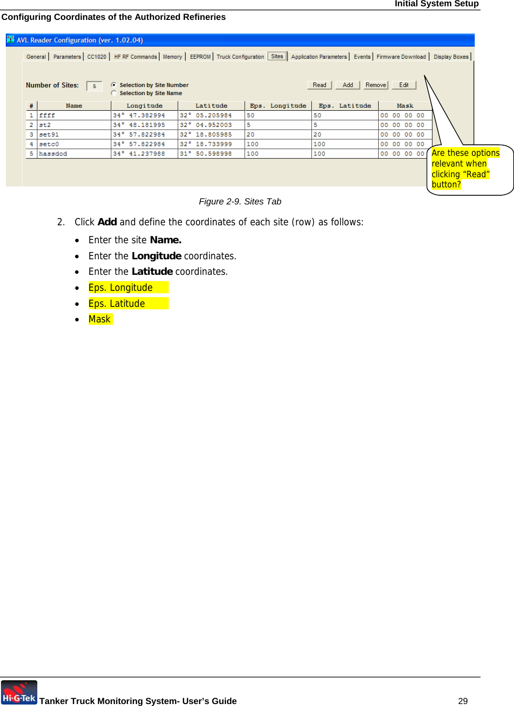
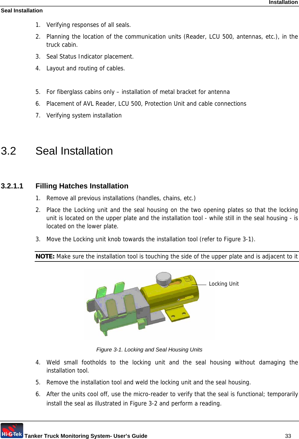
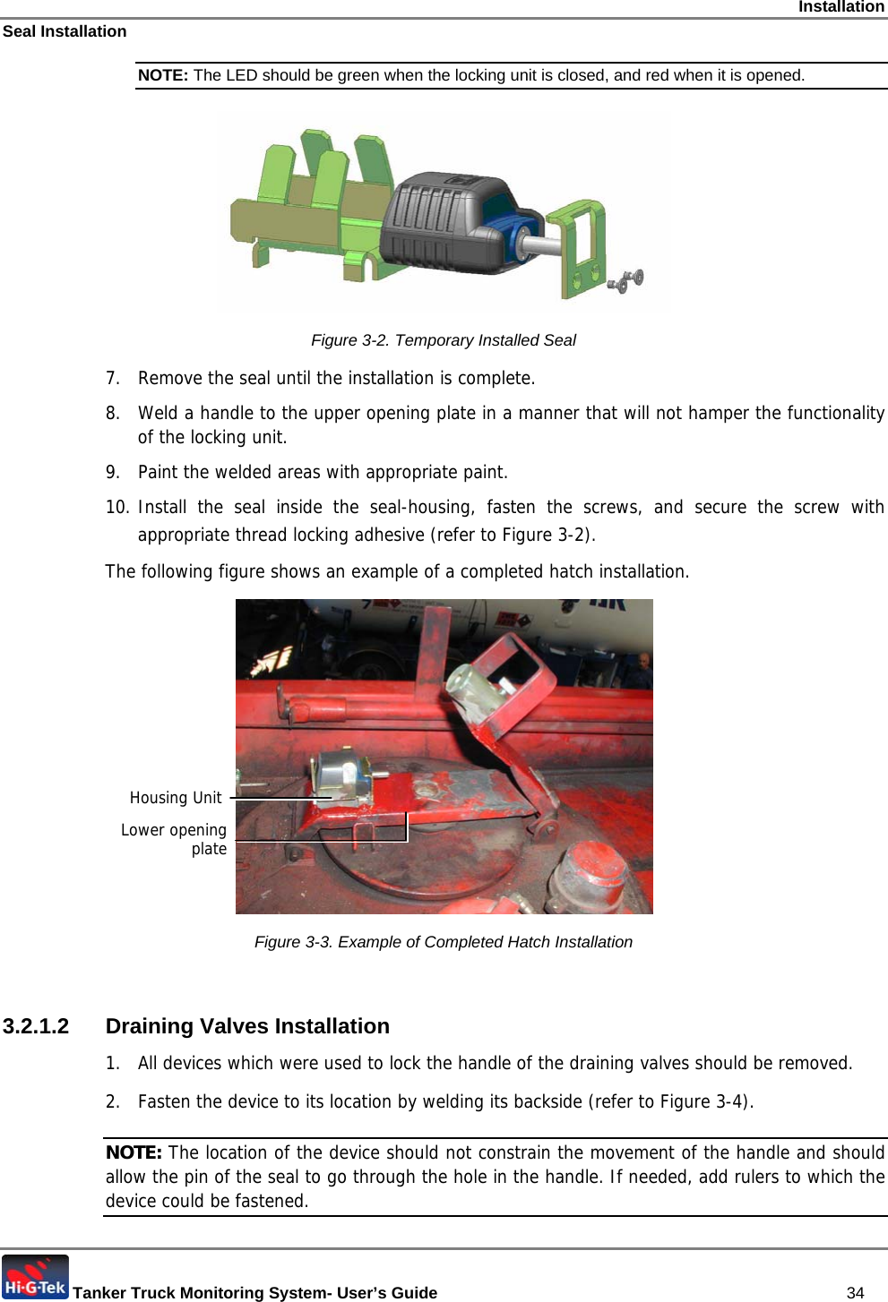
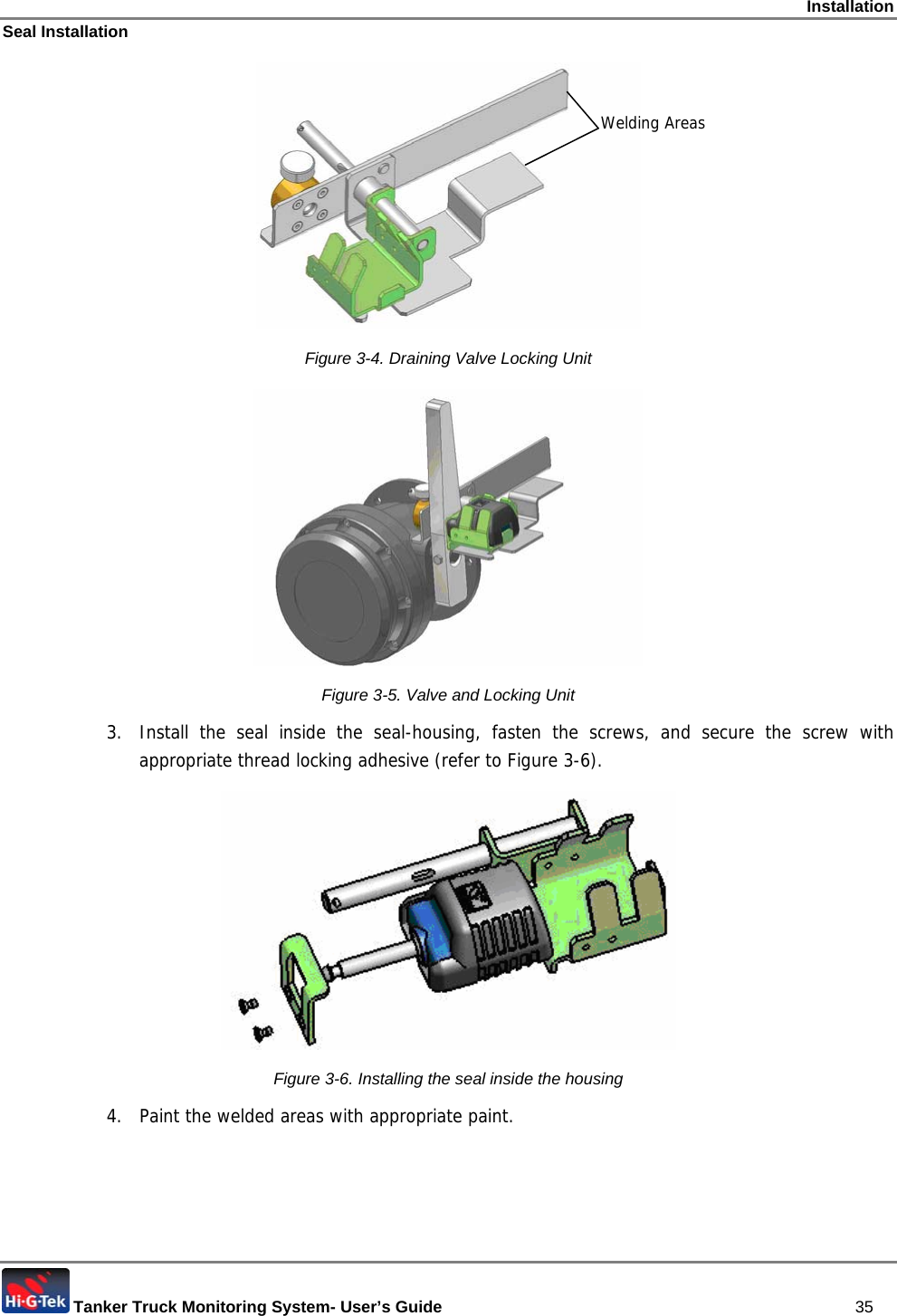
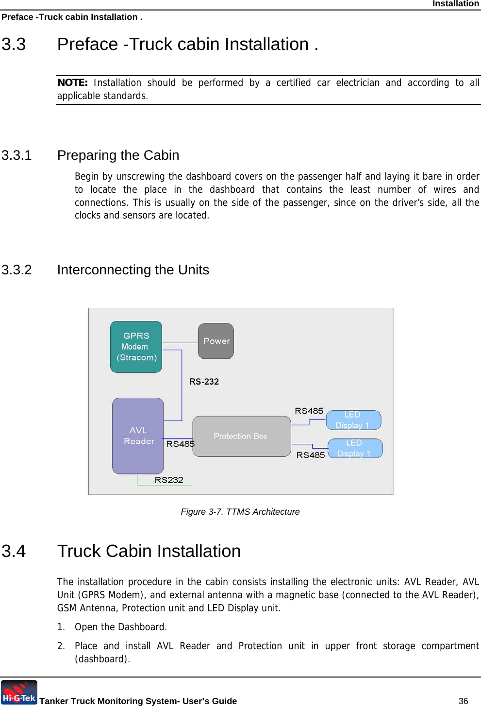
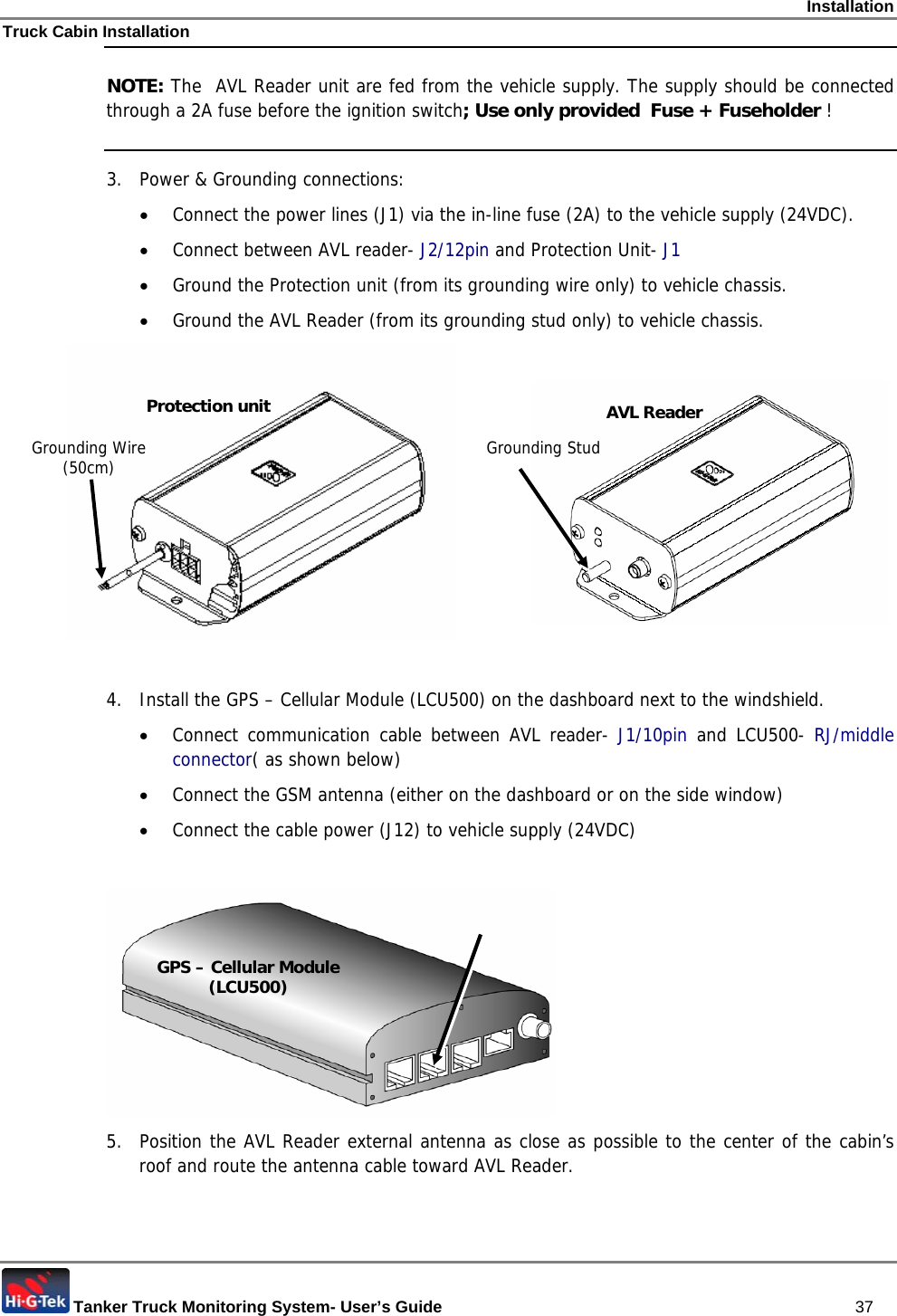
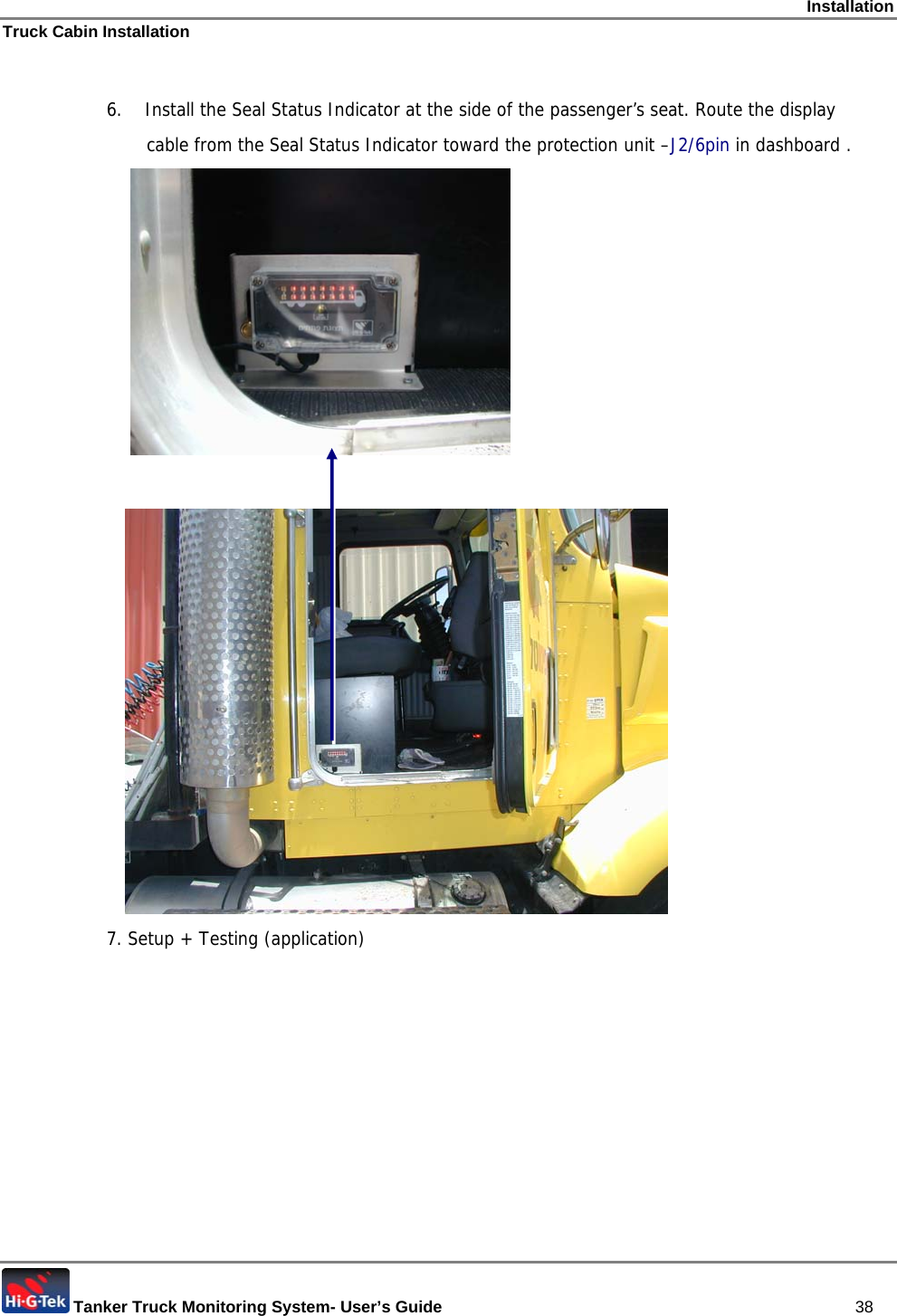
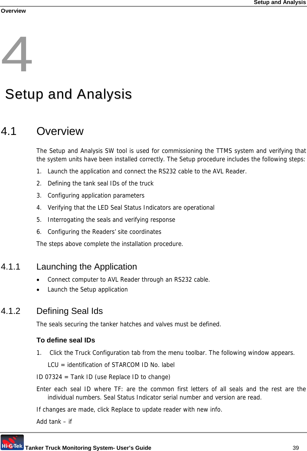
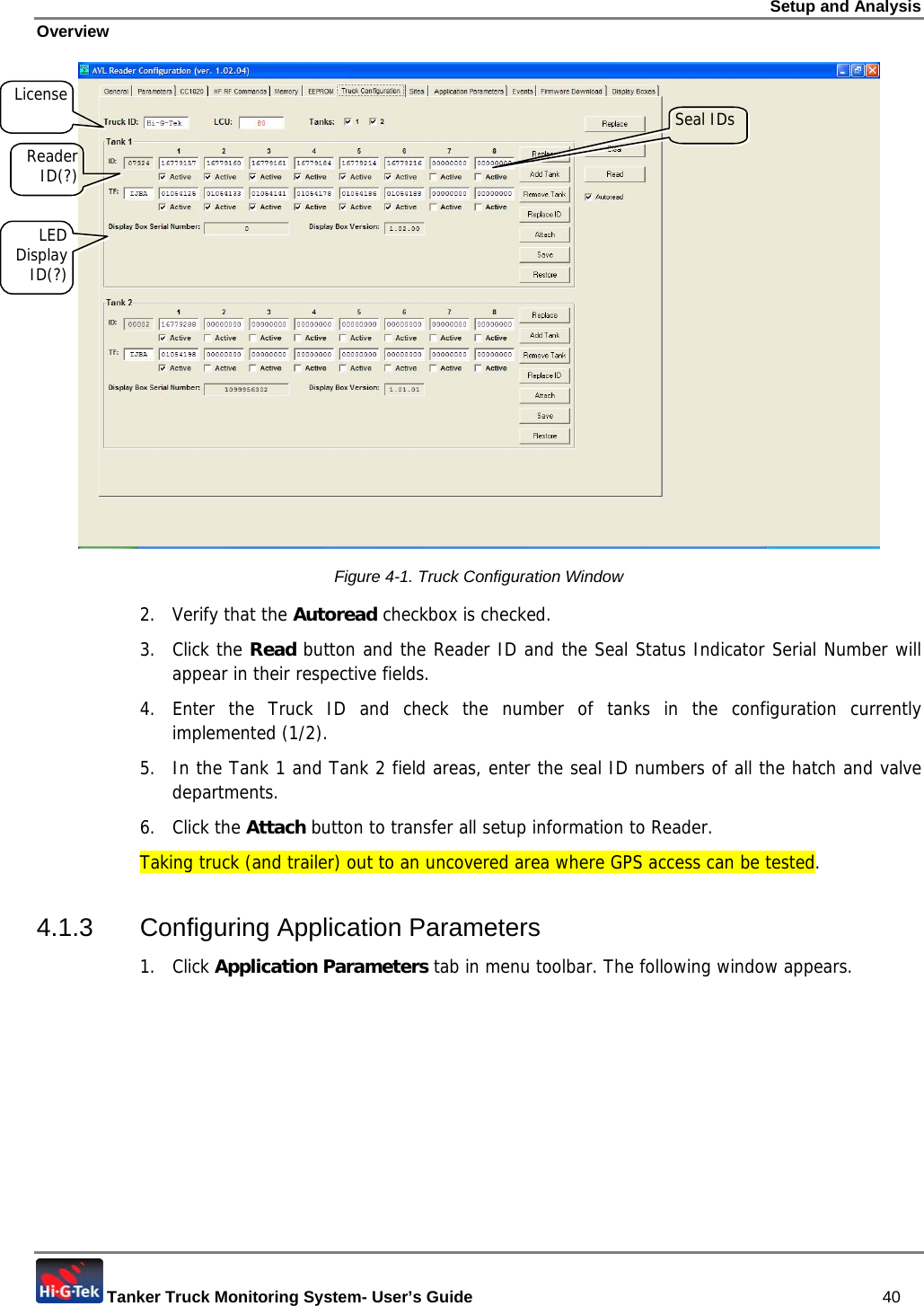
USERS MANUAL
Navigation menu
Upload a User Manual
Namespaces
Wiki Guide
HTML
PDF
Info
Views
User Manual
Discussion / Help
Navigation