Hi G Tek IGRS46D9916 Data Reader User Manual UM4710 rev A6
Hi-G-Tek Ltd Data Reader UM4710 rev A6
UserManual.wiki
>
Hi G Tek
>
IGRS46D9916 User Manual
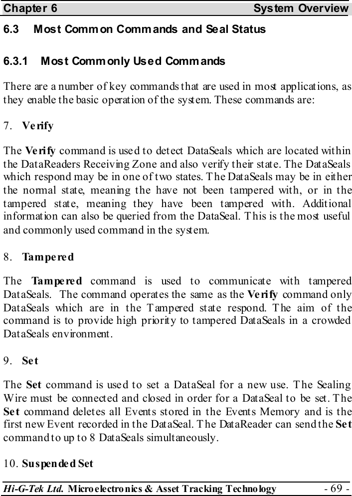
Manual revised
Navigation menu
Upload a User Manual
Namespaces
Wiki Guide
HTML
PDF
Info
Views
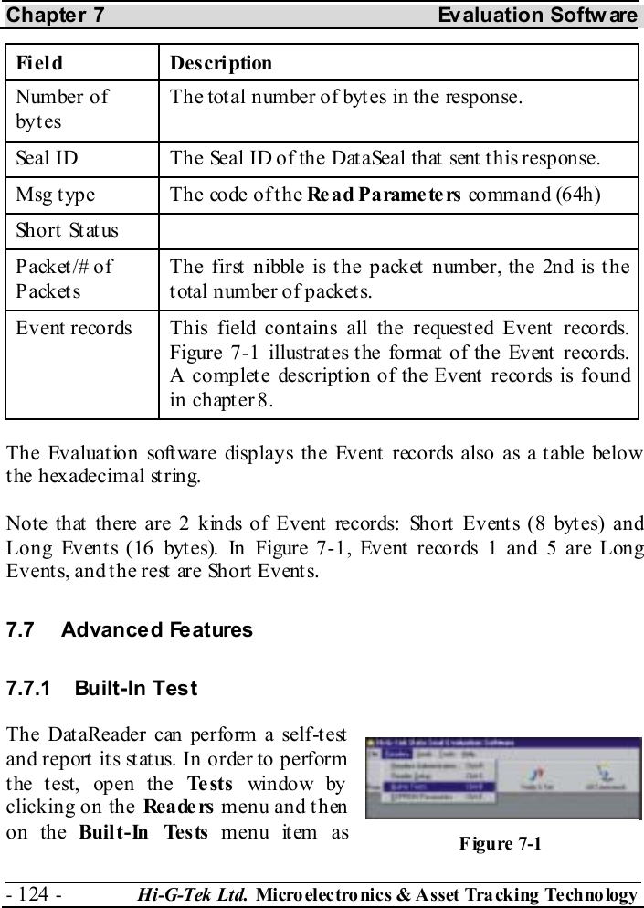
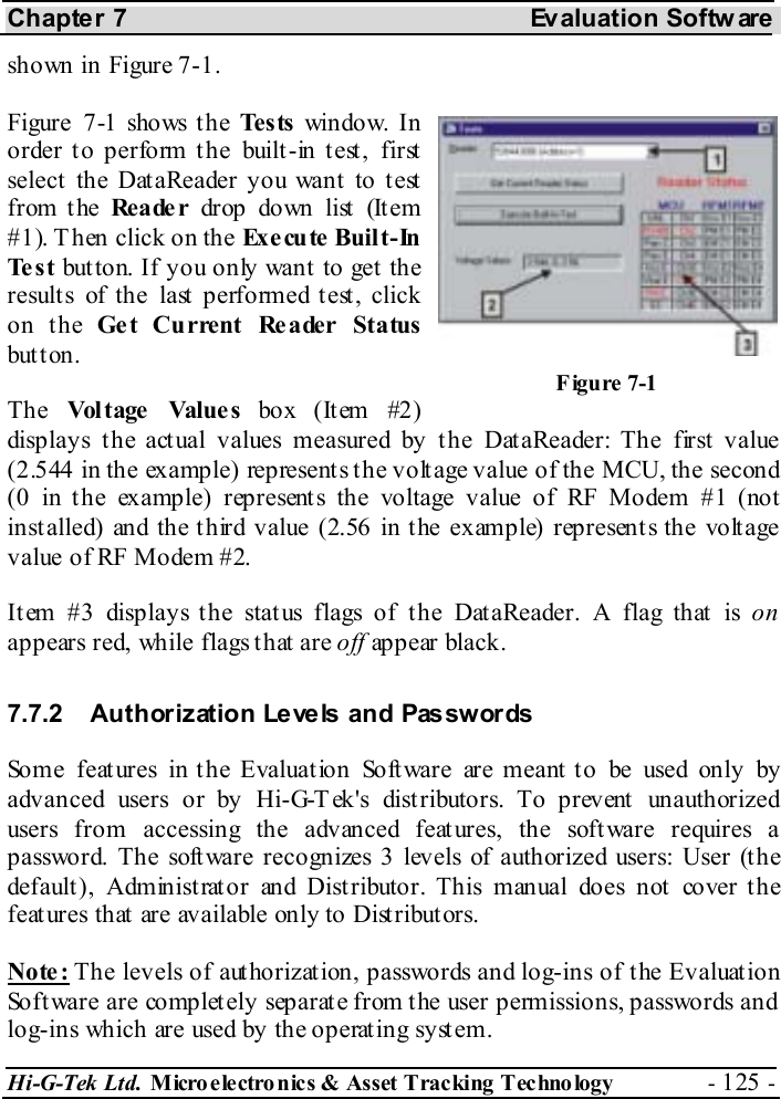
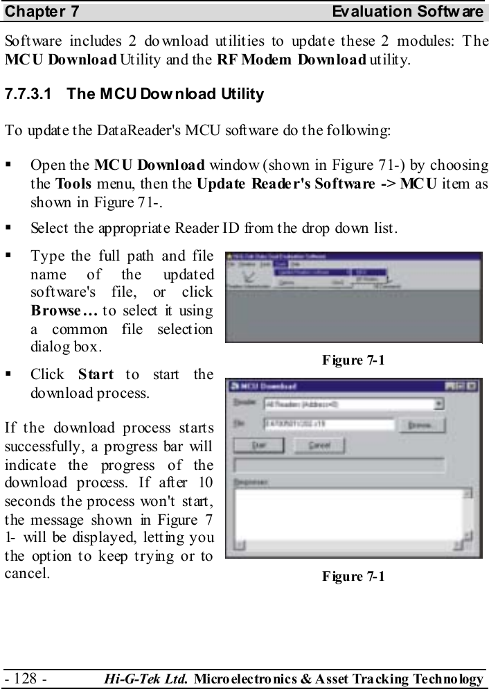
User Manual
Discussion / Help
Navigation

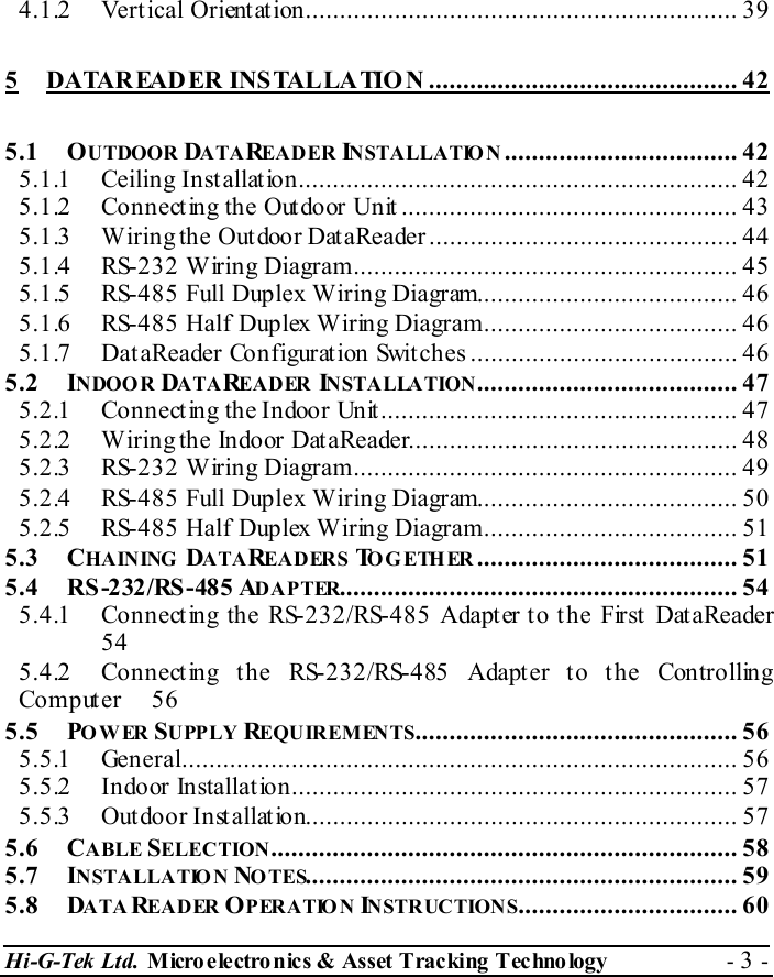


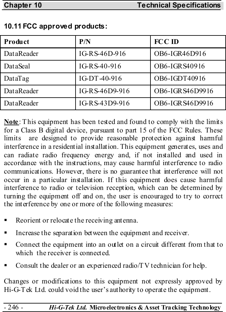
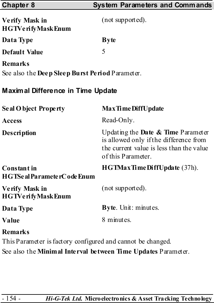
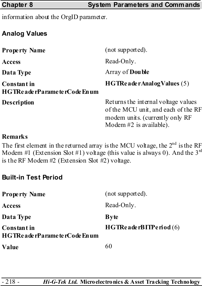
![Chapter 5 DataReader Installation and Operating Instructions Hi-G-Tek Ltd. Micro electro nics & Asset Tracking Technology - 57 - Example: 10 DataReaders connected in a daisy chain require 10x1.7=17W of power supply. Note that if the power supply is installed in a high temperature area (usually above 40° C), there is a derate in power supply wattage. (Refer to your power supply manual). For safety reasons, power supply current should be limited to 3A. Current limitation should be done internally in the power supply, or externally with a 3A fuse. Both in t he Out door and Indoor syst ems, t he power supply should be installed indoor. When power supply cable ends are connected directly to system cable, a proper isolat ion should be made. Using heat shrink t ube is recommended. 5.5.2 Indoor Installation When the DataReader is installed indoor, the power supply used should be UL1950 approved. A desktop style with IEC320 inlet is recommended. 5.5.3 Outdoor Installation For safety reasons, the DataReader shall be used with the following power supply only: HI-G-TEK P/N Manufactu re r Manu factu re r P/N Supply Voltage [V] Supply Wattage [W] HGT5291A EDAC EA1050D-240 24 24](https://usermanual.wiki/Hi-G-Tek/IGRS46D9916/User-Guide-398653-Page-57.png)


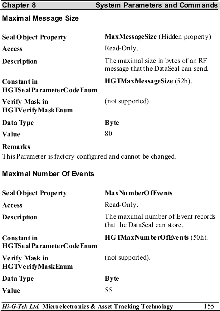
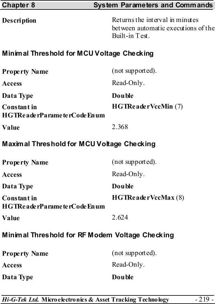


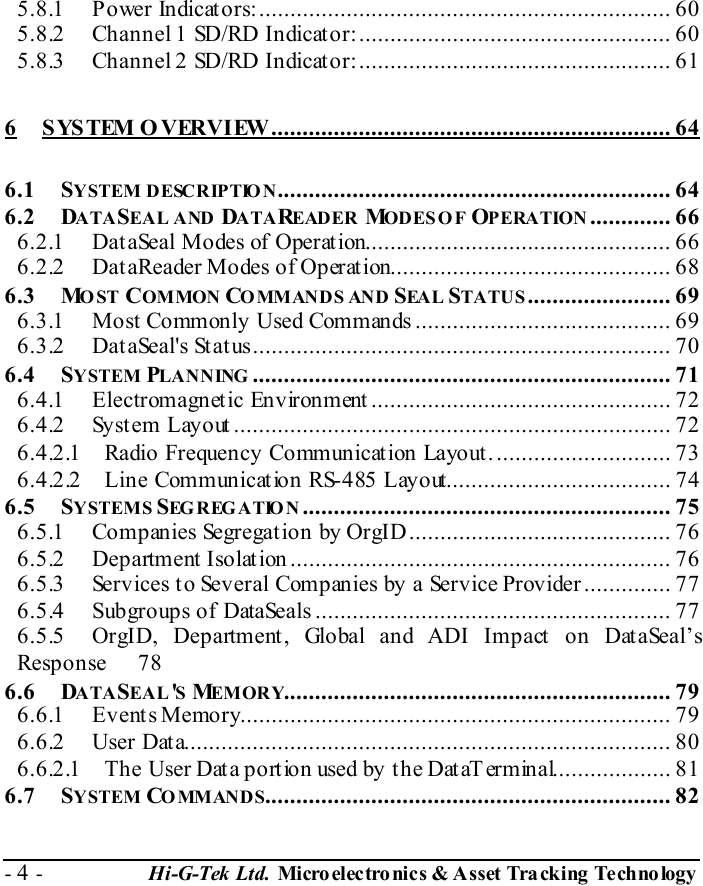
![Chapter 10 Technical Specifications - 238 - Hi-G-Tek Ltd. Micro elec tro nics & A sset Tra cking Techno logy 10 Technical Specifications 10.1 RS485 24V Outdoor DataReader 24V Outdoor DataReader IG-RS-46D-916 IG-RS-46D-433 IG-RS-46D-318 IG-RS-46D-315 Physical Characteristics Dimensions 195x165x95mm, not including antenna Weight 1000gr Power requirements – External Nominal - 24VDC Mini mum – 10VDC Maximum – 35VDC Power Consumption 1.7W @Tx, 1.1W@Rx Performance Characteristics Interface RS485 optically isolated Operating frequency [MHz] 916.5 433.92 318 315 Read Range 30m @ open space Environmental Conditions Operating Temperature -40ºC — 70ºC Storage Temperature -40ºC — 70ºC Humidity 90% Non condensing Mechanical Vibration As per MIL-810D & SAE J1455 Mechanical Shock As per MIL-810D & SAE J1455 Standards Designed according to FCC part15C UL1950 EN300220 EN301489 EN60950 UL1950 UL1950](https://usermanual.wiki/Hi-G-Tek/IGRS46D9916/User-Guide-398653-Page-238.png)
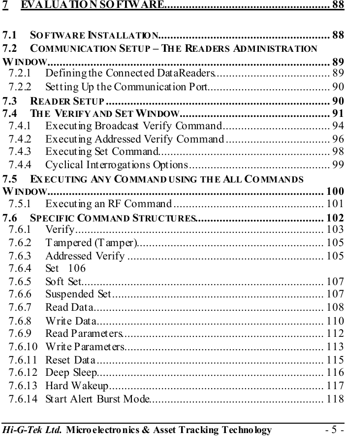
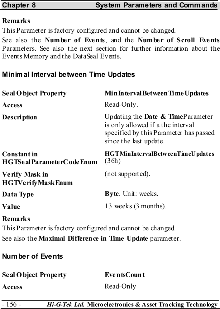
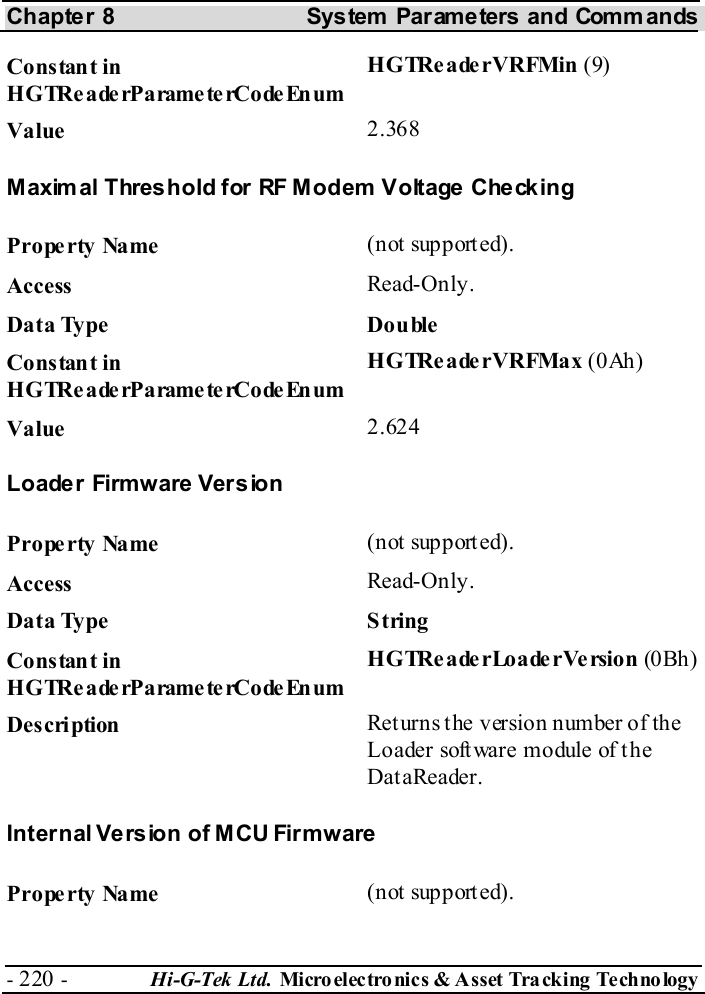
![Chapter 10 Technical Specifications Hi-G-Tek Ltd. Micro electro nics & Asset Tracking Technology - 239 - 10.2 RS232, 24V Outdoor DataReader 24V Outdoor DataReader IG-RS-43D-916 IG-RS-43D-433 IG-RS-43D-318 IG-RS-43D-315 Physical Characteristics Dimensions 195x165x95mm, not including antenna Weight 1000gr Power requirements – External Nominal - 24VDC Mini mum – 10VDC Maximum – 35VDC Power Consumption 1.7W @Tx, 1.1W@Rx Performance Characteristics Interface RS232 Operating frequency [MHz] 916.5 433.92 318 315 Read Range 30m @ open space Environmental Conditions Operating Temperature -40ºC — 70ºC Storage Temperature -40ºC — 70ºC Humidity 90% Non condensing Mechanical Vibration As per MIL-810D & SAE J1455 Mechanical Shock As per MIL-810D & SAE J1455 Standards Designed according to FCC part 15C UL1950 EN300220 EN301489 EN60950 UL1950 UL1950](https://usermanual.wiki/Hi-G-Tek/IGRS46D9916/User-Guide-398653-Page-239.png)
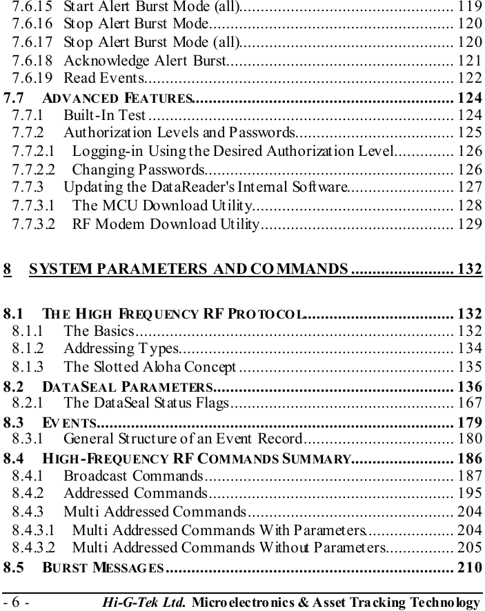
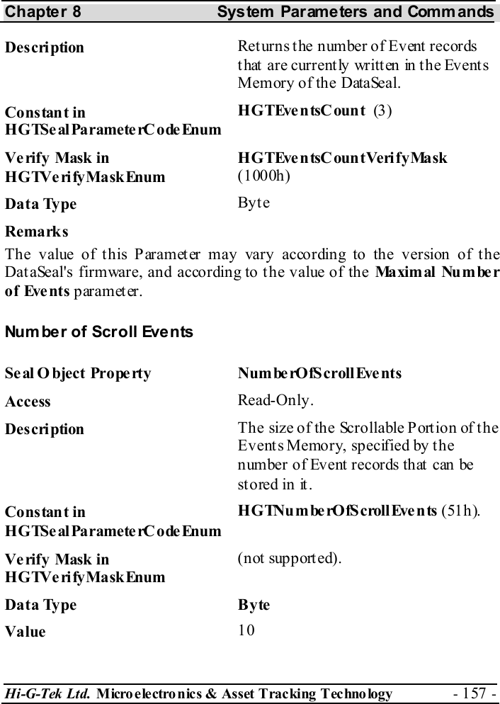
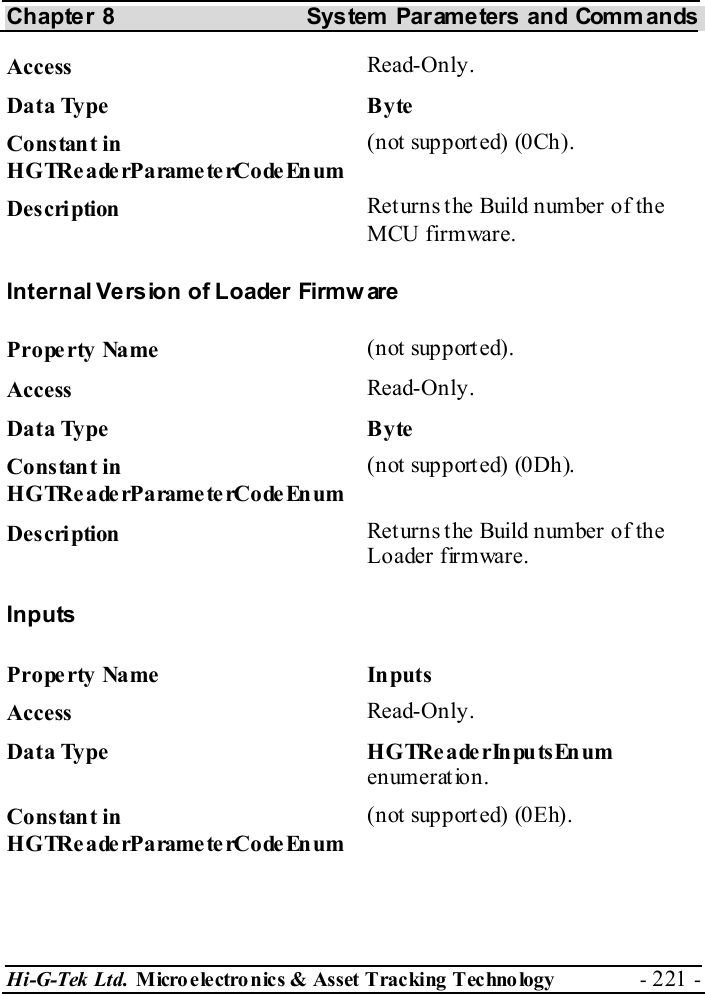
![Chapter 10 Technical Specifications - 240 - Hi-G-Tek Ltd. Micro elec tro nics & A sset Tra cking Techno logy 10.3 Specific- 24V Outdoor DataReader 24V Outdoor DataReader IG-RS-46D9-916 IG-RS-43D9-916 Physical Characteristics Dimensions 195x165x95mm, not including antenna Weight 1000gr Power requirements – External Nominal - 24VDC Mini mum – 10VDC Maximum – 35VDC Power Consumption 1.7W @Tx, 1.1W@Rx Performance Characteristics Interface RS485optically isolated RS232 Operating frequency [MHz] 916.5 Read Range Antenna dependant Environmental Conditions Operating Temperature -40ºC — 70ºC Storage Temperature -40ºC — 70ºC Humidity 90% Non condensing Mechanical Vibration As per MIL-810D & SAE J1455 Mechanical Shock As per MIL-810D & SAE J1455 Standards Designed according to FCC part 90, FCC part 15B UL1950](https://usermanual.wiki/Hi-G-Tek/IGRS46D9916/User-Guide-398653-Page-240.png)
![Chapter 10 Technical Specifications - 242 - Hi-G-Tek Ltd. Micro elec tro nics & A sset Tra cking Techno logy 10.6 24V Indoor DataReader 24V Indoor DataReader IG-RS-46-916 IG-RS-46-433 IG-RS-46-318 IG-RS-46-315 Physical Characteristics Dimensions 195x165x95mm, not including antenna Weight 1000gr Power requirements – External Nominal - 24VDC Mini mum – 10VDC Maximum – 35VDC Power Consumption 1.7W @Tx, 1.1W@Rx Performance Characteristics Interface RS485 optically isolated Operating frequency [MHz] 916.5 433.92 318 315 Read Range 30m @ open space Environmental Conditions Operating Temperature 0ºC — 70ºC Storage Temperature -20ºC — 70ºC Standards Designed according to FCC part 15.249 UL1950 EN300220 EN301489 EN60950 UL1950 UL1950](https://usermanual.wiki/Hi-G-Tek/IGRS46D9916/User-Guide-398653-Page-242.png)
![Chapter 10 Technical Specifications - 244 - Hi-G-Tek Ltd. Micro elec tro nics & A sset Tra cking Techno logy 10.9 DataSeal DataSeal IG-RS-40-916 IG-RS-40-433 IG-RS-40-318 IG-RS-40-315 Physical Characteristics Dimensions 49x37x35mm Weight 100gr Housing P la sti c rei n force d wi th fi be rgl a ss Power Internal 3.6V battery User Memory 2048 bytes Ev ents Memory 55 Performance Characteristics Interface Mounting cradle p/n IG-DH-40 Operating frequency [MHz] 916.5 433.92 318 315 Read Range 30m @ open space Operating frequency 125KHz Read Range 50cm Environmental Conditions Operating Temperature -40ºC — 70ºC Storage Temperature -40ºC — 70ºC Humidity 90% non condensing Mechanical Vibration As per MIL-810D & SAE J1455 Mechanical Shock As per MIL-810D & SAE J1455 Standards Designed according to FCC part 15.249 EN300220 EN301489 Antenna Characteristics Beam Divergence Omni-directional on non-metal wall. Hemisphere on metal wall. Polarization Vertical](https://usermanual.wiki/Hi-G-Tek/IGRS46D9916/User-Guide-398653-Page-244.png)
![Chapter 10 Technical Specifications Hi-G-Tek Ltd. Micro electro nics & Asset Tracking Technology - 245 - 10.10 Magnetic DataSeal Magnetic DataSeal IG-RS-40M-916 IG-RS-40M-433 IG-RS-40M-318 IG-RS-40M-315 Physical Characteristics Dimensions 49x37x35mm Weight 100gr Housing P la sti c rei n force d wi th fi be rgl a ss Power Internal 3.6V battery User Memory 2048 bytes Ev ents Memory 55 Performance Characteristics Operating frequency [MHz] 916.5 433.92 318 315 Read Range 30m @ open space Operating frequency 125KHz Read Range 50cm Environmental Conditions Operating Temperature -40ºC — 70ºC Storage Temperature -40ºC — 70ºC Humidity 90% non condensing Mechanical Vibration As per MIL-810D & SAE J1455 Mechanical Shock As per MIL-810D & SAE J1455 Standards Designed according to FCC part 15.249 EN300220 EN301489 Antenna Characteristics Beam divergence Omni-directional on non-metal wall. Hemisphere on metal wall. Polarization Vertical](https://usermanual.wiki/Hi-G-Tek/IGRS46D9916/User-Guide-398653-Page-245.png)