Hitachi America HSS-MUR-300 RFID Reader User Manual SR2500UserCOR
Hitachi America, Ltd. RFID Reader SR2500UserCOR
UserManual.wiki
>
Hitachi America
>
HSS MUR 300 User Manual
Users Manual
Navigation menu
Upload a User Manual
Namespaces
Wiki Guide
HTML
PDF
Info
Views
User Manual
Discussion / Help
Navigation
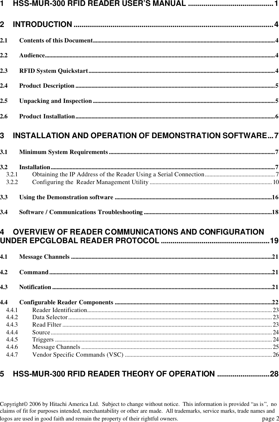
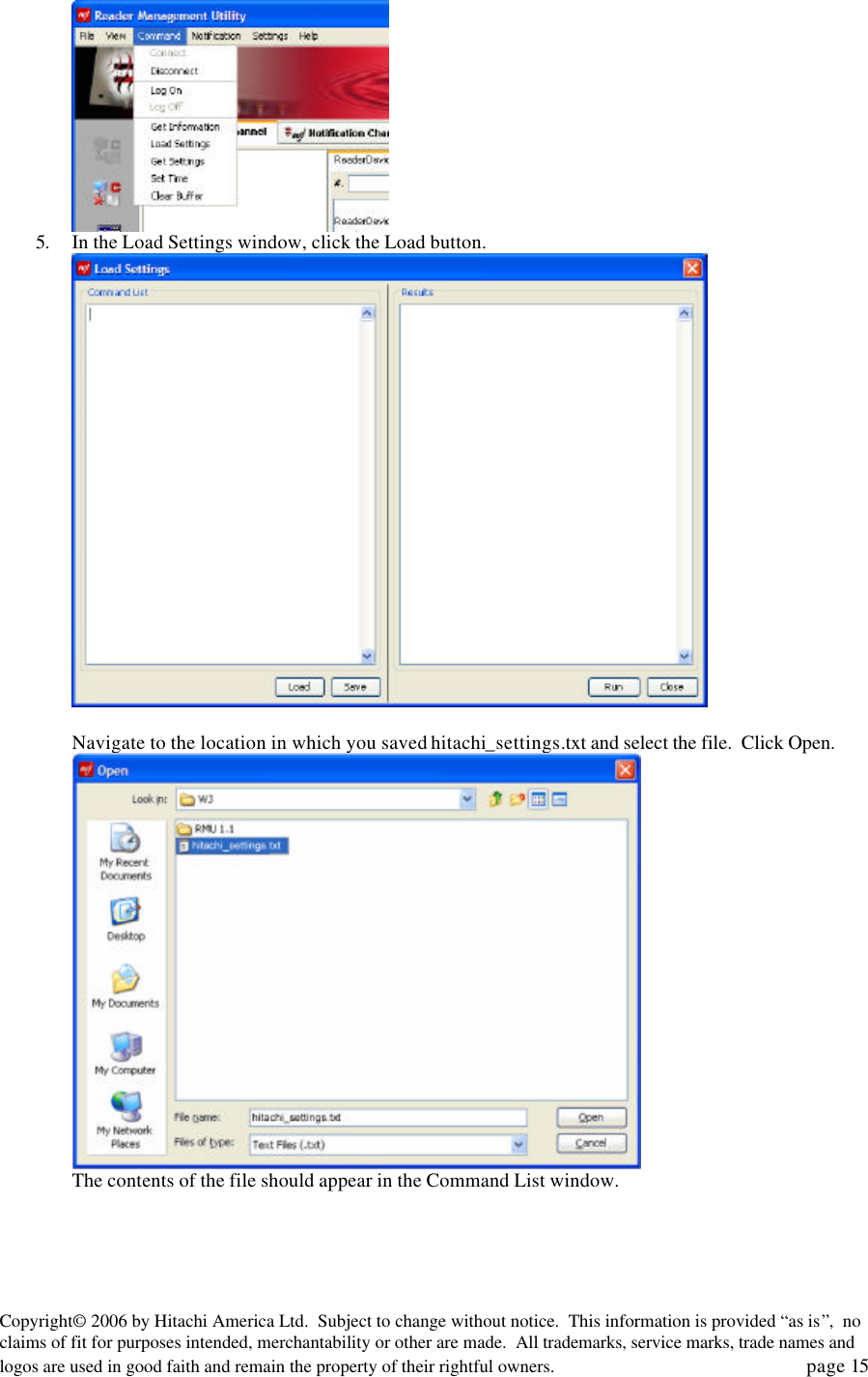
![Copyright© 2006 by Hitachi America Ltd. Subject to change without notice. This information is provided “as is”, no claims of fit for purposes intended, merchantability or other are made. All trademarks, service marks, trade names and logos are used in good faith and remain the property of their rightful owners. page 13 2. Select Settings:Edit Properties. 3. Set the Command IP address to the IP address of the HSS-MUR-300 reader obtained in section 1.2.2.1 above. Set the Command Port to 4684. Click Save. The host computer is now configured to issue commands to the Reader. 4. We now need to configure the host computer to listen to the Notification Channel, to receive information about tags read by the reader. Select Settings:Windows:Start nchannel. 5. After a moment, the Notification Channel 0.0.4 window will appear. [Note that this is a separate application, launched from Reader Management Utility.] Click Listen. You may see a security message if you have a firewall active on your host computer; click Unblock to allow the Notification Channel application to connect.](https://usermanual.wiki/Hitachi-America/HSS-MUR-300/User-Guide-661595-Page-13.png)
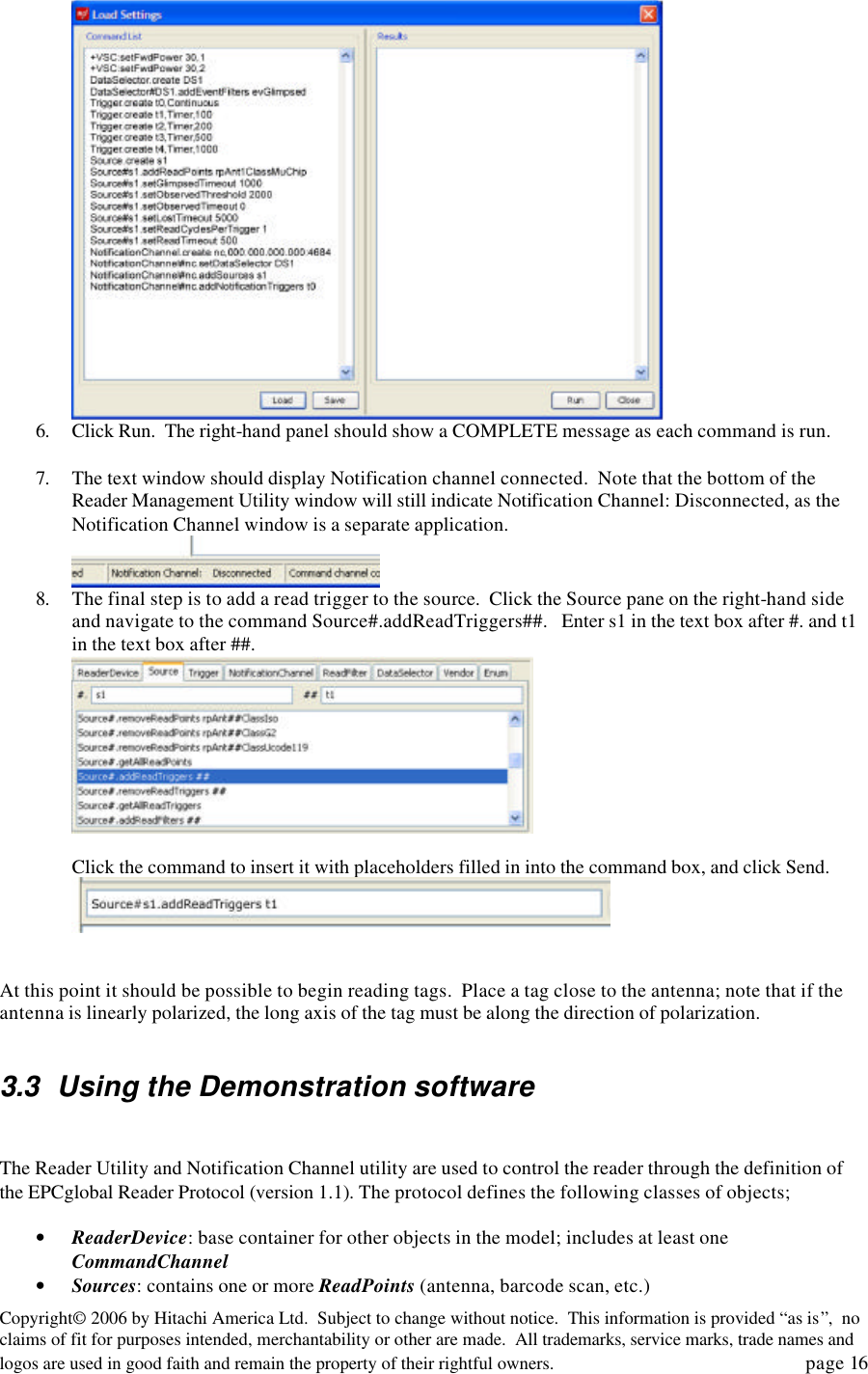
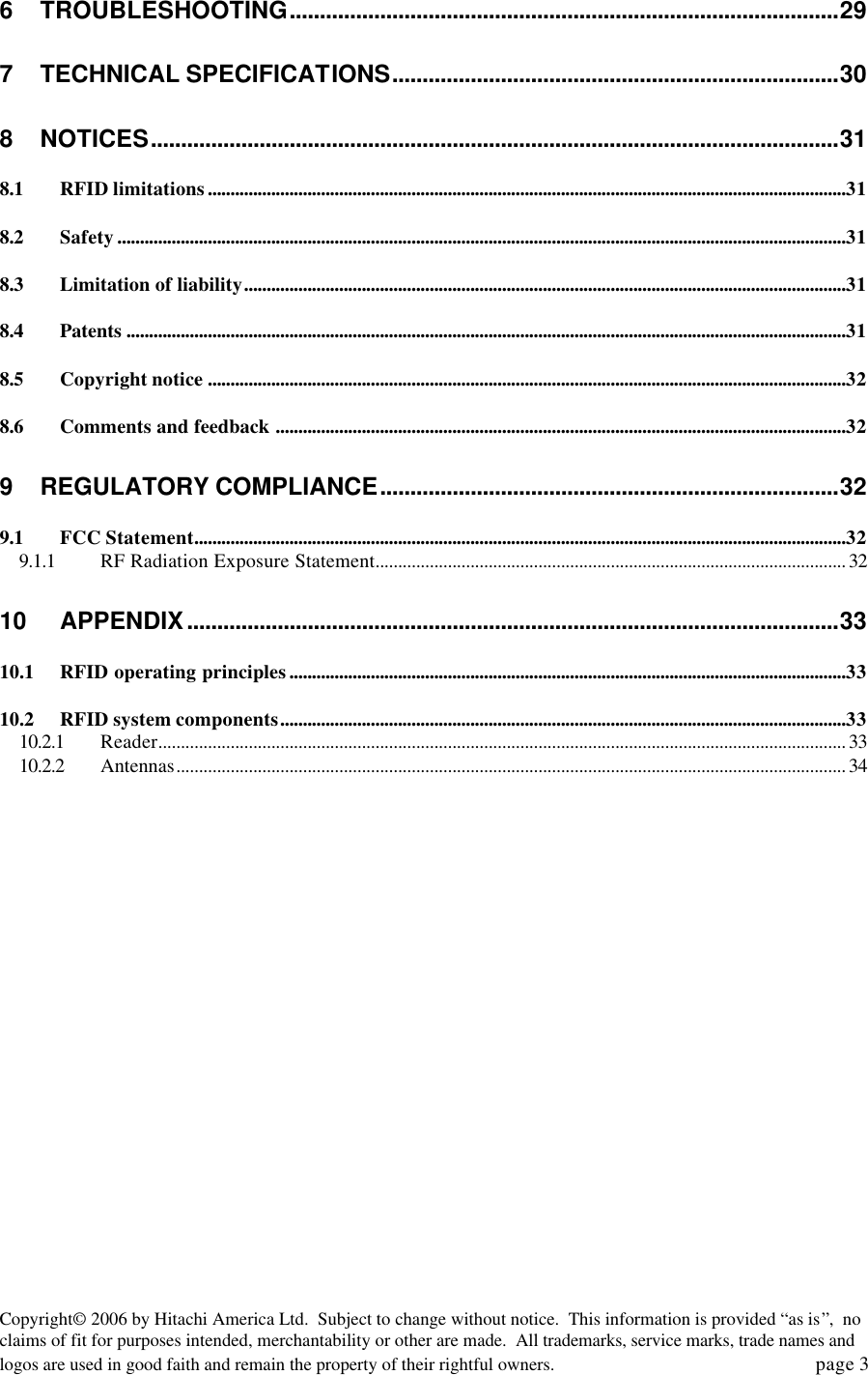
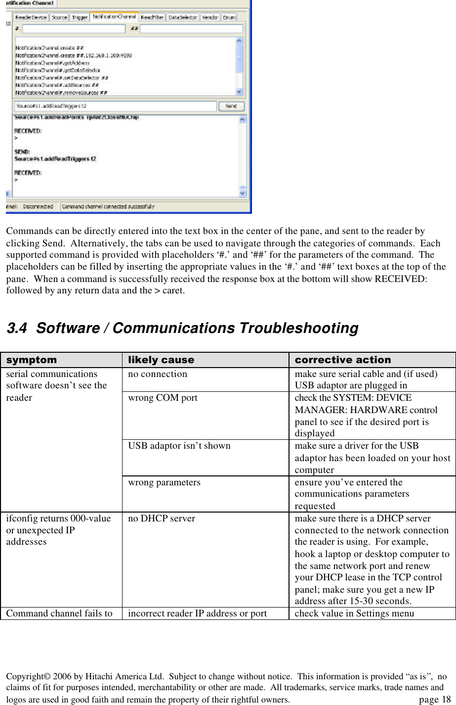
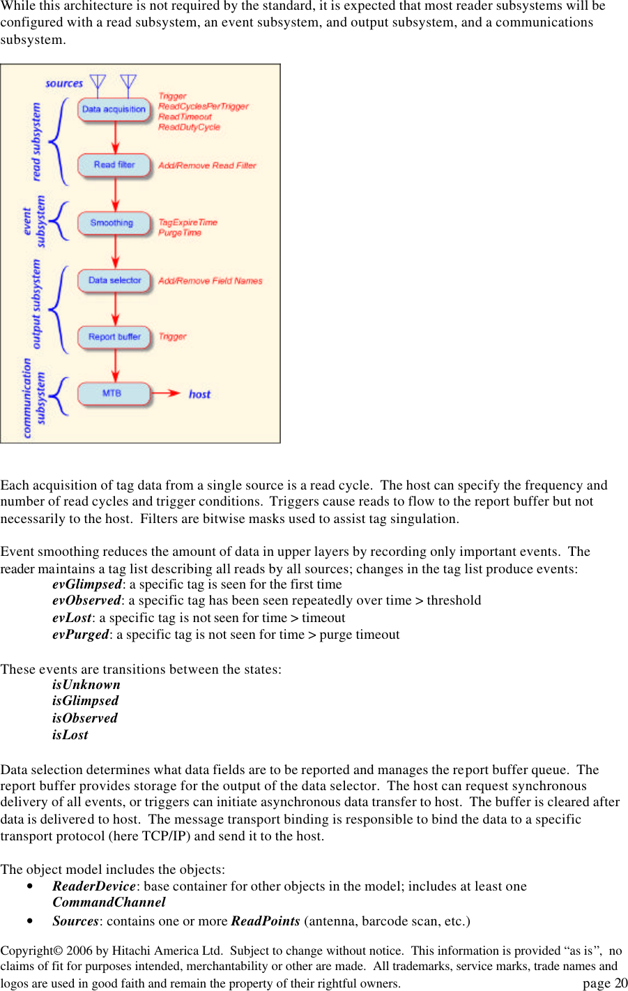
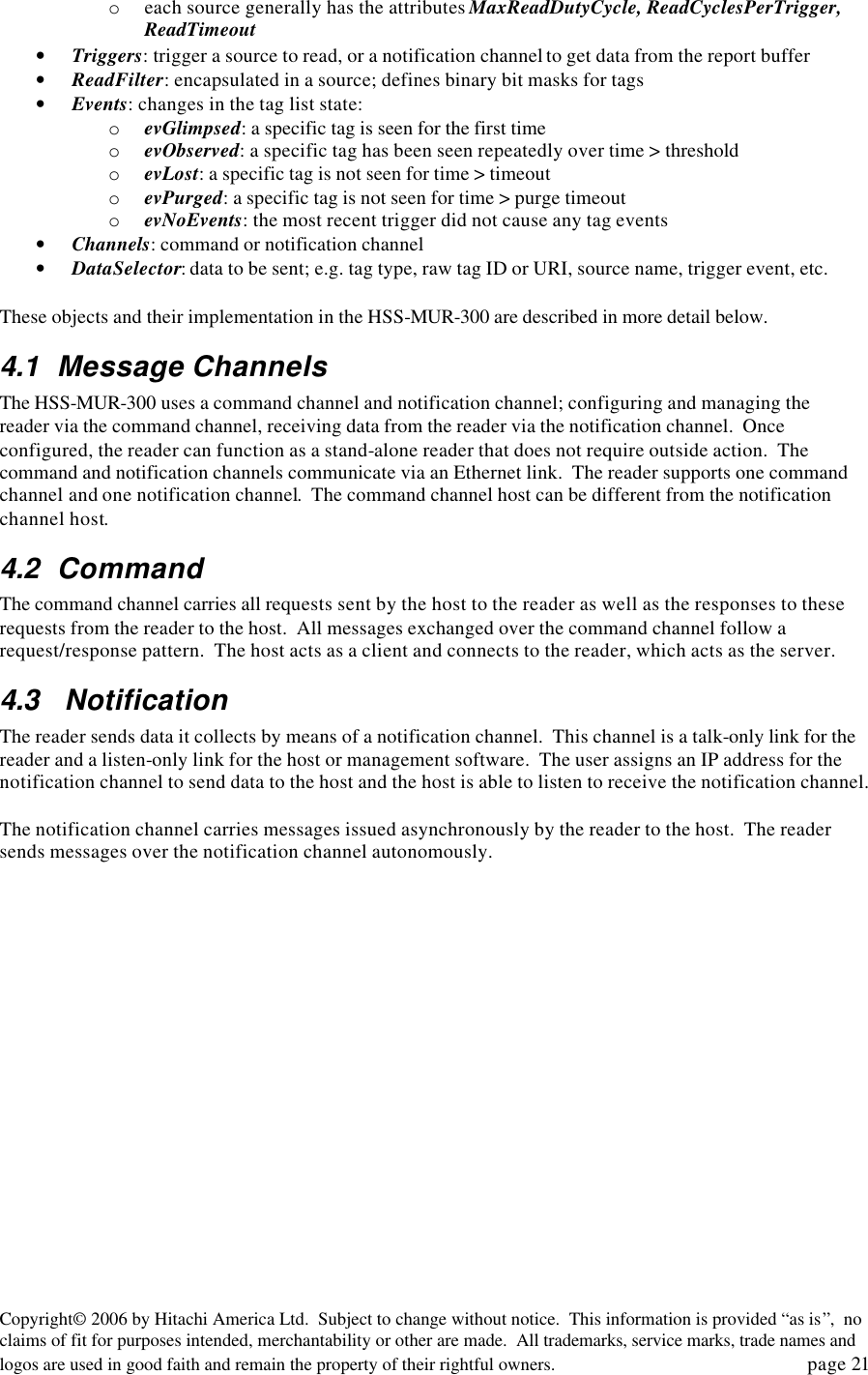
![Copyright© 2006 by Hitachi America Ltd. Subject to change without notice. This information is provided “as is”, no claims of fit for purposes intended, merchantability or other are made. All trademarks, service marks, trade names and logos are used in good faith and remain the property of their rightful owners. page 17 o each source generally has the attributes MaxReadDutyCycle, ReadCyclesPerTrigger, ReadTimeout • Triggers: trigger a source to read, or a notification channel to get data from the report buffer • ReadFilter: encapsulated in a source; defines binary bit masks for tags • Events: changes in the tag list state: o evGlimpsed: a specific tag is seen for the first time o evObserved: a specific tag has been seen repeatedly over time > threshold [1] o evLost: a specific tag is not seen for time > timeout o evPurged: a specific tag is not seen for time > purge timeout [1] o evNoEvents: the most recent trigger did not cause any tag events • Channels: command or notification channel • DataSelector: data to be sent; e.g. tag type, raw tag ID or URI, source name, trigger event, etc. note 1: these events are not yet implemented in the Reader Management Utility To read a tag, the reader needs a command channel, at least one source with at least one read point, and at least one trigger for that read point. The read point is predefined to be assigned to one of the Antenna objects corresponding to the two physical antennas. To report the tag events to the host, the object also needs at least one notification channel, and a data selector with at least one data item (such as the tag ID) selected for reporting. All these objects should have been configured when you loaded the recreate_nc.txt file. If some of the objects are missing, you can use the Reader Management Utility to add them. You can also change the configuration of the reader to suit your requirements; e.g., you can add a continuous trigger or a timed trigger, or you can set up a filter that reports only tags that have been observed (read multiple times) rather than glimpsed (read once). The Reader Management Utility provides a pane on the left side to display the reader object’s current state, a set of panes on the right side to send Reader Protocol commands to the reader to change its state, and a set of menu commands for other specific purposes. To find the current configuration of the reader’s object model, click on the Get Reader Information button. The left-hand window will then be populated with a tree diagram depicting the state of the virtual reader. Click on the [+] symbols to expand the tree any object and show what objects it contains. You can issue Reader Protocol commands to the reader using the right-hand panels.](https://usermanual.wiki/Hitachi-America/HSS-MUR-300/User-Guide-661595-Page-17.png)
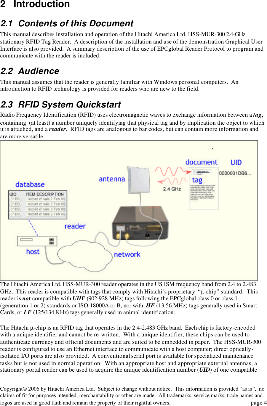
![Copyright© 2006 by Hitachi America Ltd. Subject to change without notice. This information is provided “as is”, no claims of fit for purposes intended, merchantability or other are made. All trademarks, service marks, trade names and logos are used in good faith and remain the property of their rightful owners. page 23 o Timer – the activity is triggered at regular time intervals. o IO Edge – the activity is triggered by a signal transition at an IO port. o IO Value – the activity is triggered by a value (using multiple GPIO pins) match at the IO port. • Read Point – Controls the reading of a single tag type using a single TX/RX antenna pair. • Read Filter – Defines the specific Tag Identities to be included in (or exc luded from) the tag event smoothing and Tag Event generation operations. • Notification Channel – A TCP/IP port Ethernet connection used to send tag data event report messages to a host computer. • Data Selector – Defines the field names data, and the tag event data for event types to be sent in the Tag Data Event Report messages for a ReadIDs command, or for the Notification Channel. • Field Names – Defines the Fields (by name) for which a value is to be reported in each Tag Data Event Report message associated with the Data Selector. • Event Type – Defines which Tag Identities with the corresponding Event Type(s) are to be reported in each tag data read Report message associated with the Data Selector. Only Tag ID events matching the specified Event Type(s) are included in the report. Read and Notification Trigger – Definition of automatic control mechanisms to provide autonomous reader operation for tag reading and report generation of tag events. The following sections provide a simple set of example commands for configuring the HSS-MUR-300 RFID reader. 4.4.1 Reader Identification Assign the reader a unique identifying name ‘RFID Reader’: Format: ReaderDevicesetName [Name] Example: ReaderDevice.setName RFID Reader 4.4.2 Data Selector Create a data selector ‘DS1’ Format: DataSelector.create [Name] Example: DataSelector.create DS1 4.4.2.1 Data Selector Field Name Define the report field name for tag data read reports: Format: DataSelector#[Name].addFieldNames [Name1][Name2]…[NameN] Example: DataSelector#DS1.addFieldNames TagID,ReaderID,ReaderNowTick" 4.4.2.2 Event Report Define event types for tag data event reports: Format: DataSelector#[Name].addEventFilters [FilterName],[FilterName] Example: DataSelector#DS2.addEventFilters evGlimpsed,evLost 4.4.3 Read Filter Create an include read filter ‘I800X’ that Tag IDs that begin with ‘800x8004’ (where ‘x’ is any digit) are processed:](https://usermanual.wiki/Hitachi-America/HSS-MUR-300/User-Guide-661595-Page-23.png)
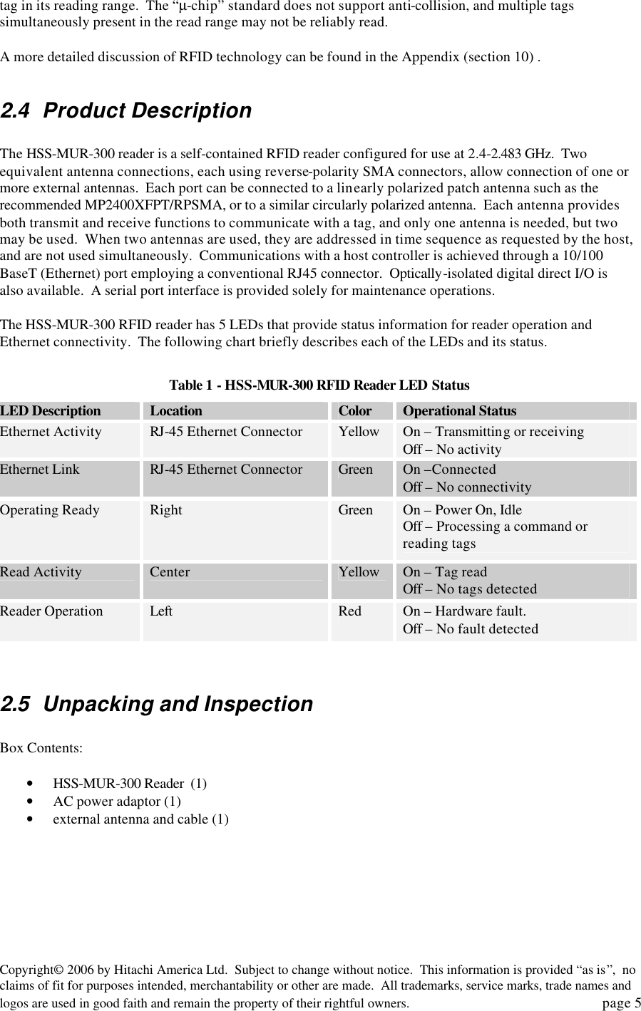
![Copyright© 2006 by Hitachi America Ltd. Subject to change without notice. This information is provided “as is”, no claims of fit for purposes intended, merchantability or other are made. All trademarks, service marks, trade names and logos are used in good faith and remain the property of their rightful owners. page 24 Format: ReadFilter.create [Name],[TagID],[Boolean] • "ReadFilter.create I800X,80008004,FFF0FFFF,true" Create an exclude read filter (‘X8001’) that Tag IDs that begin with ‘8001’ will be excluded: • "ReadFilter.create X8001,8001,FFFF,false" 4.4.4 Source Create the source object ‘dock_door’: Format: Source.create [Name] Example: Source.create dock_door 4.4.4.1 Read Point Assign Read Points ‘rpAnt1ClassMuChip’ (read µ-Chips using Antenna 1) which identify the class of tags, and the Antenna for a single tag data read: Format: Source#[Source].addReadPoints rpAnt[Antenna][Tag Class] Example: Source#dock_door.addReadPoints rpAnt1ClassMuChip Issue a raw read command to perform a single tag data read operation with all tag data reported on the command channel DS1 to control the report formatting): Format: Source#[Source].rawReadIDs [Data Selector] Example: Source#dock_door.rawReadIDs DS1 4.4.5 Triggers 4.4.5.1 Creating Triggers Create a continuous trigger called Notify1 to generate autonomous Tag Data Event Reports: Format: Trigger.create [Name],[Type] Example: Trigger.create Notify1,Continuous Create a timed trigger that causes autonomous tag data read operations every 200 milliseconds: Format: Trigger.create [Name],[Type],[Interval] Example: Trigger.create ReadTimer 200mSec,Timer,200 Create an I/O Edge Trigger that causes autonomous tag data read operations as the result of a Rising Edge on Digital I/O Pin 1 (Port Number is always 1): Format: Trigger.create [Name],[Type],[Edge],1,[Pin] Example: Trigger.create ReadEdgeRising,IOEdge,rising,1,1 Create an I/O Value Trigger that causes autonomous tag data read operations as the result of a configurable value(s) are detected on the Digital I/O Pins (Port Number is always 1). The Mask parameter is optional, it is bitwise anded with the port data before comparing to the mask: Format: Trigger.create [Name],[Type], 1, [Value], [Mask] Example: Trigger.create ReadValue, IOValue, 1, 0002, 0002Read Trigger Add ‘ReadTimer‘ to ‘dock_door’ to read tags autonomously:](https://usermanual.wiki/Hitachi-America/HSS-MUR-300/User-Guide-661595-Page-24.png)
![Copyright© 2006 by Hitachi America Ltd. Subject to change without notice. This information is provided “as is”, no claims of fit for purposes intended, merchantability or other are made. All trademarks, service marks, trade names and logos are used in good faith and remain the property of their rightful owners. page 25 Format: Source#[Source].addReadTriggers [Trigger] Example: Source#dock_door.addReadTriggers ReadTimer Add the ‘ReadEdge‘ read trigger to cause autonomous tag data read operations when a rising edge signal is detected on digital I/O pin 1: Format: Source#[Source].addReadTriggers [Name] [I/O Pin] [Edge] Example: Source#dock_door.addReadTriggers ReadEdge 1 Rising Add read filter ‘I800X’ to cause only tags that begin with ‘800x8004’ (where ‘x’ is any digit) to be processed: Format: Source#[Source].addReadFilters [Filter] Example: Source#front_door.addReadFilters I800X 4.4.6 Message Channels 4.4.6.1 Command Channel In order to modify the IP Address, NetMask, and Port Number for the HSS-MUR-300 RFID Reader Command Channel, it is necessary to set Administrative Mode and then issue the command to set the new Command Channel values: Enter Admin mode: Format: +HAL:adminMode [Password] Example: +HAL:adminMode HALcomm Change the reader’s IP address: Format: +HAL:setIPaddr [Type],[IP Address],[NetMask],[Port] Example: +HAL:setIPaddr static,192.168.1.200,255.255.255.0,4599 4.4.6.2 Notification Channel Create the notification channel ‘NC1’ for autonomous tag data event reports: Format: NotificationChannel.create [Channel Name],[IP Address]:[Port] Example: NotificationChannel.create NC1,192.168.1.1:4684 Assign the data selector ‘DS1’ to the notification channel ‘NC1’: Format: NotificationChannel#[Channel Name].setDataSelector [Selector Name] Example: NotificationChannel#NC1.setDataSelector DS1 Assign the source ‘dock_door 1’ to the notification channel ‘NC1’ Format: NotificationChannel#[Channel Name].addSources [Source] Example: NotificationChannel#NC1.addSources dock_door 1" Assign the continuous notification trigger ‘Cont’ to the notification channel ‘NC1’: Format: NotificationChannel#[Channel Name].addNotificationTriggers[Trigger] Example: NotificationChannel#NC1.addNotificationTriggers Cont These commands capture autonomous tag data events from ‘dock_door 1’ and tag data event reports are sent on the notification channel. The ‘DS2’ Data Selector to controls the report format.](https://usermanual.wiki/Hitachi-America/HSS-MUR-300/User-Guide-661595-Page-25.png)
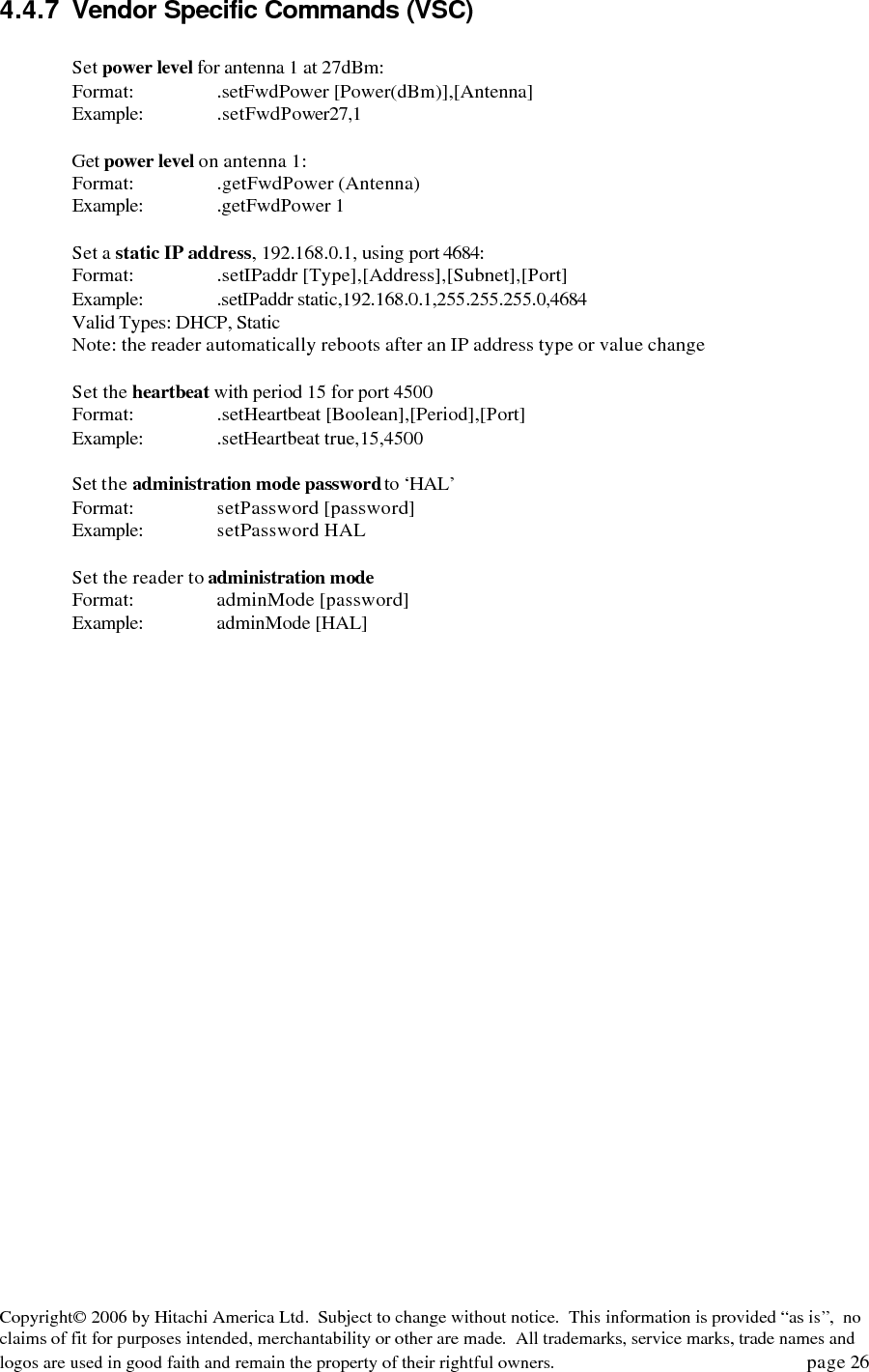
![Copyright© 2006 by Hitachi America Ltd. Subject to change without notice. This information is provided “as is”, no claims of fit for purposes intended, merchantability or other are made. All trademarks, service marks, trade names and logos are used in good faith and remain the property of their rightful owners. page 26 4.4.7 Vendor Specific Commands (VSC) Set power level for antenna 1 at 27dBm: Format: .setFwdPower [Power(dBm)],[Antenna] Example: .setFwdPower27,1 Get power level on antenna 1: Format: .getFwdPower (Antenna) Example: .getFwdPower 1 Set a static IP address, 192.168.0.1, using port 4684: Format: .setIPaddr [Type],[Address],[Subnet],[Port] Example: .setIPaddr static,192.168.0.1,255.255.255.0,4684 Valid Types: DHCP, Static Note: the reader automatically reboots after an IP address type or value change Set the heartbeat with period 15 for port 4500 Format: .setHeartbeat [Boolean],[Period],[Port] Example: .setHeartbeat true,15,4500 Set the administration mode password to ‘HAL’ Format: setPassword [password] Example: setPassword HAL Set the reader to administration mode Format: adminMode [password] Example: adminMode [HAL]](https://usermanual.wiki/Hitachi-America/HSS-MUR-300/User-Guide-661595-Page-26.png)
![Copyright© 2006 by Hitachi America Ltd. Subject to change without notice. This information is provided “as is”, no claims of fit for purposes intended, merchantability or other are made. All trademarks, service marks, trade names and logos are used in good faith and remain the property of their rightful owners. page 30 tag environment tags cannot be read when resting directly on metal object or object containing aqueous fluids; provide 1-2 cm spacing from such objects reader antenna environment no metal obstacles should be present between reader antenna and tag Tag read sporadically interference check vicinity for likely interferers, including active WiFi (802.11) client or basestation, active Bluetooth client or basestation, cordless telephone operating at 2.4 GHz band 7 Technical specifications PHYSICAL: Parameter Specification Dimensions 140 mm (5.50”) Length x 105 mm (4.13”) Width x 32 mm (1.25”) Height Weight 0.545 Kgm (1 lb 3.2 oz) Chassis Material Aluminum Antenna ports 2 Antenna connectors reverse-polarity SMA Network ports 1 (RJ45) Serial communications 1 (Female DB9) GPIO male DB15 Power 2.1 mm ID (pin positive); 5.5 mm OD (GND), 12 mm insert length ELECTRICAL / PERFORMANCE: Parameter Specification DC power 6 VDC, 24 watts; recommended power supply : CVI PN DTS060400UDC Operating Frequency US ISM band (2.4 –2.483 GHz) Frequency-hopping: 75 channels at 1MHz spacing Maximum transmit power 28.0 dBm Protocol support Hitachi µ-chip Read range 30 cm typical Operating temperature -10 to 55°C (-14 to 132°F) Recommended antennas MP2400XFPT/RPSMA (linear polarized) HG2409PCR (RHCP) or HG2409PCL (LHCP) Antenna Max Gain 8.5 dBi, 8.0 dBiC; 1 meter (3 foot) cable; see note [1] COMMUNICATIONS: Parameter Specification network port 10/100 BASE T (Ethernet) serial port RS232 host interface complies with EPCGlobal draft Reader Host Specification 6-27-05 GPIO see note [2] HARDWARE / OS: Parameter Specification Processor Cirrus Logic EP9302 ARM9 Core Memory 32MB Flash; 32MB SDRAM Operating System Debian Linux Kernel V2.4](https://usermanual.wiki/Hitachi-America/HSS-MUR-300/User-Guide-661595-Page-30.png)
![Copyright© 2006 by Hitachi America Ltd. Subject to change without notice. This information is provided “as is”, no claims of fit for purposes intended, merchantability or other are made. All trademarks, service marks, trade names and logos are used in good faith and remain the property of their rightful owners. page 31 [1] Antennas of similar type (panel or patch) and the same or lower gain may be substituted for the recommended antenna. Antenna gains listed above do not include 0.6 dB cable loss, which must be added to published antenna gains to calculate effective antenna gain. Use of antennas with higher effective gain than the recommended antenna may lead to failure of the unit to comply with applicable standards for unlicensed operation in the United States. [2] The HSS-MUR-300 RFID Reader provides 4 externally accessible digital inputs and 4 outputs. These inputs are optically isolated (positive or negative, up to 30V differential) for external event sensing. The 4 digital outputs (on/off MOSFET switch operation up to 30V differential) control external devices. 8 Notices 8.1 RFID limitations Communication between tags and readers at 2.4 GHz is a complex phenomenon depending on details of the environment surrounding the tags and reader(s) as well as the equipment being used. Some environmental aspects (such as tag placement and orientation) may be controllable by the user; others (such as reflections of the RF radiation by ambient objects) are generally not. Careful installation and testing, and development and adherence to appropriate operating procedures, are indispensable for successful implementation of RFID. Hitachi America Ltd. makes no representation or warrantee that any specific configuration of RFID tags and readers will provide any given performance characteristics. 8.2 Safety Any use of this equipment with antennas or cabling installed outdoors or otherwise exposed to inclement weather must avoid proximity with power lines or other high-voltage conductors, and provide for proper grounding and lightning arresting devices to protect the equipment user in the event of a lightning strike. See National Electrical Code (NEC) requirements articles 725, 800, and 810 for further information. Do not operate the stationary portal readers in any area where critical safety equipment may be sensitive to RF interference, such as medical or life support equipment. Do not operate the stationary portal readers on board any aircraft in flight, or at any other time when operation of radio devices such as cellular phones is prohibited. Personnel should not be closer than 20 cm (8 inches) from any Stationary portal reader antenna for prolonged periods of time. See FCC bulletins 56 and 65 for further information on electromagnetic field exposure. 8.3 Limitation of liability The information in this manual is subject to change without notice and does not represent a commitment on the part of Hitachi America Ltd. Hitachi America Ltd., specifically disclaims liability for any and all direct, indirect, special, general, incidental, consequential, punitive or exemplary damages, including but not limited to loss of profits, revenue, or anticipated loss of profits or revenue, arising out of the use or inability to use any Hitachi America Ltd. product, even if Hitachi America Ltd. has been advised or the possibility of such damages or they are foreseeable, or for claims by any third party. 8.4 Patents Portions of the products described in this manual may be covered by granted or currently-pending US and foreign patents.](https://usermanual.wiki/Hitachi-America/HSS-MUR-300/User-Guide-661595-Page-31.png)
![Copyright© 2006 by Hitachi America Ltd. Subject to change without notice. This information is provided “as is”, no claims of fit for purposes intended, merchantability or other are made. All trademarks, service marks, trade names and logos are used in good faith and remain the property of their rightful owners. page 32 8.5 Copyright notice The contents of this document are the property of Hitachi America Ltd., except where otherwise noted. Individuals who have purchased or otherwise legally acquired the stationary portal reader hardware units described in this document are expressly permitted to make copies of the document, in electronic or paper form, for personal, backup, and archival use. Brief segments may be excerpted and used with attribution for descriptive purposes in commentaries, reviews, or other informational documents. All other reproduction in whole or in part is expressly prohibited without the consent of the copyright owner. Copyright 2006 by Hitachi America Ltd. 8.6 Comments and feedback Comments and feedback on this manual or the HSS-MUR-300 reader are welcomed: By phone: 1-800-WJ1-4401 (951-4401) or (972) 705-2313 By email: RFID.info@wj.com 9 Regulatory Compliance 9.1 FCC Statement This equipment has been tested [PENDING AT THE TIME OF THIS WRITING!] and found to comply with the limits for a Subparts B Class A digital device, pursuant to Part 15 of the FCC Rules. These limits are designed to provide reasonable protection against harmful interference in a residential installation. This equipment generates, uses and can radiate radio frequency energy and, if not installed and used in accordance with the instructions, may cause harmful interference to radio communications. However, there is no guarantee that interference will not occur in a particular installation. If this equipment does cause harmful interference to radio or television reception, which can be determined by turning the equipment off and on, the user is encouraged to try to correct the interference by one or more of the following measures: -- Reorient or relocate the receiving antenna. -- Increase the separation between the equipment and receiver. -- Connect the equipment into an outlet on a circuit different from that to which the receiver is connected. -- Consult the dealer or an experienced radio/TV technician for help. NOTE: Changes or modifications not expressly approved by Hitachi America Ltd. could void the user's authority to operate the equipment described in this manual. 9.1.1 RF Radiation Exposure Statement These devices comply with FCC radiation exposure limits set forth for an uncontrolled environment, and users must follow specific operating instructions for satisfying RF exposure compliance. To comply with FCC RF exposure requirements, a separation distance of at least 20cm must be maintained between the antenna of this device and all persons. This device must not be co-located or operating in conjunction with any other antenna or transmitter.](https://usermanual.wiki/Hitachi-America/HSS-MUR-300/User-Guide-661595-Page-32.png)