Honeywell Analytics Asia Pacific OELD Smart Junction Box for Gas Detectors User Manual OELD Instruction Manual
Honeywell Analytics Asia Pacific Co., Ltd. Smart Junction Box for Gas Detectors OELD Instruction Manual
UserManual.wiki
>
Honeywell Analytics Asia Pacific
>
OELD User Manual
Manual
Navigation menu
Upload a User Manual
Namespaces
Wiki Guide
HTML
PDF
Info
Views
User Manual
Discussion / Help
Navigation
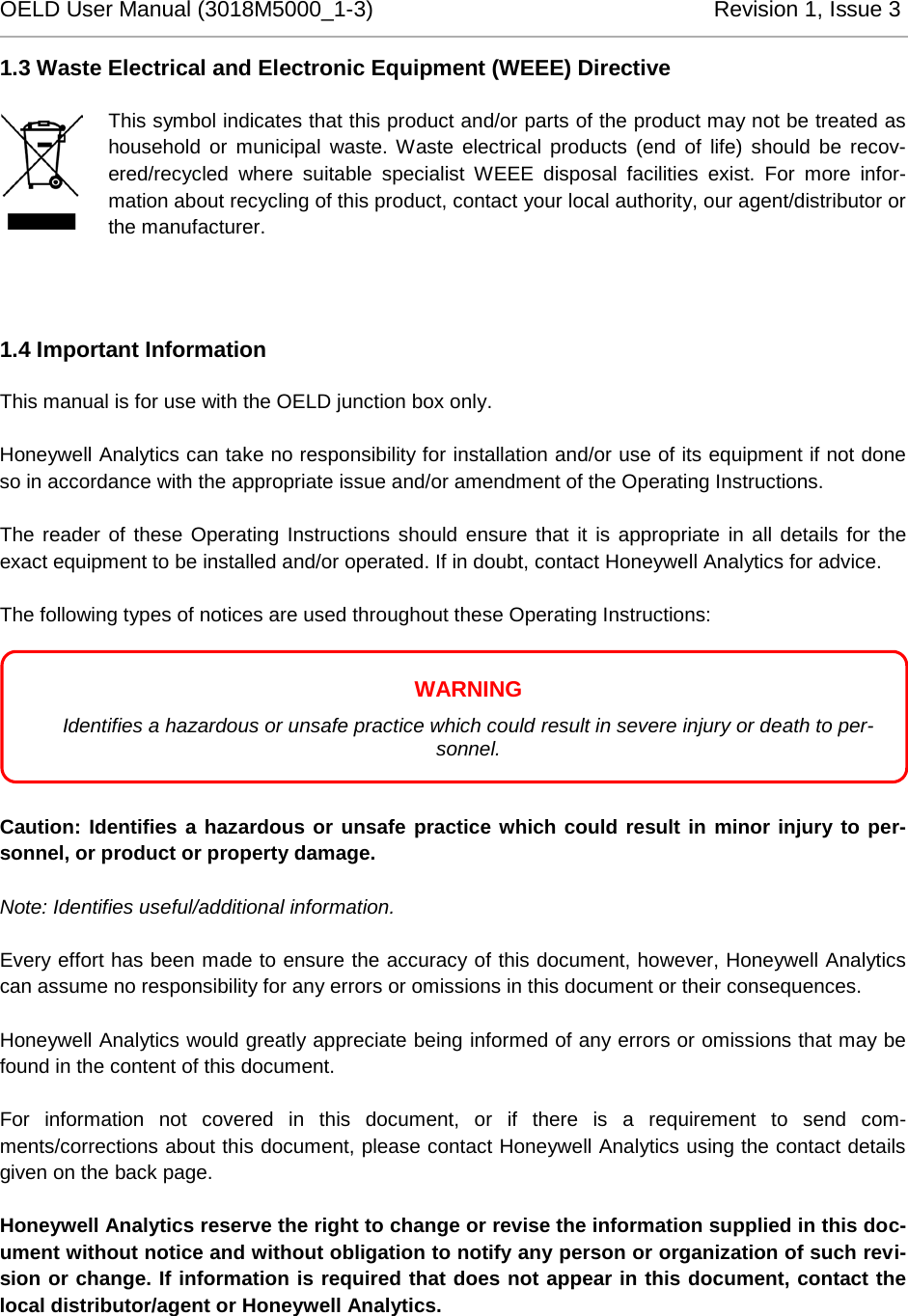
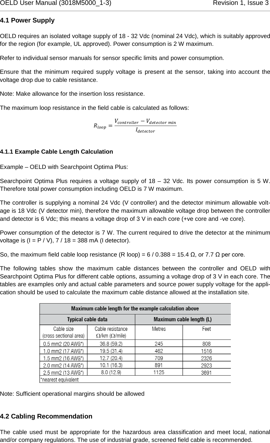

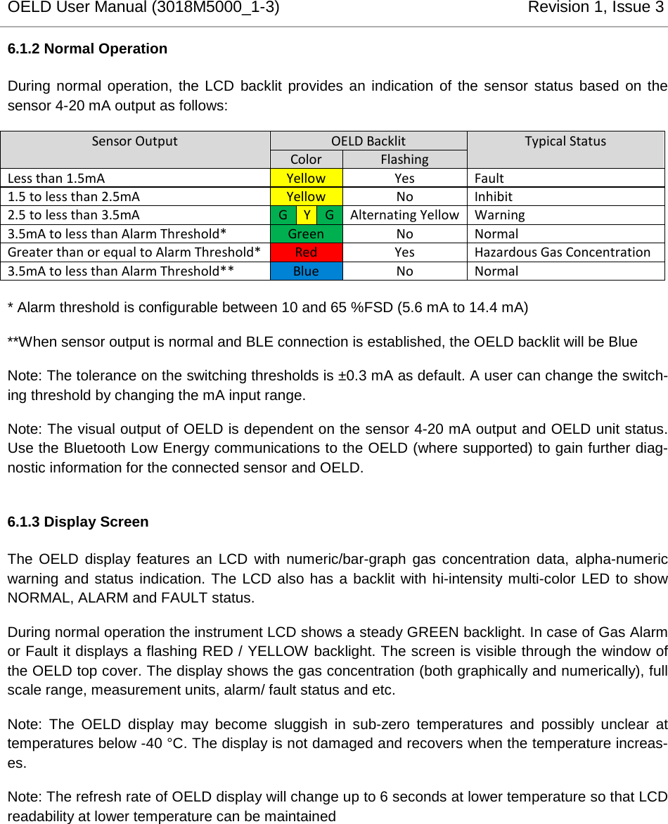

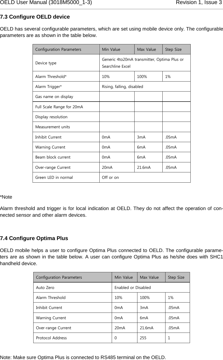
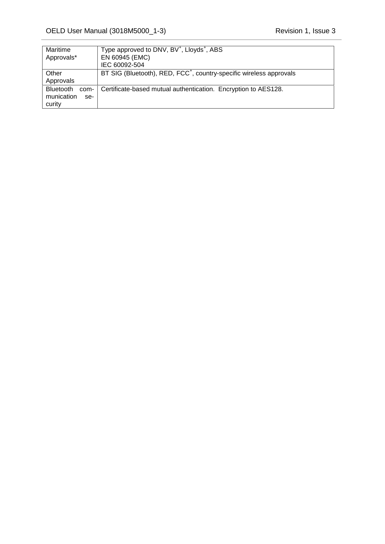
![OELD User Manual (3018M5000_1-3) Revision 1, Issue 3 10 Specifications OELD Specification Material Marine-grade aluminium alloy or 316 stainless steel with 5-coat painted finish Weight Aluminium version 2.3 kg (5 lb), stainless steel version 5.0 kg (11 lb) Dimensions 159 x 197 x 114 mm (6 ¼ x 7 ¾ x 4 ½ inch) Cable entries 5 x M25 (ATEX/IECEx version) or 5 x ¾” NPT (cULus version). One reserved for sensor connection. 3 blanking plugs supplied for unused entries. Termination 2 x pluggable rising-clamp type for connection to gas detector and field wiring. Accepts cable sizes of 0.5 to 2.5mm2, 12 to 28 AWG Storage Temperature -25 to +65 °C (-13 to 149 °F) Operational temperature -40 to +65 °C (-40 to 149 °F) -60 to +65 °C (-76 to 149 °F) with optional heater module+ Humidity (non-condensing) 20 to 90% RH continuous, 0 to 99% RH intermittent Display LCD module showing digital readout of sensor output, bar chart representation, units of measurement, status icons for alarm, maintenance and active Bluetooth connection. Configurable displayed information Displayed information fully user-configurable using the OELD mobile app. Units of measurement (select from %LEL, mg/m3, g/m3, %Vol, ppm, mA, A, kppm, LEL.m, dB, dBA, ppm.m) Gas name (up to 4 alpha-numeric characters) Measurement range Visual indication Green/amber/red/blue multi-colour backlight to display for indication of detector and OELD status. Green (normal) indication can be disabled via app. Power supply 18 to 32 Vdc (24 Vdc nominal), <2 W Interfaces Bluetooth® (BLE) non-intrusive connection to suitable mobile device running the OELD mobile app. Range up to 10 m (mobile device dependant) Internal RS-485 connection to Searchpoint Optima Plus or Searchline Excel via SHC-1 through the protection device Environmental Protection IP66 / Type 4X Core Approvals EN 50270: 2015 (EMC) IEC/EN/UL/CSA 61010 (Electrical Safety) FCC+ RoHS China RoHS+ Safety Approvals ATEX [DEMKO 16 ATEX 1693X] II 2 GD Ex db IIC T6 (flameproof Ex d version) Ex tb IIIC T85°C (flameproof Ex d version) Tamb -40 to +65°C cULus [E484838] Class I, Div 1, B, C & D Class II, E, F & G Class III Tamb -55 to +65°C IECEx [IECEx UL 16.0066X] Ex db IIC T6 (flameproof Ex d version) Ex tb IIIC T85°C (flameproof Ex d version) Tamb -40 to +65°C CU TR-Ex (Russian Customs Union), Tamb -60 to +65°C* CCCF* Inmetro* NEPSI+* PESO+* Assessed to have no effect on functional safety of connected gas sensor](https://usermanual.wiki/Honeywell-Analytics-Asia-Pacific/OELD/User-Guide-3066098-Page-28.png)