Honeywell Analytics Asia Pacific RMBLEM5 Bluetooth Low Energy Module - RMBLE-M5 User Manual RMBLE M5 RMBLE M5 REV2 20160923

Honeywell Analytics Asia Pacific Co., Ltd. Bluetooth Low Energy Module - RMBLE-M5 RMBLE M5 RMBLE M5 REV2 20160923
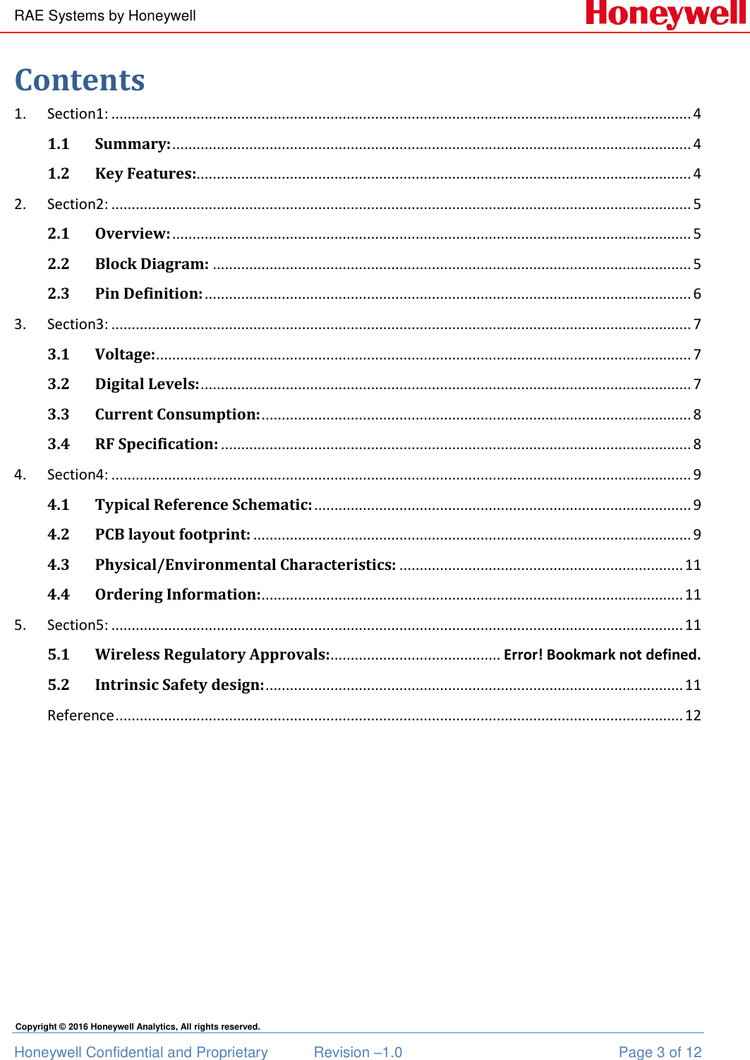
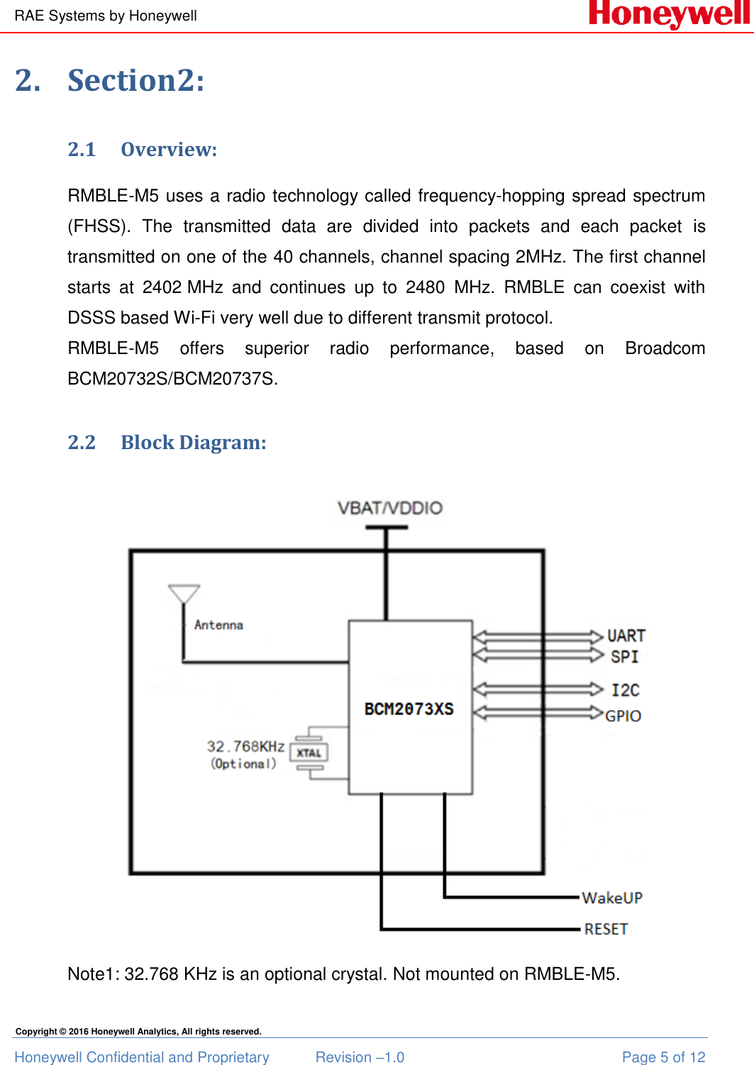
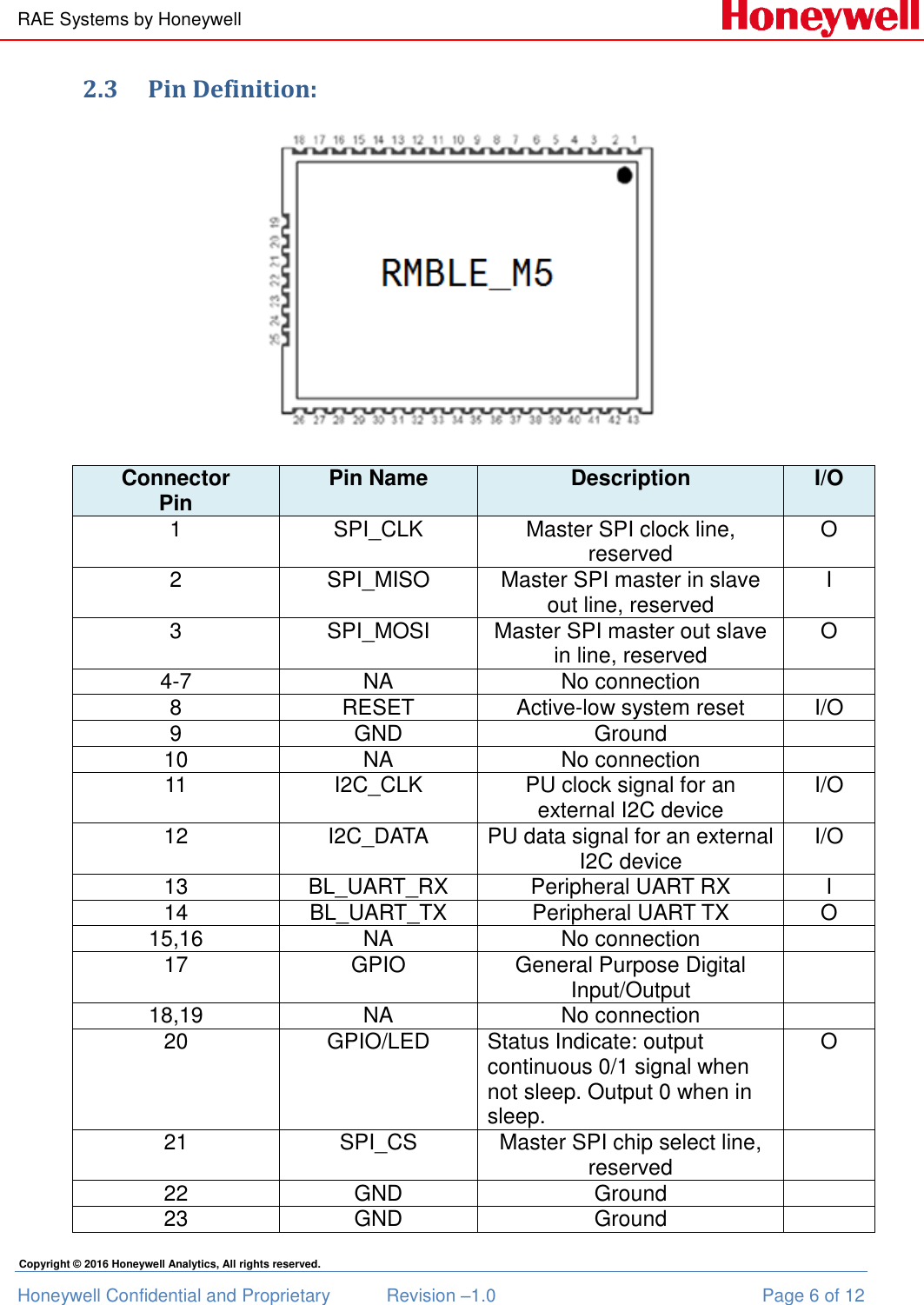
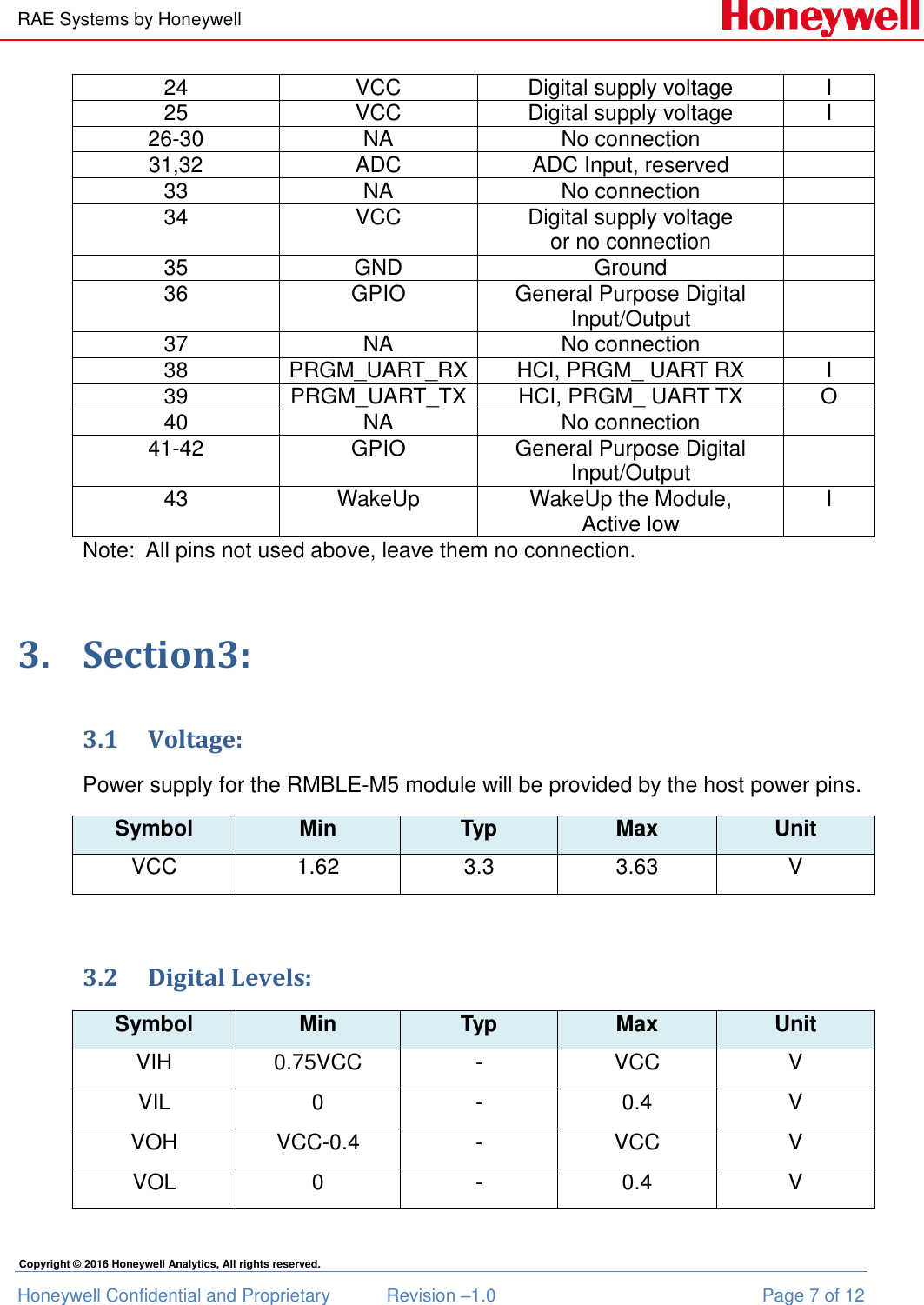
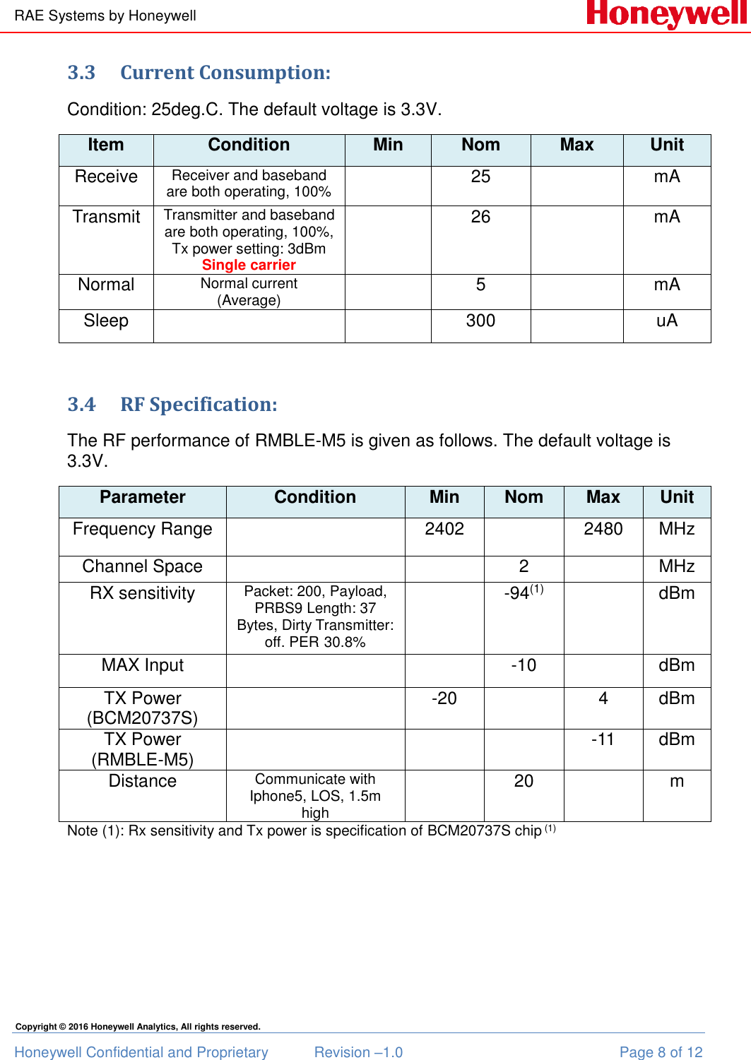
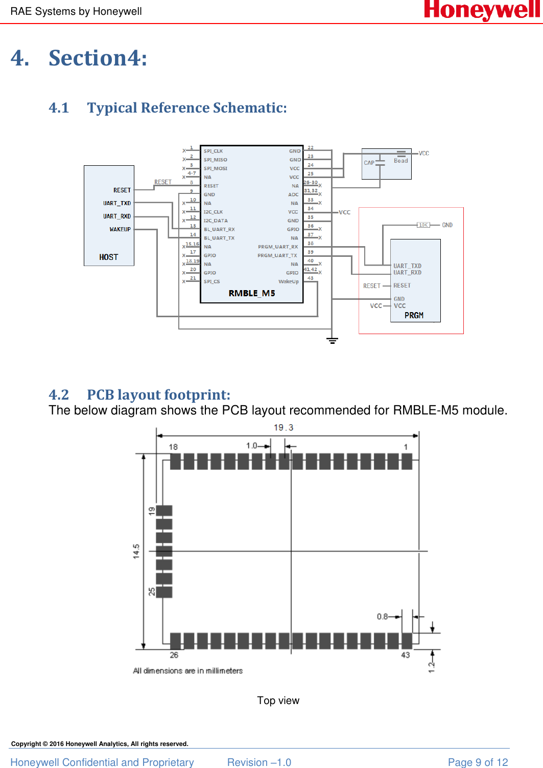
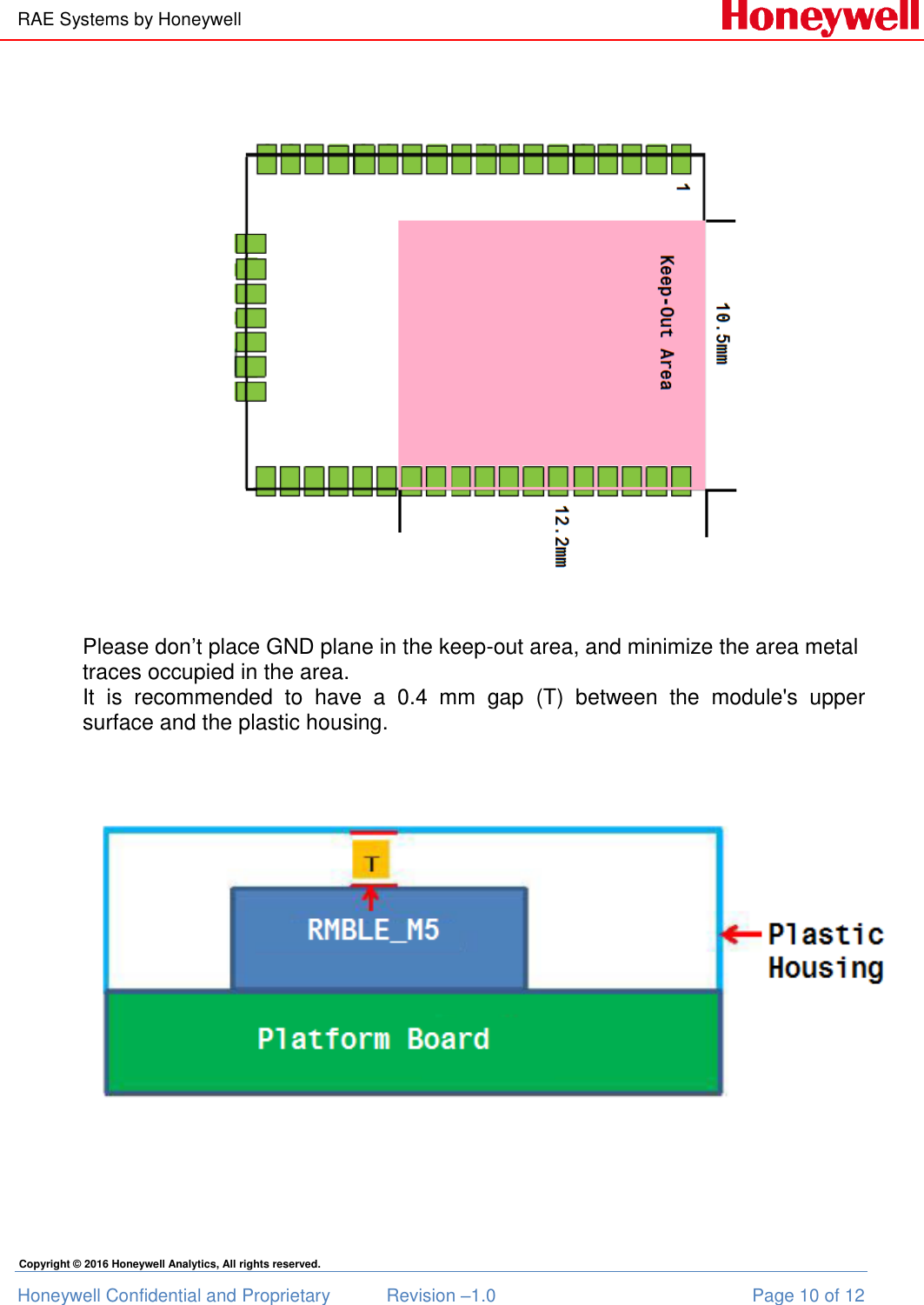
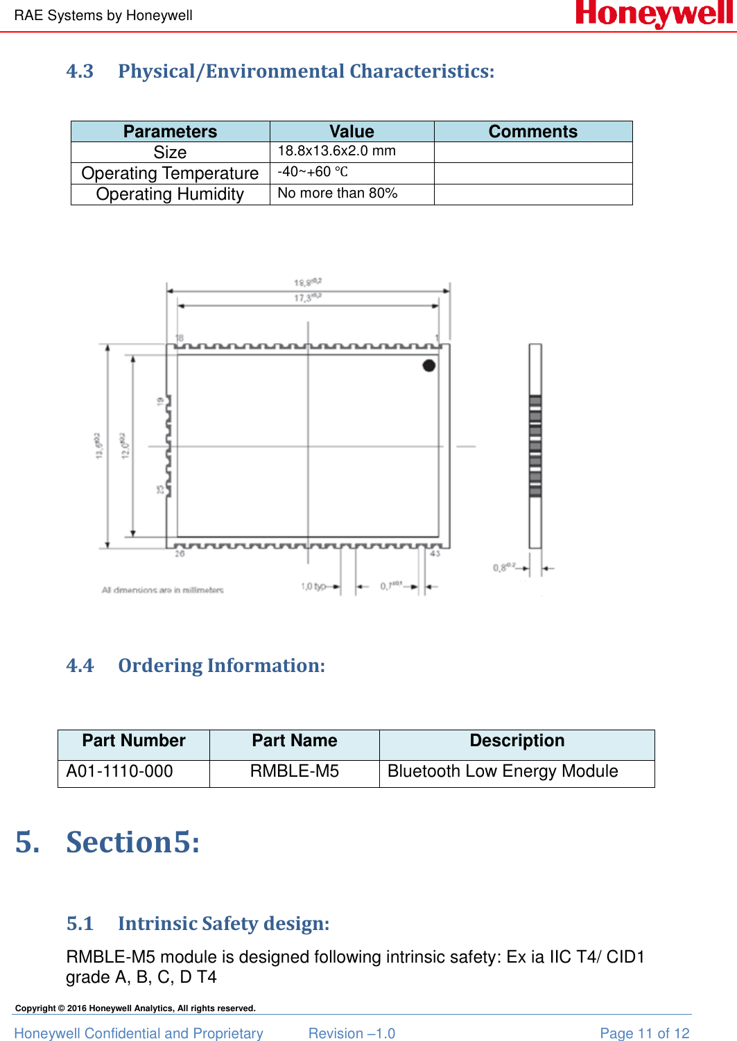
RMBLE-M5 User Manual_RMBLE_M5_REV2 20160923

RAE Systems by Honeywell Honeywell Confidential and Proprietary  Revision –1.0  Page 1 of 12 Copyright © 2016 Honeywell Analytics, All rights reserved.   Bluetooth Low Energy Module RMBLE-M5       Document Information Info Content Author(s) Kong Juan Revision 1.0 Document Status Draft Date  February 26, 2015 Distribution Internal Use Only Approvals   Name Date Signature James Liu    Zhao Pengjun
RAE Systems by Honeywell Honeywell Confidential and Proprietary  Revision –1.0  Page 2 of 12 Copyright © 2016 Honeywell Analytics, All rights reserved.                  Release Histroy Rev. Date Author Descripition 1.0 February 26, 2015 Kong Juan Initial draft 2.0 September 23,2016             Wang Kai                                         add M5 TX power
RAE Systems by Honeywell Honeywell Confidential and Proprietary  Revision –1.0  Page 3 of 12 Copyright © 2016 Honeywell Analytics, All rights reserved. Contents 1.  Section1: ............................................................................................................................................... 4 1.1 Summary: ................................................................................................................................ 4 1.2 Key Features:.......................................................................................................................... 4 2.  Section2: ............................................................................................................................................... 5 2.1 Overview: ................................................................................................................................ 5 2.2 Block Diagram: ...................................................................................................................... 5 2.3 Pin Definition: ........................................................................................................................ 6 3.  Section3: ............................................................................................................................................... 7 3.1 Voltage: .................................................................................................................................... 7 3.2 Digital Levels: ......................................................................................................................... 7 3.3 Current Consumption: .......................................................................................................... 8 3.4 RF Specification: .................................................................................................................... 8 4.  Section4: ............................................................................................................................................... 9 4.1 Typical Reference Schematic: ............................................................................................. 9 4.2 PCB layout footprint: ............................................................................................................ 9 4.3 Physical/Environmental Characteristics: ...................................................................... 11 4.4 Ordering Information: ........................................................................................................ 11 5.  Section5: ............................................................................................................................................. 11 5.1  Wireless Regulatory Approvals: .......................................... Error! Bookmark not defined. 5.2  Intrinsic Safety design: ....................................................................................................... 11 Reference ............................................................................................................................................ 12
RAE Systems by Honeywell Honeywell Confidential and Proprietary  Revision –1.0  Page 4 of 12 Copyright © 2016 Honeywell Analytics, All rights reserved. 1. Section1: 1.1 Summary: RMBLE-M5  is  a  highly-integrated  Bluetooth  low-energy  (BLE)  module,  which offers  a  complete  solution  containing  all  hardware  features  necessary  for development of wireless application.  1.2 Key Features: • Ultra compact size (18.8 x 13.5 mm) • Embedded 512 Kb EEPROM • I2C, SPI, and UART interfaces • Low power consumption • Embedded antenna design • FCC and CE compliant • RoHS compliant, certified lead- and halogen-free • BT4.1 compliant
RAE Systems by Honeywell Honeywell Confidential and Proprietary  Revision –1.0  Page 5 of 12 Copyright © 2016 Honeywell Analytics, All rights reserved. 2. Section2: 2.1 Overview: RMBLE-M5 uses a radio technology called frequency-hopping spread spectrum (FHSS).  The  transmitted  data  are  divided  into  packets  and  each  packet  is transmitted on one of the 40 channels, channel spacing 2MHz. The first channel starts  at  2402 MHz  and  continues  up  to  2480  MHz.  RMBLE  can  coexist  with DSSS based Wi-Fi very well due to different transmit protocol. RMBLE-M5  offers  superior  radio  performance,  based  on  Broadcom BCM20732S/BCM20737S.  2.2 Block Diagram:  Note1: 32.768 KHz is an optional crystal. Not mounted on RMBLE-M5.
RAE Systems by Honeywell Honeywell Confidential and Proprietary  Revision –1.0  Page 6 of 12 Copyright © 2016 Honeywell Analytics, All rights reserved. 2.3 Pin Definition:  Connector Pin Pin Name Description I/O 1 SPI_CLK Master SPI clock line, reserved O 2 SPI_MISO Master SPI master in slave out line, reserved I 3 SPI_MOSI Master SPI master out slave in line, reserved O 4-7 NA No connection  8 RESET Active-low system reset  I/O 9 GND Ground  10 NA No connection  11 I2C_CLK PU clock signal for an external I2C device I/O 12 I2C_DATA PU data signal for an external I2C device I/O 13 BL_UART_RX Peripheral UART RX I 14 BL_UART_TX Peripheral UART TX O 15,16 NA No connection  17 GPIO General Purpose Digital Input/Output  18,19 NA No connection  20 GPIO/LED Status Indicate: output continuous 0/1 signal when not sleep. Output 0 when in sleep. O 21 SPI_CS Master SPI chip select line, reserved  22 GND Ground  23 GND Ground
RAE Systems by Honeywell Honeywell Confidential and Proprietary  Revision –1.0  Page 7 of 12 Copyright © 2016 Honeywell Analytics, All rights reserved. 24 VCC Digital supply voltage I 25 VCC Digital supply voltage I 26-30 NA No connection  31,32 ADC ADC Input, reserved  33 NA No connection  34 VCC Digital supply voltage  or no connection  35 GND Ground  36 GPIO General Purpose Digital Input/Output  37 NA No connection  38 PRGM_UART_RX HCI, PRGM_ UART RX I 39 PRGM_UART_TX HCI, PRGM_ UART TX O 40 NA No connection  41-42 GPIO General Purpose Digital Input/Output  43 WakeUp WakeUp the Module, Active low I Note:  All pins not used above, leave them no connection. 3. Section3: 3.1 Voltage: Power supply for the RMBLE-M5 module will be provided by the host power pins. Symbol Min Typ Max Unit VCC 1.62 3.3 3.63 V  3.2 Digital Levels: Symbol Min Typ Max Unit VIH 0.75VCC - VCC V VIL 0 - 0.4 V VOH VCC-0.4 - VCC V VOL 0 - 0.4 V
RAE Systems by Honeywell Honeywell Confidential and Proprietary  Revision –1.0  Page 8 of 12 Copyright © 2016 Honeywell Analytics, All rights reserved. 3.3 Current Consumption: Condition: 25deg.C. The default voltage is 3.3V. Item Condition Min Nom Max Unit Receive Receiver and baseband are both operating, 100%  25  mA Transmit Transmitter and baseband are both operating, 100%, Tx power setting: 3dBm Single carrier  26  mA Normal Normal current (Average)  5  mA Sleep   300  uA  3.4 RF Specification: The RF performance of RMBLE-M5 is given as follows. The default voltage is 3.3V. Parameter Condition Min Nom Max Unit Frequency Range  2402  2480 MHz Channel Space   2  MHz RX sensitivity Packet: 200, Payload, PRBS9 Length: 37 Bytes, Dirty Transmitter: off. PER 30.8%  -94(1)  dBm MAX Input   -10  dBm TX Power (BCM20737S)   -20  4 dBm TX Power (RMBLE-M5)    -11 dBm  Distance Communicate with Iphone5, LOS, 1.5m high  20  m Note (1): Rx sensitivity and Tx power is specification of BCM20737S chip (1)
RAE Systems by Honeywell Honeywell Confidential and Proprietary  Revision –1.0  Page 9 of 12 Copyright © 2016 Honeywell Analytics, All rights reserved. 4. Section4: 4.1 Typical Reference Schematic:    4.2 PCB layout footprint: The below diagram shows the PCB layout recommended for RMBLE-M5 module.   Top view
RAE Systems by Honeywell Honeywell Confidential and Proprietary  Revision –1.0  Page 10 of 12 Copyright © 2016 Honeywell Analytics, All rights reserved.  Please don’t place GND plane in the keep-out area, and minimize the area metal traces occupied in the area. It  is  recommended  to  have  a  0.4  mm  gap  (T)  between  the  module's  upper surface and the plastic housing.
RAE Systems by Honeywell Honeywell Confidential and Proprietary  Revision –1.0  Page 11 of 12 Copyright © 2016 Honeywell Analytics, All rights reserved. 4.3 Physical/Environmental Characteristics:   Parameters Value Comments Size 18.8x13.6x2.0 mm  Operating Temperature -40~+60 ℃  Operating Humidity No more than 80%      4.4 Ordering Information:  Part Number Part Name Description A01-1110-000 RMBLE-M5 Bluetooth Low Energy Module 5. Section5: 5.1 Intrinsic Safety design:  RMBLE-M5 module is designed following intrinsic safety: Ex ia IIC T4/ CID1 grade A, B, C, D T4
RAE Systems by Honeywell Honeywell Confidential and Proprietary  Revision –1.0  Page 12 of 12 Copyright © 2016 Honeywell Analytics, All rights reserved.   Total capacitance Cmax=1.5uF   Total inductance Lmax=0nH   No voltage boosters and no un-encapsulated fuses shall be used.   If resistors are used, each resistor shall have value of 1K ohm minimum, and package of 0402 minimum.  Reference (1)  MMP20732S-TRM105-R/20737S-DS100-R (2)  904-E800-139 RAE BLE communication Protocol.doc (3)  How to upgrade firmware for BLE module.pdf (4)  How to use HON own android app to test BLE module.pdf (5)  More detail please visit the teamroom : http://teams.honeywell.com/sites/HARAEWireless/SitePages/Home.aspx

Navigation menu