Huf Baolong Electronics Bretten
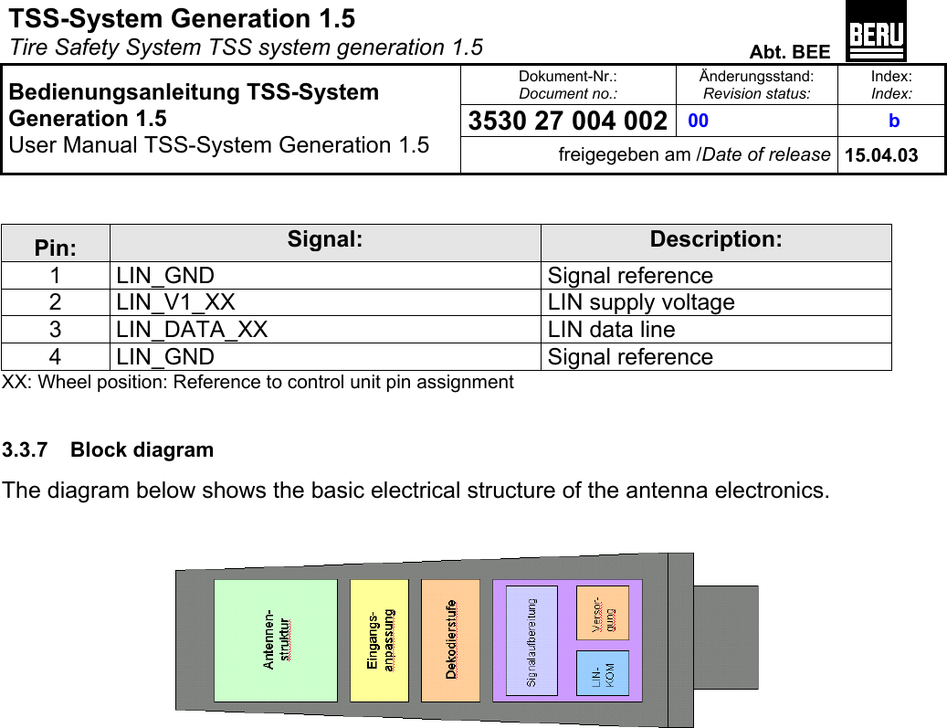
 TSS-DA4 Receiver of a Tire Pressure Monitoring System User Manual Titel

Huf Electronics Bretten GmbH Receiver of a Tire Pressure Monitoring System Titel

Users Manual

TSS-System Generation 1.5   Tire Safety System TSS system generation 1.5  Abt. BEE  Dokument-Nr.: Document no.: Änderungsstand: Revision status: Index: Index: 3530 27 004 002  00   b   Bedienungsanleitung TSS-System Generation 1.5 User Manual TSS-System Generation 1.5 freigegeben am /Date of release 15.04.03      Titel:     Bedienungsanleitung TSS-System Generation 1.5  Title:   User Manual TSS-System Generation 1.5    Dokument Nr.: 3530 27 004 002  00  Document no:    Projekt:   TSS-System Generation 1.5   Project: Tire Safety System TSS system generation 1.5   Revision status: Index: Index: Änd.stand: Revision status Beschreibung: Description Erstellt / Datum: Created / Date: Geprüft / Datum: Checked / Date: Freigegeben /  Datum:  Released / Date: b      00   Revision Saric/ 03.04.03 Kühnle/ 09.04.03 Kessler/ 15.04.03     Revision schedule: Index: Index: Änd.stand: Revision status Beschreibung: Description Erstellt / Datum: Created / Date: Geprüft / Datum: Checked / Date: Freigegeben /  Datum:  Released / Date:                                        a   00   Initial version Kessler/ 20.02.03
TSS-System Generation 1.5   Tire Safety System TSS system generation 1.5  Abt. BEE  Dokument-Nr.: Document no.: Änderungsstand: Revision status: Index: Index: 3530 27 004 002  00   b   Bedienungsanleitung TSS-System Generation 1.5 User Manual TSS-System Generation 1.5 freigegeben am /Date of release 15.04.03   1 SYSTEM AND FUNCTION DESCRIPTION ...................................................................................................... 3 1.1 SYSTEM DESCRIPTION ................................................................................................................................................. 4 2 FUNCTION DESCRIPTION ................................................................................................................................. 6 3 SYSTEM COMPONENTS ..................................................................................................................................... 8 3.1 CONTROL UNIT ........................................................................................................................................................... 8 3.1.1 Temperature range ............................................................................................................................................8 3.1.2 Voltage range.....................................................................................................................................................8 3.1.3 Terminal assignment..........................................................................................................................................9 3.1.4 CAN bus interface ..............................................................................................................................................9 3.1.5 CAN interface data ............................................................................................................................................9 3.2 WHEEL ELECTRONICS ............................................................................................................................................... 10 3.2.1 Fit space...........................................................................................................................................................10 3.2.2 Versions ...........................................................................................................................................................10 3.2.3 Temperature ranges.........................................................................................................................................10 3.2.4 Power supply....................................................................................................................................................10 3.2.5 Pressure measurement .....................................................................................................................................10 3.2.6 Temperature measurement...............................................................................................................................10 3.2.7 Battery monitoring ...........................................................................................................................................10 3.2.8 Transmission rate ............................................................................................................................................10 3.2.9 Block diagram..................................................................................................................................................11 3.3 ANTENNA ................................................................................................................................................................. 12 3.3.1 General dimensions and data ..........................................................................................................................12 3.3.2 433 MHz digital antenna .................................................................................................................................12 3.3.3 315 MHz digital antenna .................................................................................................................................12 3.3.4 Power supply....................................................................................................................................................12 3.3.5 LIN communication with TSS control unit.......................................................................................................12 3.3.6 Terminal assignment, socket connector ...........................................................................................................12 3.3.7 Block diagram..................................................................................................................................................13
TSS-System Generation 1.5   Tire Safety System TSS system generation 1.5  Abt. BEE  Dokument-Nr.: Document no.: Änderungsstand: Revision status: Index: Index: 3530 27 004 002  00   b   Bedienungsanleitung TSS-System Generation 1.5 User Manual TSS-System Generation 1.5 freigegeben am /Date of release 15.04.03   1  System and function description   Section 15.19: Labeling requirements  This device complies with Part15 of the FCC Rules.  Operation is subject to the following two conditions:  (1) this device may not cause harmful interference, and  (2) this device must accept any interference received, including interference that may cause undesired operation.   Section 15.21: Information to the user  The user manual or instruction manual for an intentional or unintentional radiator shall caution  The user that changes or modifications not expressly approved by the party responsible for compliance could void the user’s authority to operate the equipment.
TSS-System Generation 1.5   Tire Safety System TSS system generation 1.5  Abt. BEE  Dokument-Nr.: Document no.: Änderungsstand: Revision status: Index: Index: 3530 27 004 002  00   b   Bedienungsanleitung TSS-System Generation 1.5 User Manual TSS-System Generation 1.5 freigegeben am /Date of release 15.04.03  1.1  System description  The Tire Safety System (TSS) controls and monitors tire pressures. The system comprises the following components: •  1 TSS control unit •  4 TSS wheel electronics units including valve •  4 TSS digital antennas  The basic function of the system is to monitor tire pressure during driving. An electronic unit fitted inside the tire measures the tire pressure and the temperature at regular intervals and transmits the data telemetrically via a HF link to a reception antenna fitted in the wheel housing. In the reception antenna the radio data telegram is decoded and forwarded as a digital signal to the electronic control unit. The control unit evaluates the received data and passes on the information as necessary to the driver, who is then made aware of the need to adjust tire pressures or of a possible puncture situation.  Benefits of the Tire Safety System:  •  Safety An early warning of rapid pressure loss is given. Tire blowouts, resulting from excessive flexing energy caused by driving too fast at low pressures, are avoided. The driver is prompted to adjust the tire pressure as necessary.  •  Convenience Checking of tires is simplified. It is only necessary to remove valve caps and use filling station air dispensers when an adjustment of tire pressure is actually required.  •  Tire innovations Tires with flat-running capabilities mean it is no longer necessary to change a wheel immediately and make the spare wheel superfluous, but they do demand continuous monitoring of tire pressure.  •  Durability and economy: Tire wear is minimized because correct air pressure is maintained.  The system's major additional function is its automatic facility to learn the wheels belonging to the vehicle in question (vehicle wheel identification) and the fitting positions of the vehicle wheels (wheel position detection).  During normal driving this enables the system to match the wheels to the appropriate wheel positions and set the correct pressures without involving the driver.  Optional additional functions cover tire pressure monitoring at standstill:
TSS-System Generation 1.5   Tire Safety System TSS system generation 1.5  Abt. BEE  Dokument-Nr.: Document no.: Änderungsstand: Revision status: Index: Index: 3530 27 004 002  00   b   Bedienungsanleitung TSS-System Generation 1.5 User Manual TSS-System Generation 1.5 freigegeben am /Date of release 15.04.03   •  Flat tire alert before driving off
TSS-System Generation 1.5   Tire Safety System TSS system generation 1.5  Abt. BEE  Dokument-Nr.: Document no.: Änderungsstand: Revision status: Index: Index: 3530 27 004 002  00   b   Bedienungsanleitung TSS-System Generation 1.5 User Manual TSS-System Generation 1.5 freigegeben am /Date of release 15.04.03   2 Function description  The wheel electronics units are fitted inside the tires and measure the tire pressure and the temperature of the wheel electronics. A transmitter in the wheel electronics transmits the measured data from the wheel. For tire pressure monitoring a system with relatively infrequent data transfer is adequate, provided it also has the facility to detect rapid pressure loss. Consequently, the electronics in the wheel can be designed for minimal power consumption and be battery operated.  Each wheel electronics unit has its own ID which is transmitted along with every data transfer. The HF transmission is executed in the 433 MHz range, the so-called ISM band, or in some countries in the 315 MHz range.  Each wheel electronics unit transmits data every 54 seconds. It also measures the tire pressure and the wheel electronics temperature every 3 seconds. In the event of a pressure loss of > 0.2 bar relative to the last pressure value transmitted, the wheel electronics immediately switches to a fast-transmit mode, measuring and transmitting the data every 0.8 seconds.  This means the TSS measures and transmits a considerably greater volume of data than is essential to ensure basic functioning. Consequently, it is able to utilize a data transmission path which does not rely on error-free transfer of each individual data protocol. The data are transferred from the wheel to the vehicle by unidirectional HF transmission. In this mode of HF transmission data telegrams may be subject to disturbance from random external interference sources or from statistical fluctuations in the reception amplitude resulting from varying reception conditions in the wheel housing in respect of wheel rotation and position.  The data transmitted by the wheel electronics are received and decoded by the antennas mounted in the vicinity of the wheel. The decoded data are transmitted via a digital interface (LIN interface) to the control unit.  The control unit evaluates the received data and passes the information as required to the driver information system, so making the driver aware of the need to adjust tire pressures or of a possible puncture situation.  -  A central warning algorithm and wheel management algorithm -  The vehicle-specific onboard power system interface and manufacturer-specific operator control and display philosophy  The system's major additional function is its automatic facility to learn the wheels belonging to the vehicle in question (vehicle wheel identification) and the fitting positions of the vehicle wheels (wheel position detection).
TSS-System Generation 1.5   Tire Safety System TSS system generation 1.5  Abt. BEE  Dokument-Nr.: Document no.: Änderungsstand: Revision status: Index: Index:  00  3530 27 004 002  b   Bedienungsanleitung TSS-System Generation 1.5 User Manual TSS-System Generation 1.5 freigegeben am /Date of release 15.04.03  During normal driving this enables the system to match the wheels to the appropriate wheel positions and set the correct pressures without involving the driver.  Optional additional functions cover tire pressure monitoring at standstill:  •  Flat tire alert before driving off    A  4A  3 A  2 Antenna 1 TSS control unit HF receiver Function software TSS-LIN interface Function software TSS-LINinterfaceCAN interface CAN bus  To driver information systemTSS-LIN-Bus             RE 2  RE 3  RE 4 Wheel elec.        1  Figure 1 - Block diagram, TSS system generation 1.5
TSS-System Generation 1.5   Tire Safety System TSS system generation 1.5  Abt. BEE  Dokument-Nr.: Document no.: Änderungsstand: Revision status: Index: Index: 3530 27 004 002  00   b   Bedienungsanleitung TSS-System Generation 1.5 User Manual TSS-System Generation 1.5 freigegeben am /Date of release 15.04.03    3 System components  The components of the TSS are presented in the following.   3.1 Control unit  The electronic control unit comprises a circuit board with a microprocessor control, a CAN bus interface and a TSS-LIN bus interface.  The control unit captures and evaluates the tire information received from the digital antennas. The pressure data, and warnings as and when required, are transmitted over the CAN bus to the vehicle's display systems. The data from the digital antennas are transmitted via a LIN communication link to the control unit. The control unit is the LIN master, while the antennas operate as slaves. The following sections set out the key data of the control unit.  3.1.1 Temperature range Operating temperature:       -40°C ... +80°C Storage temperature:      -40°C ... 120°C 3.1.2 Voltage range Terminal 30, rated voltage:    12V Terminal 30, operating voltage:    9V ... 16V Terminal 30, maximum voltage:    0... +27V, with inverse-polarity protection Voltage overload shutdown:    Control unit shutdown at UB > 27V Low voltage shutdown:      Control unit shutdown at UB < 6V Number of suppliable digital antennas:  5
TSS-System Generation 1.5   Tire Safety System TSS system generation 1.5  Abt. BEE  Dokument-Nr.: Document no.: Änderungsstand: Revision status: Index: Index: 3530 27 004 002  00   b   Bedienungsanleitung TSS-System Generation 1.5 User Manual TSS-System Generation 1.5 freigegeben am /Date of release 15.04.03   3.1.3 Terminal assignment Design:          Pin trough with 90° angled solderable pins Number of contact pins:      32 pins  1   Terminal 31 Gnd   17     --------------------------------- 2   Terminal 30 Battery positive 12V   18     --------------------------------- 3       ----------------------------------  19     --------------------------------- 4       ----------------------------------  20     --------------------------------- 5   LIN GND RR   21     --------------------------------- 6   LIN_DATA_RR   22     LIN_V1_RR 7       LIN_DATA_HR  23     LIN_V1_HR 8   ----------------------------------  24     LIN_GND_HL 9   LIN_DATA_HL  25     LIN_V1_HL 10     LIN_DATA_VR  26     LIN_V1_VR 11   LIN_GND_VL  27     LIN_GND_VL 12   LIN_DATA_VL  28     LIN_V1_VL 13     ----------------------------------  29     --------------------------------- 14     ----------------------------------  30     --------------------------------- 15   CAN bus 1, high  31   CAN bus 2, low   16     CAN bus Gnd  (= terminal 31)  32     ---------------------------------  3.1.4  CAN bus interface Bus:    Convenience CAN system CAN specification:    CAN Low Speed Class B ISO DIS 11519 Communication partners:  All systems on the convenience CAN,         particularly instrument cluster and CAN/CAN gateway 3.1.5  CAN interface data Driver block:   TJA1054 Can H / Can L wire:   Short-proof against GND and +UB CAN bit rate:     100 kBaud +/-5%
TSS-System Generation 1.5   Tire Safety System TSS system generation 1.5  Abt. BEE  Dokument-Nr.: Document no.: Änderungsstand: Revision status: Index: Index:  00  3530 27 004 002  b   Bedienungsanleitung TSS-System Generation 1.5 User Manual TSS-System Generation 1.5 freigegeben am /Date of release 15.04.03    3.2 Wheel electronics  The wheel electronics unit registers the tire pressure and the air temperature in the tire and transmits it over a predefined radio link together with the remaining battery life and the ID to the adjacent digital antenna. 3.2.1 Fit space The wheel electronics unit is fitted together with a valve on the wheel rim, and sits in the well base. The BERU fitting instructions must be followed.  3.2.2 Versions Because of the differing country-specific approval conditions for radio-assisted electronic systems, based on local circumstances such as operation of military radio communications, private mobile radio systems etc., different variants of the wheel electronics units transmitting on different carrier frequencies are required.  -   433 MHz wheel electronics unit -  315 MHz wheel electronics unit 3.2.3 Temperature ranges Operating temperature:    -40°C ... +120°C 3.2.4 Power supply Battery life, averaged:   7 years 3.2.5 Pressure measurement Measuring range:      0 to 6.375 bar, absolute 3.2.6 Temperature measurement Measuring range:      - 40°C to + 120°C 3.2.7 Battery monitoring At the end of each transmission the remaining battery life is measured. 3.2.8 Transmission rate       9.6 k bps +/- 10%
TSS-System Generation 1.5   Tire Safety System TSS system generation 1.5  Abt. BEE  Dokument-Nr.: Document no.: Änderungsstand: Revision status: Index: Index:  00  3530 27 004 002  b   Bedienungsanleitung TSS-System Generation 1.5 User Manual TSS-System Generation 1.5 freigegeben am /Date of release 15.04.03  3.2.9 Block diagram The adjacent diagram shows the basic electrical structure of the wheel electronics.          For measurement of the absolute pressure a relatively low frequency of measurement data transmissions is sufficient, but a pressure loss must be transmitted immediately. The wheel electronics unit adjusts automatically to the various operating modes in order to carry out these functions at minimum power consumption.  Transmitting intervals 1.  Normally each wheel electronics unit measures the tire pressure and the approximate temperature of the air in the tire every three seconds, but if the measured values are stable transmissions are executed only every 54 seconds.  2.  At a pressure loss of more than 0.2 bar per minute, the wheel electronics unit switches temporarily to an alarm mode at a high transmission frequency. It then measures and transmits data every 0.8 seconds. This power management system permits battery-powered operation with adequate durability.       Safety instructions for battery:  Dispose of used batteries in accordance with local legislation.
TSS-System Generation 1.5   Tire Safety System TSS system generation 1.5  Abt. BEE  Dokument-Nr.: Document no.: Änderungsstand: Revision status: Index: Index: 3530 27 004 002  00   b   Bedienungsanleitung TSS-System Generation 1.5 User Manual TSS-System Generation 1.5 freigegeben am /Date of release 15.04.03    3.3 Antenna  The digital antenna has a built-in signal processor (decoding processor) to receive and decode the HF signals transmitted by the wheel electronics. The processed information is transmitted via a LIN communication link to the TSS control unit. 3.3.1  General dimensions and data Receiver bandwidth:      550kHz @ -85dBm / 20°C Modulation type:    FSK, hard keyed Radio data rate:        9.6 kBaud +/- 10% 3.3.2  433 MHz digital antenna Radio reception frequency:    433.92 MHz +250kHz / - 250 kHz 3.3.3  315 MHz digital antenna Radio reception frequency:    315.00 MHz +250kHz / - 250 kHz 3.3.4 Power supply Supply cable:  Two-wire cable, Ubatt , Gnd  for each digital antenna Supply voltage:  > (Ubatt – 2V) 3.3.5  LIN communication with TSS control unit The LIN communication of the antennas with the TSS control unit conforms to the LIN Consortium specification, version 1.1. The TSS control unit operates in master mode and the antennas in slave mode. Key data: LIN bit rate:     10 kBaud +/-2% LIN driver:     Philips TJA 1020  3.3.6  Terminal assignment, socket connector Design:     Pin trough  Number of contact pins:      4 pins Pin design:     Sealed, gold-plated Pitch:      2.54 x 2.54 mm
TSS-System Generation 1.5   Tire Safety System TSS system generation 1.5  Abt. BEE  Dokument-Nr.: Document no.: Änderungsstand: Revision status: Index: Index:  00  3530 27 004 002  b   Bedienungsanleitung TSS-System Generation 1.5 User Manual TSS-System Generation 1.5 freigegeben am /Date of release 15.04.03   Pin:  Signal:  Description: 1 LIN_GND  Signal reference 2  LIN_V1_XX  LIN supply voltage 3  LIN_DATA_XX  LIN data line 4  LIN_GND   Signal reference XX: Wheel position: Reference to control unit pin assignment  3.3.7 Block diagram The diagram below shows the basic electrical structure of the antenna electronics.

Navigation menu