Hunt Electronic HLC8JMD Wireless IP CAMERA User Manual
Hunt Electronic Co., Ltd. Wireless IP CAMERA Users Manual
UserManual.wiki
>
Hunt Electronic
>
HLC8JMD User Manual
Users Manual
Navigation menu
Upload a User Manual
Namespaces
Wiki Guide
HTML
PDF
Info
Views
User Manual
Discussion / Help
Navigation
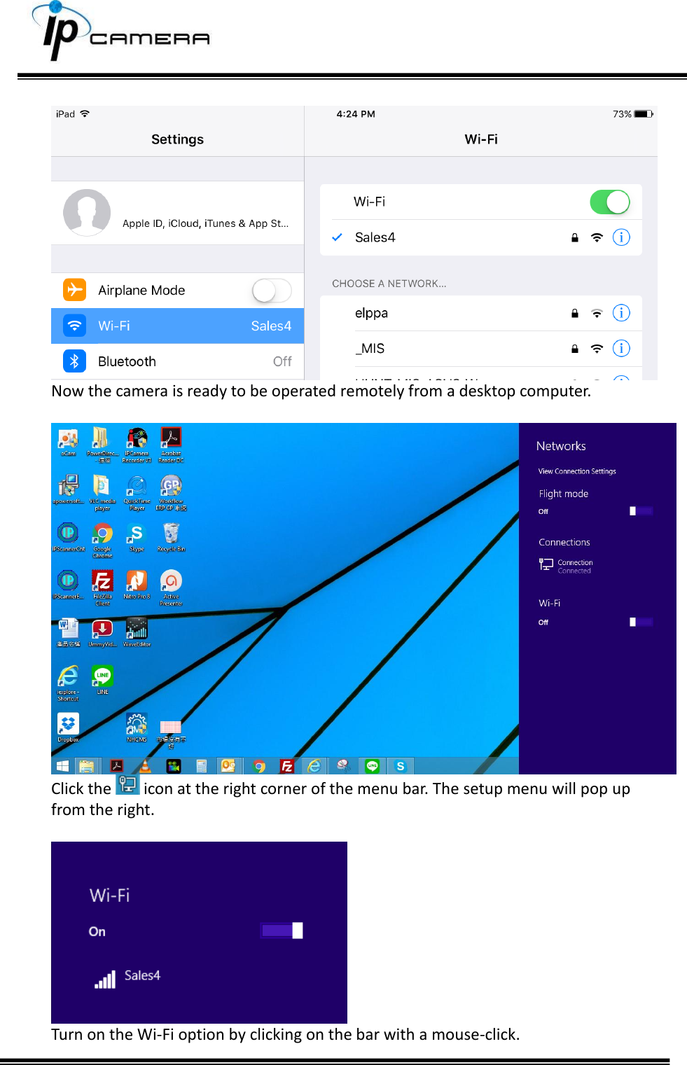
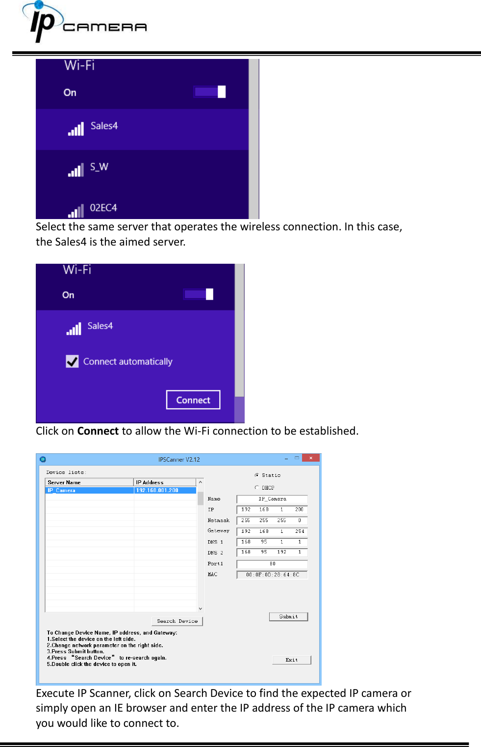
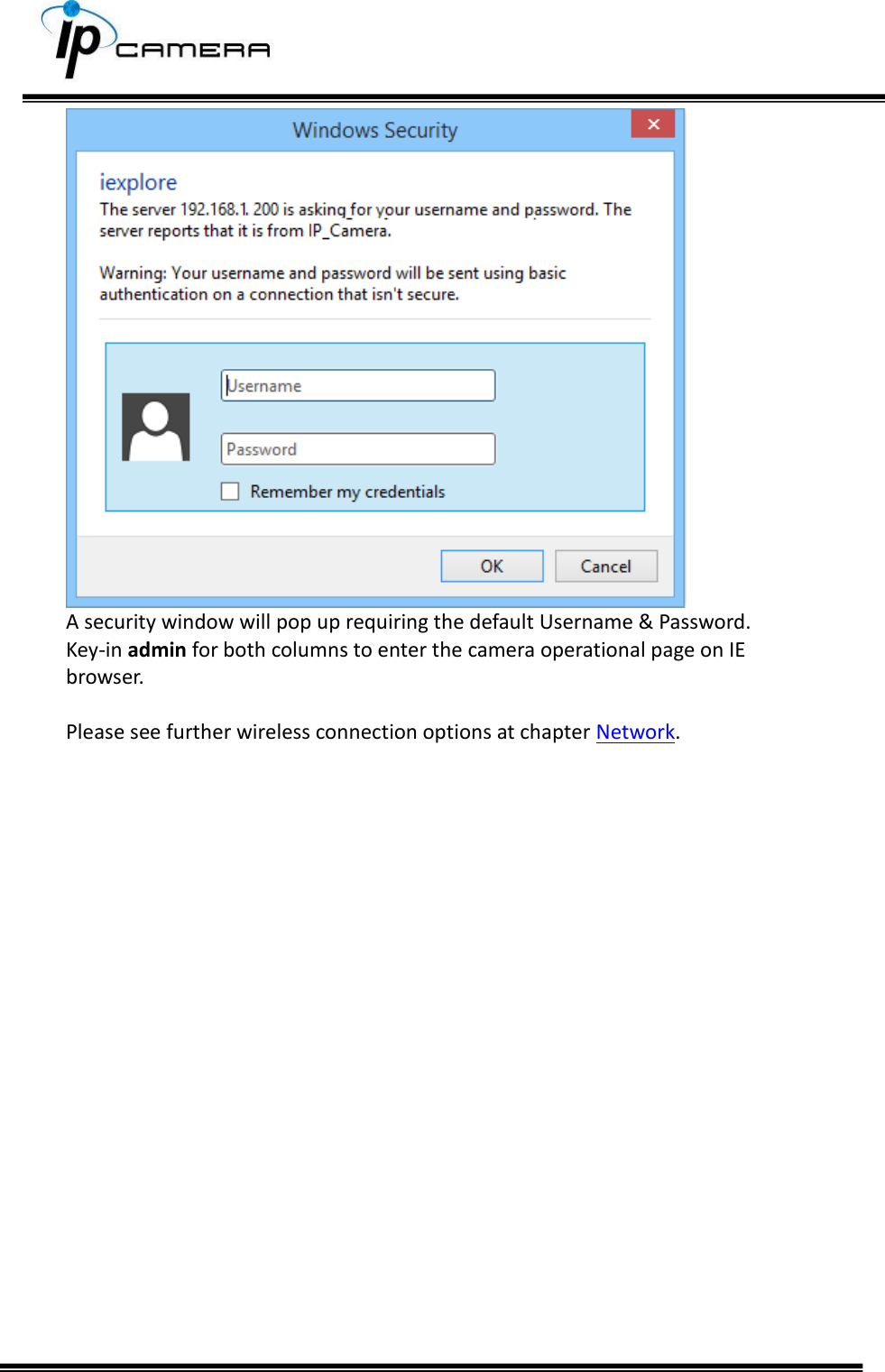
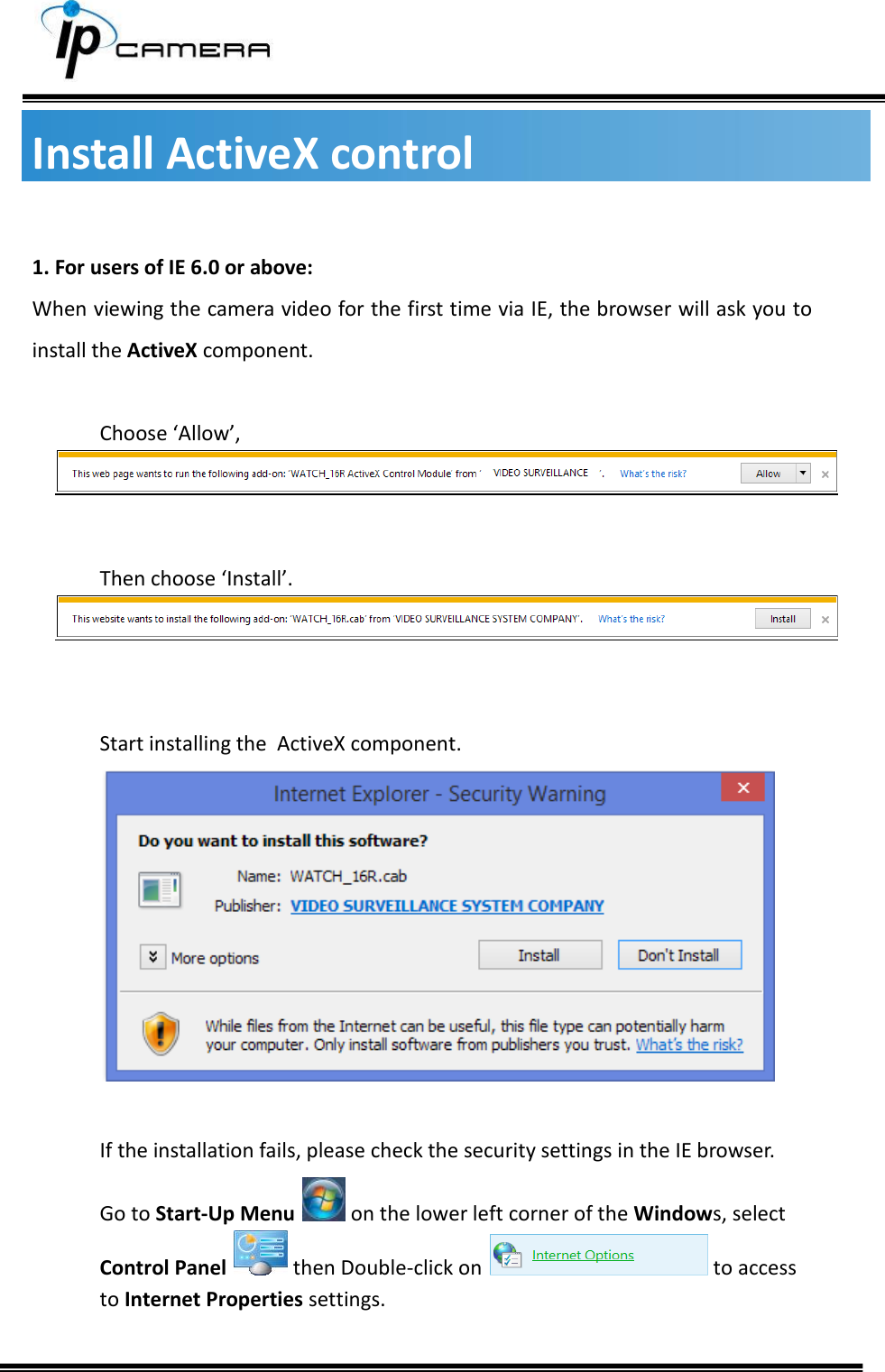
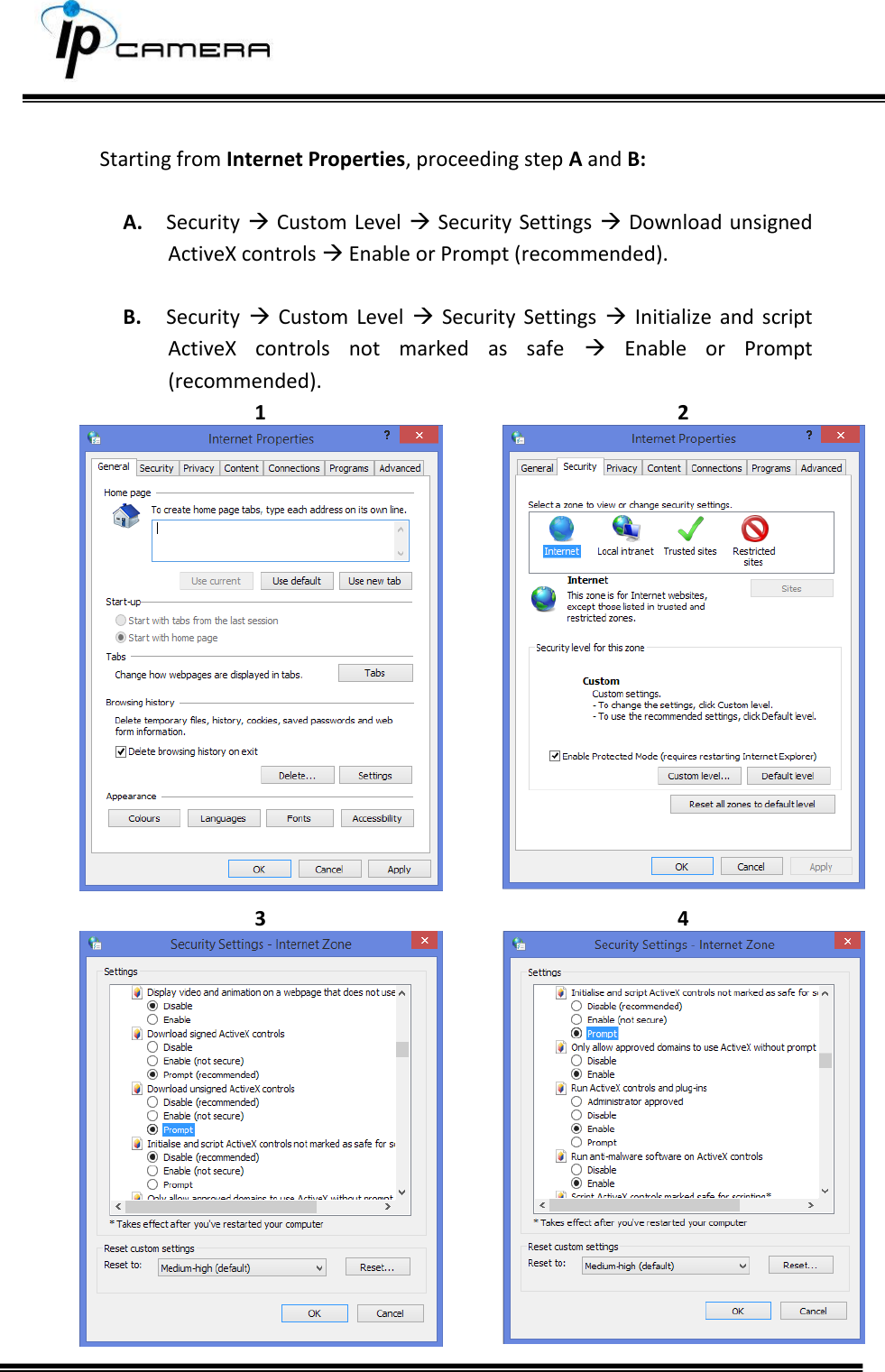
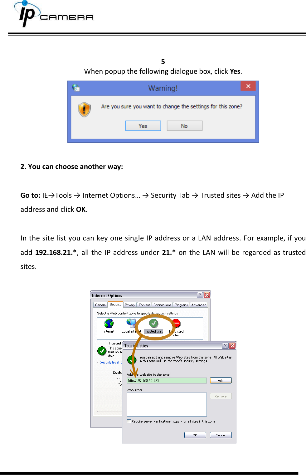
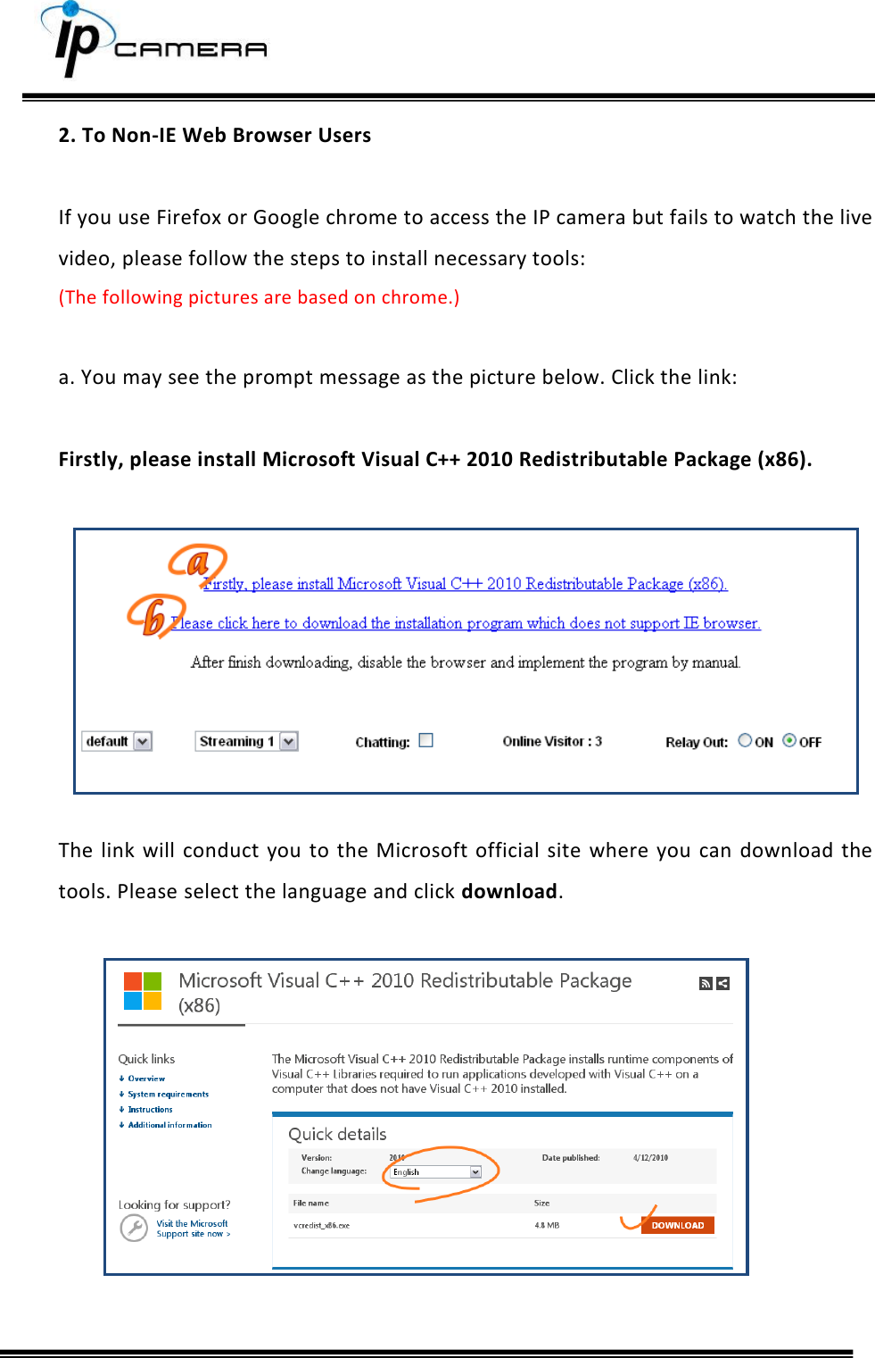
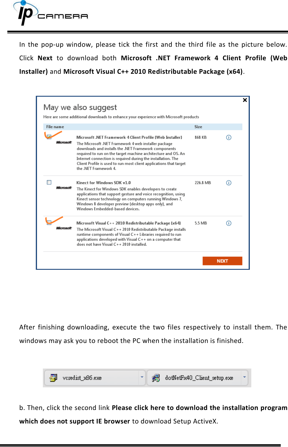

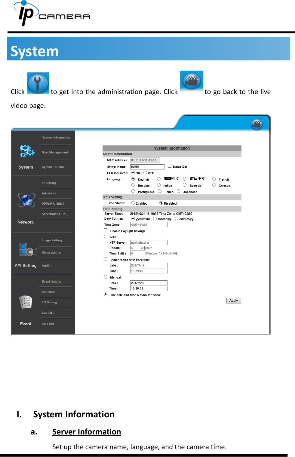
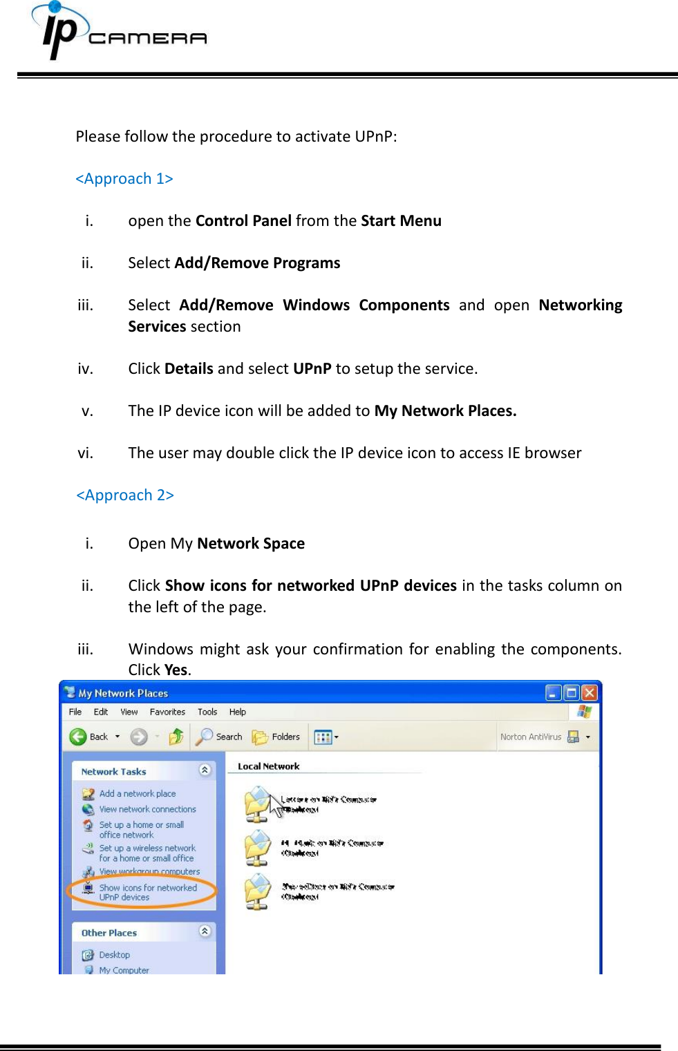
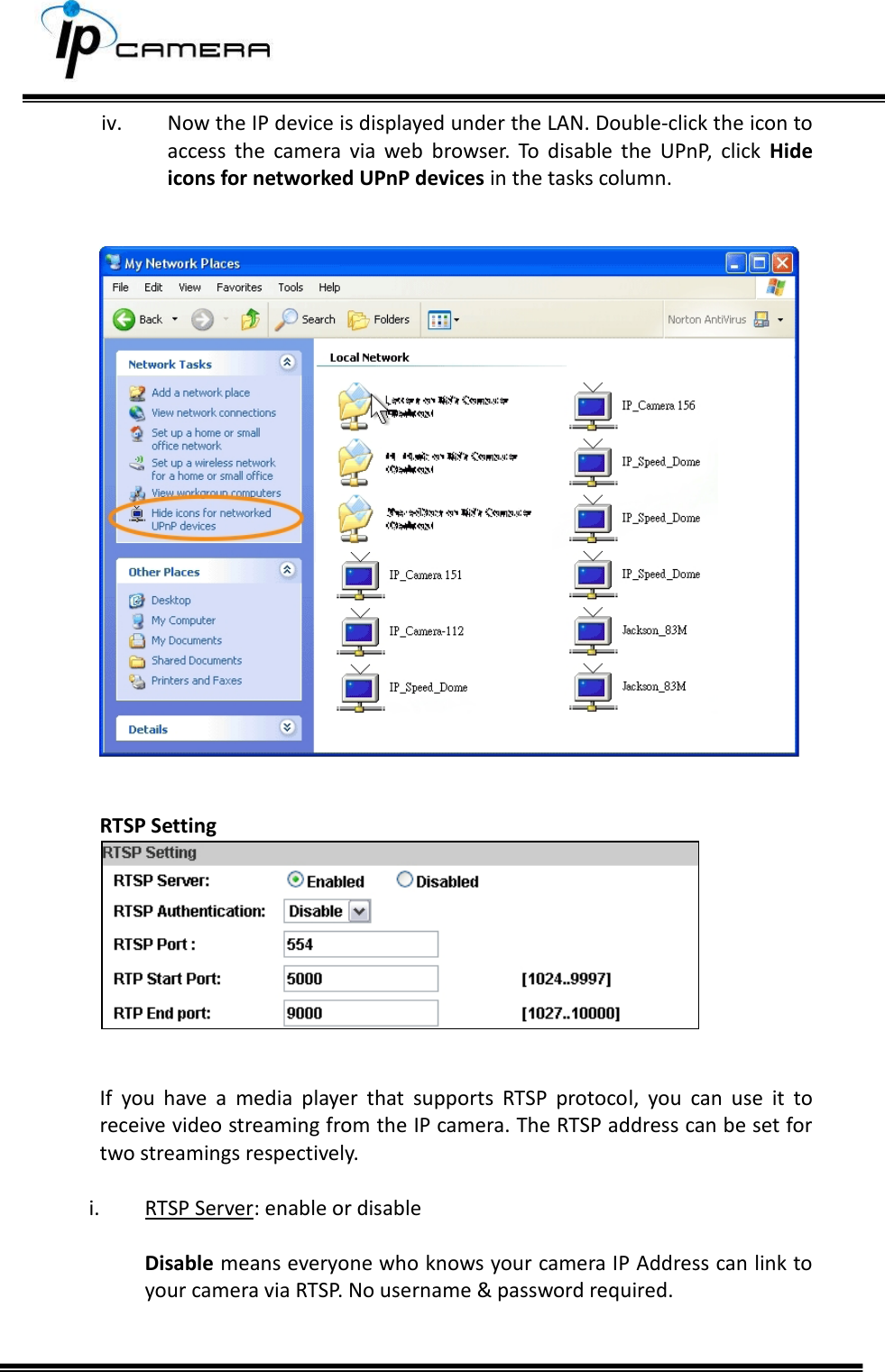
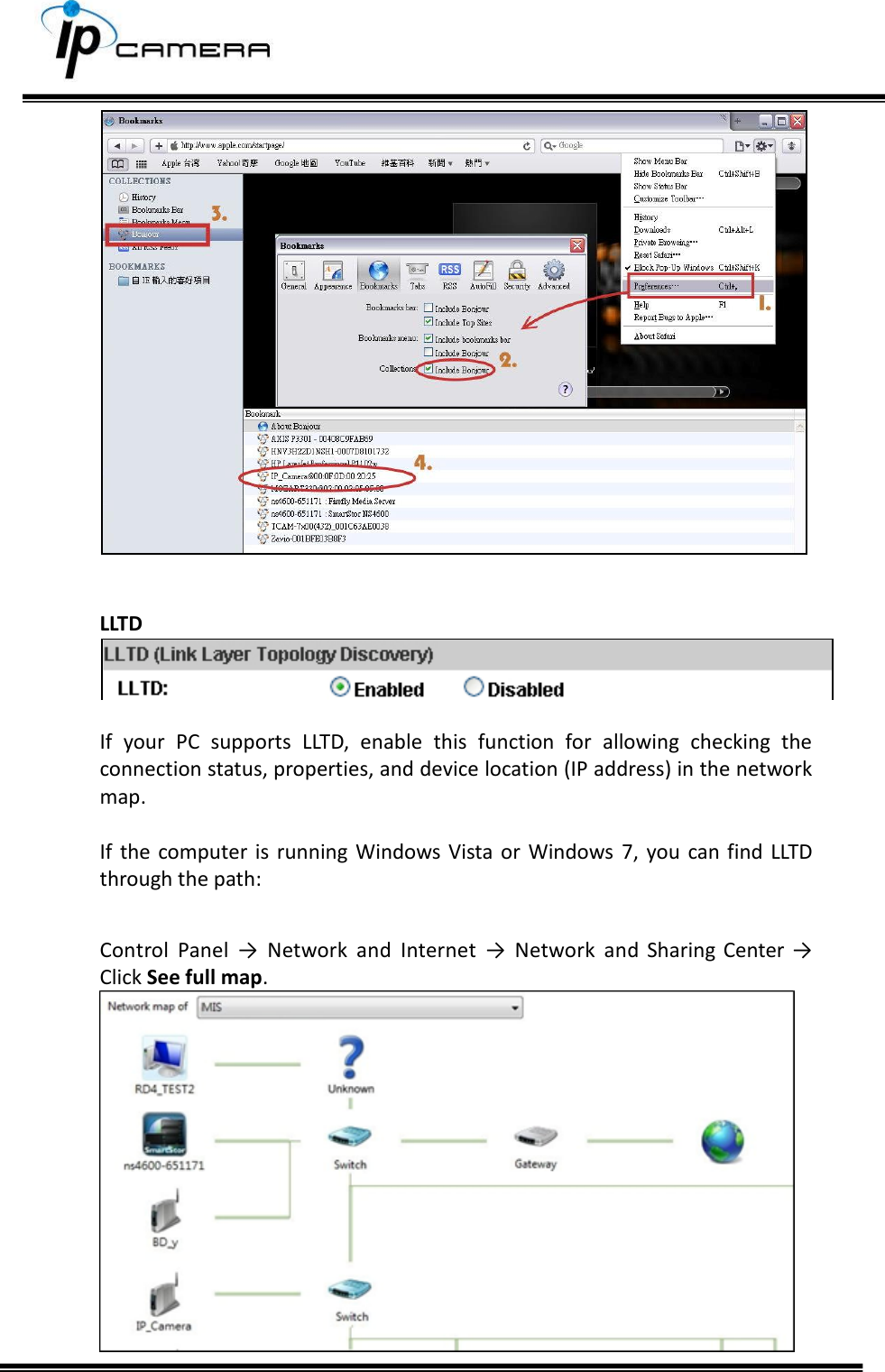
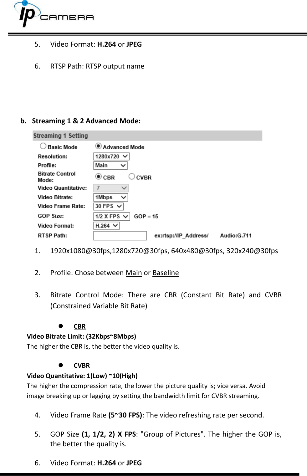
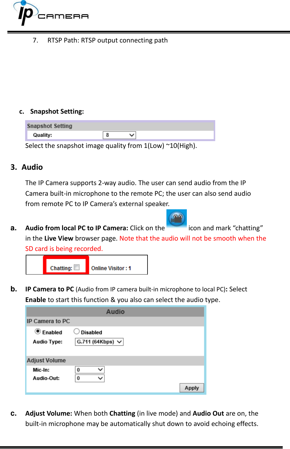
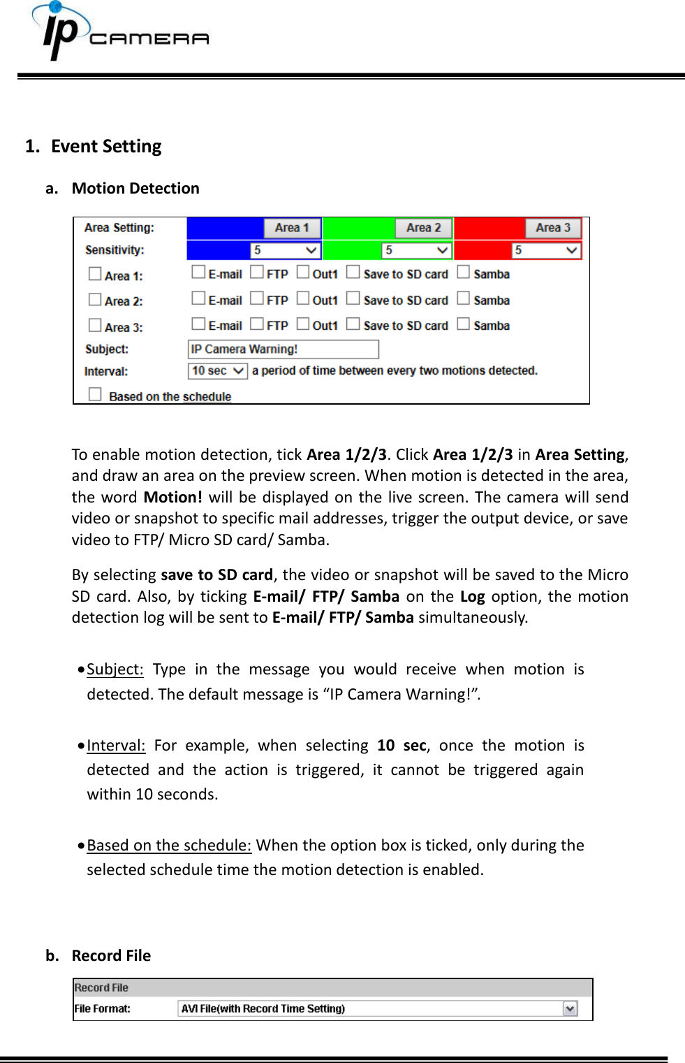
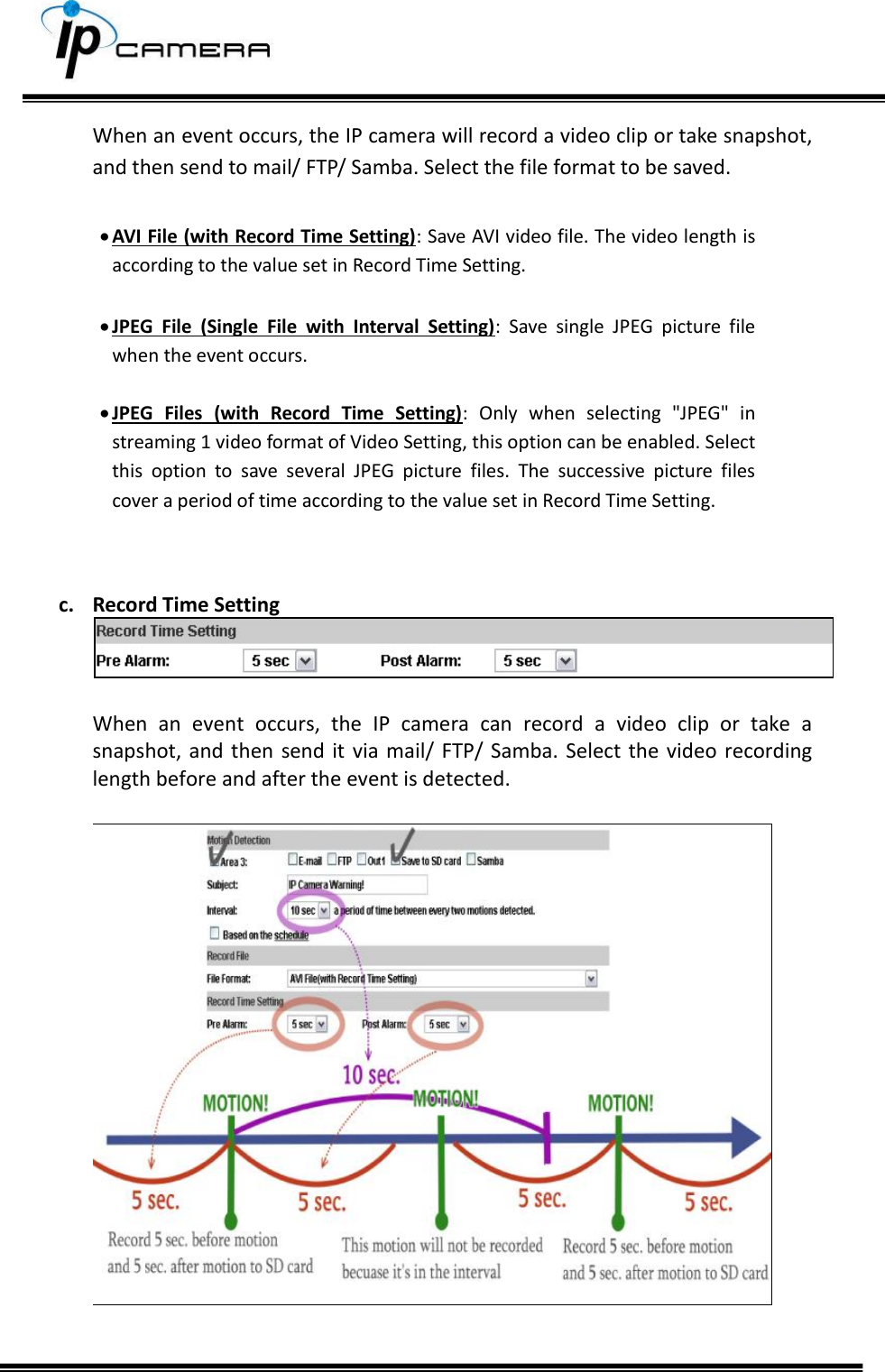
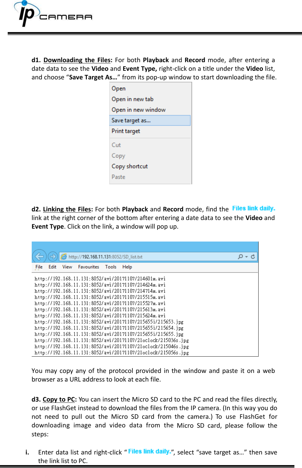
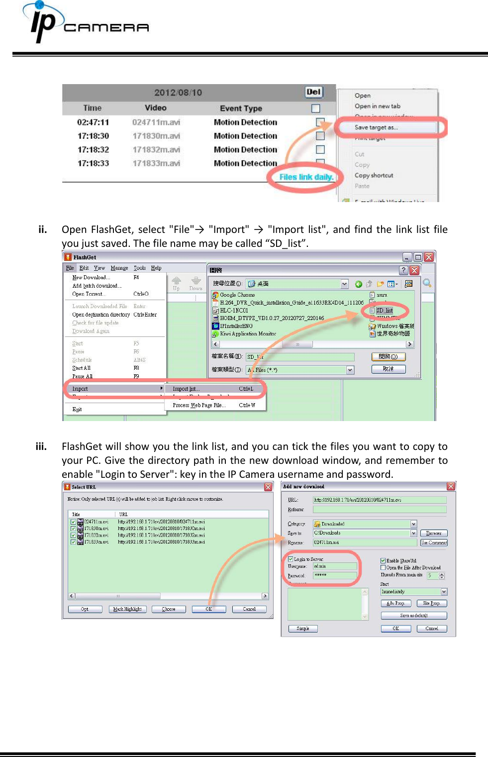
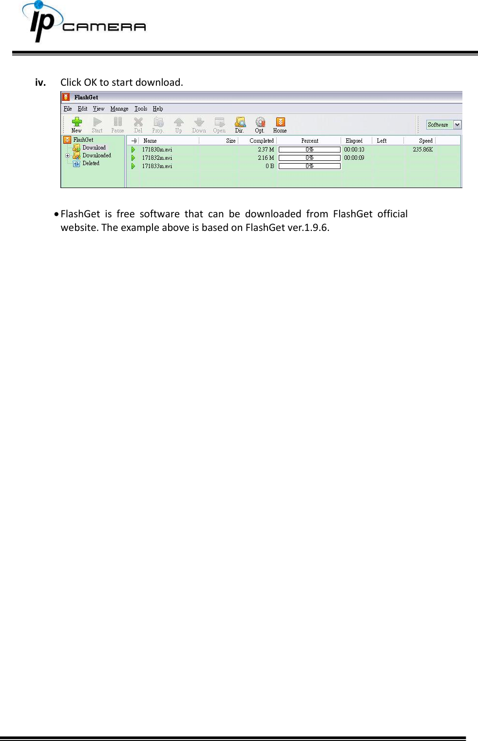
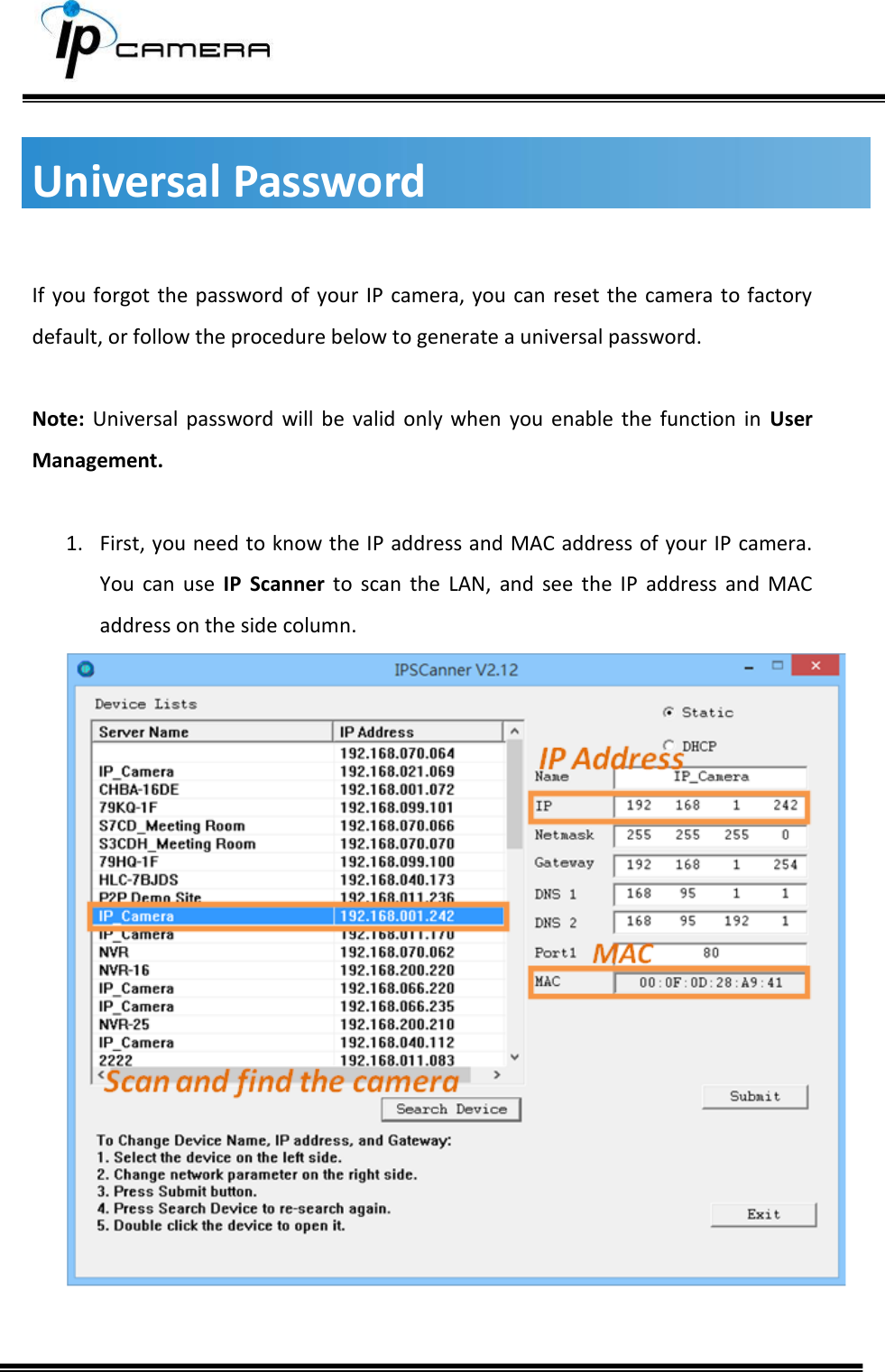
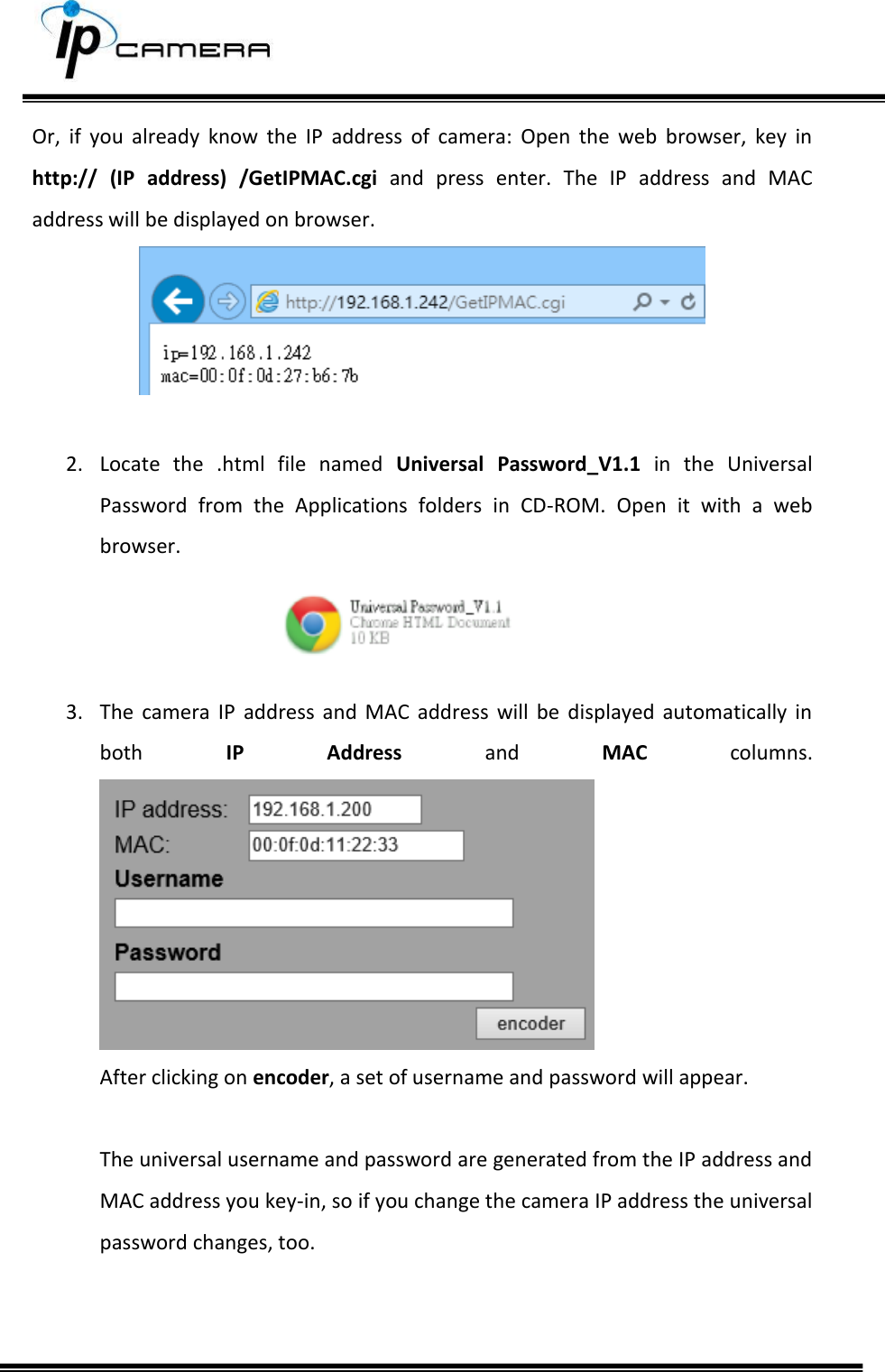
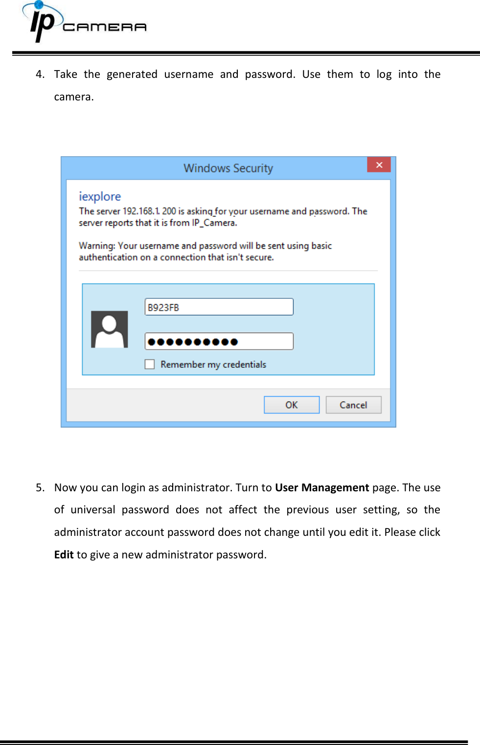
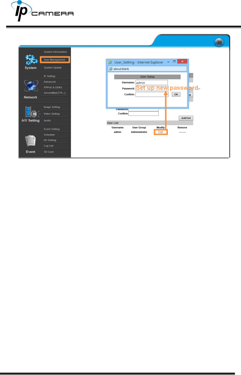
![ Automatically generated IPv6 Address: Indicates a virtual IPv6 address generated automatically by the IP camera. This virtual IPv6 address cannot be used on WAN. To use IPv6 address to access the IP camera, open the web browser, and key-in the [IPv6 address] in the address bar. The [ ] parentheses mark is necessary. a. Port Assignment: The user might need to assign a different port to avoid conflicts when setting up the IP. b. Web Page Port: setup the web page connecting port and video transmitting port (Default: 80) c. HTTPs Port: setup the https port(Default: 443) UPnP This IP camera supports UPnP, if this service is enabled on your computer, the camera will automatically be detected and a new icon will be added to My Network Places. UPnP Port Forwarding:Enable UPnP Port Forwarding for accessing the IP Camera from the Internet; this option allows the IP Camera to open ports on the router automatically so that video streams can be sent out from a LAN. There are three external ports for being set: Web Port, Http Port and RTSP port. To utilize of this feature, make sure that your router supports UPnP and is activated. Note: UPnP must be enabled on your computer.](https://usermanual.wiki/Hunt-Electronic/HLC8JMD/User-Guide-3804620-Page-35.png)